Configuring IP Storage
Cisco MDS 9000 Family IP storage (IPS) services extend the reach of Fibre Channel SANs by using open-standard, IP-based technology. The switch connects separated SAN islands using Fibre Channel over IP (FCIP), and it allows IP hosts to access Fibre Channel storage using the iSCSI protocol.
 Note |
FCIP and iSCSI features are specific to the IPS module and are available in Cisco MDS 9200 Switches or Cisco MDS 9500 Directors.The Cisco MDS 9216I switch and the 14/2 Multiprotocol Services (MPS-14/2) module also allow you to use Fibre Channel, FCIP, and iSCSI features. The MPS-14/2 module is available for use in any switch in the Cisco MDS 9200 Series or Cisco MDS 9500 Series. |
This chapter includes the following topics:
Information About IP Storage
The IP Storage services module (IPS module) and the MPS-14/2 module allow you to use FCIP and iSCSI features. FCIP and iSCSI features are specific to the IPS module and are available in Cisco MDS 9200 Switches or Cisco MDS 9500 Directors. The switch connects separated SAN islands using Fibre Channel over IP (FCIP), and it allows IP hosts to access Fibre Channel storage using the iSCSI protocol.
-
FCIP—FCIP transports Fibre Channel frames transparently over an IP network between two Cisco MDS 9000 Family switches or other FCIP standards-compliant devices.
-
iSCSI—The IPS module provides IP hosts access to Fibre Channel storage devices. The IP host sends SCSI commands encapsulated in iSCSI protocol data units (PDUs) to a Cisco MDS 9000 Family switch IPS port over a TCP/IP connection. At this point, the commands are routed from an IP network into a Fibre Channel network and forwarded to the intended target.
The IP Storage services module (IPS module) and the MPS-14/2 module allow you to use FCIP and iSCSI features. Both modules integrate seamlessly into the Cisco MDS 9000 Family, and support the full range of features available on other switching modules, including VSANs, security, and traffic management. The following types of storage services modules are currently available for use in any switch in the Cisco MDS 9200 Series or in the Cisco MDS 9500 Series:
-
The 4-port, hot-swappable IPS module (IPS-4) has four Gigabit Ethernet ports.
-
The 8-port, hot-swappable IPS module (IPS-8) has eight Gigabit Ethernet ports.
-
The MPS-14/2 module has 14 Fibre Channel ports (numbered 1 through 14) and two Gigabit Ethernet ports (numbered 1 and 2).
Gigabit Ethernet ports in these modules can be configured to support the FCIP protocol, the iSCSI protocol, or both protocols simultaneously:
-
FCIP—FCIP transports Fibre Channel frames transparently over an IP network between two Cisco MDS 9000 Family switches or other FCIP standards-compliant devices.
Figure 1 shows how the IPS module is used in different FCIP scenarios.
-
iSCSI—The IPS module provides IP hosts access to Fibre Channel storage devices. The IP host sends SCSI commands encapsulated in iSCSI protocol data units (PDUs) to a Cisco MDS 9000 Family switch IPS port over a TCP/IP connection. At this point, the commands are routed from an IP network into a Fibre Channel network and forwarded to the intended target.
Figure 2 depicts the iSCSI scenarios in which the IPS module is used.
This section contains the following topics:
IPS Module Upgrade
 Caution |
A software upgrade is only disruptive for the IPS module. The NX-OS software continues to support nondisruptive software upgrades for Fibre Channel modules in the switch and for the switch itself. |
IPS modules use a rolling upgrade install mechanism where each module in a given switch can only be upgraded in sequence. To guarantee a stable state, each IPS module in a switch requires a 5-minute delay before the next IPS module is upgraded.
MPS-14/2 Module Upgrade
Caution |
A software upgrade is only partially disruptive for the MPS-14/2 module. The NX-OS software continues to support nondisruptive software upgrades for Fibre Channel modules in the switch and for the switch itself. |
The MPS-14/2 modules have 14 Fibre Channel ports (nondisruptive upgrade) and two Gigabit Ethernet ports (disruptive upgrade). MPS-14/2 modules use a rolling upgrade install mechanism for the two Gigabit Ethernet ports where each module in a given switch can only be upgraded in sequence. To guarantee a stable state, each MPS-14/2 module in a switch requires a 5-minute delay before the next module is upgraded.
Supported Hardware
You can configure the FCIP and iSCSI features using one or more of the following hardware:
- IPS-4 and IPS-8 modules (refer to the Cisco MDS 9200 Series Hardware Installation Guide or the Cisco MDS 9500 Series Hardware Installation Guide for more information)
- MPS-14/2 module (refer to the Cisco MDS 9200 Series Hardware Installation Guide or the Cisco MDS 9500 Series Hardware Installation Guide for more information).
Note |
In both the MPS-14/2 module and the Cisco MDS 9216i integrated supervisor module, the port numbering differs for the Fibre Channel ports and the Gigabit Ethernet ports. The Fibre Channel ports are numbered from 1 through 14 and the Gigabit Ethernet ports are numbered 1 and 2. |
- Cisco MDS 9216i Switch (refer to the Cisco MDS 9200 Series Hardware Installation Guide ).
Gigabit Ethernet Interfaces for IPv4 Configuration
Both FCIP and iSCSI rely on TCP/IP for network connectivity. On each IPS module or MPS-14/2 module, connectivity is provided in the form of Gigabit Ethernet interfaces that are appropriately configured.
A new port mode, called IPS, is defined for Gigabit Ethernet ports on each IPS module or MPS-14/2 module. IP storage ports are implicitly set to IPS mode, so it can be used to perform only iSCSI and FCIP storage functions. IP storage ports do not bridge Ethernet frames or route other IP packets.
Each IPS port represents a single virtual Fibre Channel host in the Fibre Channel SAN. All iSCSI hosts connected to this IPS port are merged and multiplexed through the single Fibre Channel host.
Note |
For information about configuring FCIP, see the Configuring FCIP chapter. For information about configuring iSCSI, see the Configuring iSCSI chapter. |
In large scale iSCSI deployments where the Fibre Channel storage subsystems require explicit LUN access control for every host device, use of proxy-initiator mode simplifies the configuration.
Note |
The Gigabit Ethernet interfaces on the MPS-14/2 module do not support EtherChannel. |
Note |
To configure IPv6 on a Gigabit Ethernet interface, see the Security Configuration Guide, Cisco DCNM for SAN. |
 Tip |
Gigabit Ethernet ports on any IPS module or MPS-14/2 module should not be configured in the same Ethernet broadcast domain as the management Ethernet port—they should be configured in a different broadcast domain, either by using separate standalone hubs or switches or by using separate VLANs. |
Basic Gigabit Ethernet Configuration
The following figure shows an example of a basic Gigabit Ethernet IP version 4 (IPv4) configuration.
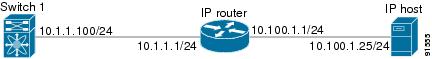
The port on the Ethernet switch to which the Gigabit Ethernet interface is connected should be configured as a host port (also known as access port) instead of a switch port. Spanning tree configuration for that port (on the Ethernet switch) should disabled. This helps avoid the delay in the management port coming up due to delay from Ethernet spanning tree processing that the Ethernet switch would run if enabled. For Cisco Ethernet switches, use either the switchport host command in Cisco IOS or the set port host command in Catalyst OS.
IPS Module Core Dumps
IPS core dumps are different from the system’s kernel core dumps for other modules. When the IPS module’s operating system (OS) unexpectedly resets, it is useful to obtain a copy of the memory image (called a IPS core dump) to identify the cause of the reset. Under that condition, the IPS module sends the core dump to the supervisor module for storage. Cisco MDS switches have two levels of IPS core dumps:
- Partial core dumps (default)—Each partial core dump consists of four parts (four files). All four files are saved in the active supervisor module.
Use the show cores command to list these files.
- Full core dumps—Each full core dump consists of 75 parts (75 files). The IPS core dumps for the MPS-14/2 module and the Cisco MDS 9216i Switch only contains 38 parts. This dump cannot be saved on the supervisor module because of its large space requirement. They are copied directly to an external TFTP server.
Use the system cores tftp: command to configure an external TFTP server to copy the IPS core dump (and other core dumps).
Interface Descriptions Configuration
See the Interfaces Configuration Guide, Cisco DCNM for SAN for details on configuring the switch port description for any interface.
Beacon Mode Configuration
See the Interfaces Configuration Guide, Cisco DCNM for SAN for details on configuring the beacon mode for any interface.
Autonegotiation Configuration
By default, autonegotiation is enabled all Gigabit Ethernet interface. You can enable or disable autonegotiation for a specified Gigabit Ethernet interface. When autonegotiation is enabled, the port automatically detects the speed or pause method, and duplex of incoming signals based on the link partner. You can also detect link up conditions using the autonegotiation feature.
MTU Frame Size Configuration
You can configure the interfaces on a switch to transfer large (or jumbo) frames on a port. The default IP maximum transmission unit (MTU) frame size is 1500 bytes for all Ethernet ports. By configuring jumbo frames on a port, the MTU size can be increased up to 9000 bytes.
Note |
The minimum MTU size is 576 bytes. |
Tip |
MTU changes are disruptive, all FCIP links and iSCSI sessions flap when the software detects a change in the MTU size. |
Promiscuous Mode Configuration
You can enable or disable promiscuous mode on a specific Gigabit Ethernet interface. By enabling the promiscuous mode, the Gigabit Ethernet interface receives all the packets and the software then filters and discards the packets that are not destined for that Gigabit Ethernet interface.
About VLANs for Gigabit Ethernet
Virtual LANs (VLANs) create multiple virtual Layer 2 networks over a physical LAN network. VLANs provide traffic isolation, security, and broadcast control.
Gigabit Ethernet ports automatically recognize Ethernet frames with IEEE 802.1Q VLAN encapsulation. If you need to have traffic from multiple VLANs terminated on one Gigabit Ethernet port, configure subinterfaces—one for each VLAN.
If the IPS module or MPS-14/2 module is connected to a Cisco Ethernet switch, and you need to have traffic from multiple VLANs coming to one IPS port, verify the following requirements on the Ethernet switch:
- The Ethernet switch port connected to the IPS module or MPS-14/2 module is configured as a trunking port.
- The encapsulation is set to 802.1Q and not ISL, which is the default.
Use the VLAN ID as a subscription to the Gigabit Ethernet interface name to create the subinterface name: slot-number / port-numberVLAN-ID .
Interface Subnet Requirements
Gigabit Ethernet interfaces (major), subinterfaces (VLAN ID), and management interfaces (mgmt 0) can be configured in the same or different subnet depending on the configuration (see Table 1).
|
Interface 1 |
Interface 2 |
Same Subnet Allowed |
Notes |
|---|---|---|---|
|
Gigabit Ethernet 1/1 |
Gigabit Ethernet 1/2 |
Yes |
Two major interfaces can be configured in the same or different subnets. |
|
Gigabit Ethernet 1/1.100 |
Gigabit Ethernet 1/2.100 |
Yes |
Two subinterfaces with the same VLAN ID can be configured in the same or different subnets. |
|
Gigabit Ethernet 1/1.100 |
Gigabit Ethernet 1/2.200 |
No |
Two subinterfaces with different VLAN IDs cannot be configured in the same subnet. |
|
Gigabit Ethernet 1/1 |
Gigabit Ethernet 1/1.100 |
No |
A subinterface cannot be configured on the same subnet as the major interface. |
|
mgmt0 |
Gigabit Ethernet 1/1.100 |
No |
The mgmt0 interface cannot be configured in the same subnet as the Gigabit Ethernet interfaces or subinterfaces. |
|
mgmt0 |
Gigabit Ethernet 1/1 |
No |
Note |
The configuration requirements in Table 1 also apply to Ethernet PortChannels. |
Verifying Gigabit Ethernet Connectivity
Once the Gigabit Ethernet interfaces are connected with valid IP addresses, verify the interface connectivity on each switch. Ping the IP host using the IP address of the host to verify that the static IP route is configured correctly.
Note |
If the connection fails, verify the following, and ping the IP host again:- The IP address for the destination (IP host) is correctly configured.- The host is active (powered on). - The IP route is configured correctly. - The IP host has a route to get to the Gigabit Ethernet interface subnet. - The Gigabit Ethernet interface is in the up state. |
Gigabit Ethernet High Availability
Virtual Router Redundancy Protocol (VRRP) and Ethernet PortChannels are two Gigabit Ethernet features that provide high availability for iSCSI and FCIP services.
VRRP for iSCSI and FCIP Services
VRRP provides a redundant alternate path to the Gigabit Ethernet port for iSCSI and FCIP services. VRRP provides IP address failover protection to an alternate Gigabit Ethernet interface so the IP address is always available (see Figure 1).
All members of the VRRP group (see Figure 1) must be IP storage Gigabit Ethernet ports. VRRP group members can be one or more of the following interfaces:
-
One or more interfaces in the same IPS module or MPS-14/2 module
-
Interfaces across IPS modules or MPS-14/2 modules in one switch
-
Interfaces across IPS modules or MPS-14/2 modules in different switches
-
Gigabit Ethernet subinterfaces
-
Ethernet PortChannels and PortChannel subinterfaces
Note |
You can configure no more than seven VRRP groups, both IPv4 and IPv6, on a Gigabit Ethernet interface, including the main interface and all subinterfaces. |
About Ethernet PortChannel Aggregation
Ethernet PortChannels refer to the aggregation of multiple physical Gigabit Ethernet interfaces into one logical Ethernet interface to provide link redundancy and, in some cases, higher aggregated bandwidth and load balancing.
An Ethernet switch connecting to the MDS switch Gigabit Ethernet port can implement load balancing based on the IP address, IP address and UDP/TCP port number, or MAC address. Due to the load balancing scheme, the data traffic from one TCP connection is always sent out on the same physical Gigabit Ethernet port of an Ethernet PortChannel. For the traffic coming to the MDS, an Ethernet switch can implement load balancing based on its IP address, its source-destination MAC address, or its IP address and port. The data traffic from one TCP connection always travels on the same physical links. To make use of both ports for the outgoing direction, multiple TCP connections are required.
All FCIP data traffic for one FCIP link is carried on one TCP connection. Consequently, the aggregated bandwidth is 1 Gbps for that FCIP link.
Note |
The Cisco Ethernet switch’s PortChannel should be configured as a static PortChannel, and not the default 802.3ad protocol. |
Ethernet PortChannels can only aggregate two physical interfaces that are adjacent to each other on a given IPS module (see Figure 1).
Note |
PortChannel members must be one of these combinations: ports 1–2, ports 3–4, ports 5–6, or ports 7–8. |
In Figure 1, Gigabit Ethernet ports 3 and 4 in slot 9 are aggregated into an Ethernet PortChannel. Ethernet PortChannels are not supported on MPS-14/2 modules and 9216i IPS modules.
Note |
PortChannel interfaces provide configuration options for both Gigabit Ethernet and Fibre Channel. However, based on the PortChannel membership, only Gigabit Ethernet parameters or Fibre Channel parameters are applicable. |
CDP
The Cisco Discovery Protocol (CDP) is an advertisement protocol used by Cisco devices to advertise itself to other Cisco devices in the same network. CDP runs on the data link layer and is independent of Layer 3 protocols. CDP is supported on the management Ethernet interface on the supervisor module and the Gigabit Ethernet interfaces on the IPS and MPS-14/2 modules.
CDP version 1 (v1) and version 2 (v2) are supported in Cisco MDS 9000 Family switches. CDP packets with any other version number are silently discarded when received.
See the Cisco MDS 9000 Family NX-OS Fundamentals Configuration Guide.
Licensing Requirements for IP Storage
The following table shows the licensing requirements for this feature:
|
License |
License Description |
|---|---|
|
SAN extension over IP package for IPS-8 modules
SAN extension over IP package for IPS-4 modules
|
The following features apply to IPS-8 and IPS-4 modules:
|
|
SAN extension over IP package for MPS-14/2 modules
|
The following features apply to the MPS-14/2 module and the fixed Cisco MDS 9216i Switch IP ports:
|
Guidelines and Limitations
Tip |
If IPv4-ACLs are already configured in a Gigabit Ethernet interface, you cannot add this interface to an Ethernet PortChannel group. |
Follow these guidelines when configuring IPv4-ACLs for Gigabit Ethernet interfaces:
- Only use Transmission Control Protocol (TCP) or Internet Control Message Protocol (ICMP).
Note |
Other protocols such as User Datagram Protocol (UDP) and HTTP are not supported in Gigabit Ethernet interfaces. Applying an ACL that contains rules for these protocols to a Gigabit Ethernet interface is allowed but those rules have no effect. |
- Apply IPv4-ACLs to the interface before you enable an interface. This ensures that the filters are in place before traffic starts flowing.
-
Be aware of the following conditions:
- If you use the log-deny option, a maximum of 50 messages are logged per second.
- The established , precedence , and fragments options are ignored when you apply IPv4-ACLs (containing these options) to Gigabit Ethernet interfaces.
- If an IPv4-ACL rule applies to a preexisting TCP connection, that rule is ignored. For example if there is an existing TCP connection between A and B, and an IPv4-ACL specifies dropping all packets whose source is A and destination is B is subsequently applied, it will have no effect.
Default Settings
Table 1 lists the default settings for IP storage services parameters.
|
Parameters |
Default |
|---|---|
|
IPS core size |
Partial |
Configuring IP Storage
This section includes the following topics:
Configuring IPS Core Dumps
To configure the Gigabit Ethernet interface, follow these steps:
Procedure
| Step 1 |
From Cisco DCNM-SAN, choose Switches > Interfaces > Gigabit Ethernet in the Physical Attributes pane. You see the Gigabit Ethernet configuration in the Information pane. From Device Manager, right-click the Gigabit Ethernet port that you want to configure and choose Configure.... You see the Gigabit Ethernet configuration dialog box. |
| Step 2 |
Click the General tab in Cisco DCNM-SAN, or click the GigE tab in Device Manager to display the general configuration options for the interface. |
| Step 3 |
Set the description and MTU value for the interface. The valid value for the MTU field can be a number in the range from 576 to 9000. |
| Step 4 |
Set Admin up or down and check the CDP check box if you want this interface to participate in CDP. |
| Step 5 |
Set IpAddress/Mask with the IP address and subnet mask for this interface. |
| Step 6 |
From Cisco DCNM-SAN, click the Apply Changes icon to save these changes, or click the Undo Changes icon to discard changes. From Device Manager, click Apply to save these changes, or click Close to discard changes and close the Gigabit Ethernet configuration dialog box. |
Verifying IP Storage Configuration
To display IP storage configuration information, perform one of the following tasks:
|
Command |
Purpose |
|---|---|
|
show module |
Verifies the status of the module. |
|
show interface gigabitethernet 8/1 |
Displays the gigabit ethernet interface. |
|
show interface gigabitethernet 4/2.100 |
Displays the gigabit ethernet subinterface. |
|
show ips stats mac interface gigabitethernet 8/1 |
Displays ethernet MAC statistics. |
|
show ips stats dma-bridge interface gigabitethernet 7/1 |
Displays DMA-Bridge statistics. |
|
show ips stats tcp interface gigabitethernet 4/1 |
Displays TCP statistics. |
|
show ips stats tcp interface gigabitethernet 4/1 detail |
Displays Detailed TCP statistics. |
|
show ips stats icmp interface gigabitethernet 2/1 |
Displays ICMP statistics. |
This section includes the following topics:
Verifying Module Status
To verify the status of the module, follow these steps:
Procedure
| Step 1 |
Select a switch in the Fabric pane. |
| Step 2 |
Open the Switches folder and select Hardware in the Physical Attributes pane. You see the status for all modules in the switch in the Information pane. |
Field Descriptions for IP Storage
This section describes the following field descriptions.
FCIP Profiles
|
Field |
Description |
|---|---|
|
IP Address |
The Internet address for this entity. |
|
Port |
A TCP port other than the FCIP well-known port on which the FCIP entity listens for new TCP connection requests. |
|
SACK |
Whether the TCP Selective Acknowledgement Option is enabled to allow the receiver end to acknowledge multiple lost frames in a single ACK, enabling faster recovery. |
|
KeepAlive (s) |
The TCP keepalive timeout for all links within this entity. |
|
ReTrans MinTimeout (ms) |
The TCP minimum retransmit timeout for all the links on this entity. |
|
ReTrans Max |
The maximum number of times that the same item of data will be retransmitted over a TCP connection. If delivery is not acknowledged after this number of retransmissions then the connection is terminated. |
|
Send BufSize (KB) |
The aggregate TCP send window for all TCP connections on all links within this entity. This value is used for egress flow control. When the aggregate of the data queued on all connections within this entity reaches this value, the sender is flow controlled. |
|
Bandwidth Max (Kb) |
This is an estimate of the bandwidth of the network pipe used for the B-D product computation, which lets us derive the TCP receive window to advertise. |
|
Bandwidth Min (Kb) |
The minimum available bandwidth for the TCP connections on the links within this entity. |
|
Est Round Trip Time (us) |
This is an estimate of the round trip delay of the network pipe used for the B-D product computation, which lets us derive the TCP receive window to advertise. |
|
PMTU Enable |
The path MTU discovery. |
|
PMTU ResetTimeout (sec) |
The time interval for which the discovered path MTU is valid, before MSS reverts back to the negotiated TCP value. |
|
CWM Enable |
If true, congestion window monitoring is enabled. |
|
CWM BurstSize (KB) |
The maximum burst sent after a TCP sender idle period. |
|
Max Jitter |
The maximum delay variation (not due to congestion) that can be experienced by TCP connections on this interface. |
FCIP Tunnels
|
Field |
Description |
|---|---|
|
Interface |
This identifies the interface on this FCIP device to which this link pertains. |
|
Attached |
The interface on which this FCIP link was initiated. |
|
B Port Enable |
If true, the B port mode is enabled on the local FCIP link. |
|
B Port KeepAlive |
If true, a message is sent in response to a (Fibre Channel) ELS Echo frame received from the peer. Some B Port implementations use ELS Echo request/response frames as Link Keep Alive. |
|
Remote IP Address |
The Internet address for the remote FCIP entity. |
|
Remote TCP Port |
The remote TCP port to which the local FCIP entity will connect if and when it initiates a TCP connection setup for this link. |
|
Spc Frames Enable |
If true, the TCP active opener initiates FCIP special frames and the TCP passive opener responds to the FCIP special frames. If it is set to false, the FCIP special frames are neither generated nor responded to. |
|
Spc Frames RemoteWWN |
The world wide name of the remote FC fabric entity. If this is a zero length string then this link would accept connections from any remote entity. If a WWN is specified then this link would accept connections from a remote entity with this WWN. |
|
Spc Frames Remote Profile Id |
The remote FCIP entity's identifier. |
FCIP Tunnels (Advanced)
|
Field |
Description |
|---|---|
|
Interface |
The interface on which this FCIP link was initiated. |
|
Timestamp Enable |
If true, the timestamp in FCIP header is to checked. |
|
Timestamp Tolerance |
The accepted time difference between the local time and the timestamp value received in the FCIP header. By default this value will be EDTOV/2. EDTOV is the Error_Detect_Timeout Value used for Fibre Channel ports as the timeout value for detecting an error condition. |
|
Number Connections |
The maximum number of TCP connections allowed on this link. |
|
Passive |
If false, this link endpoint actively tries to connect to the peer. If true, the link endpoint waits for the peer to connect to it. |
|
QoS Control |
The value to be set for the ToS field in IP header for the TCP control connection. |
|
QoS Data |
The value to be set for the ToS field in IP header for the TCP data connection. |
|
IP Compression |
What algorithm is used, if any. |
|
Write Accelerator |
The write accelerator allows for enhancing SCSI write performance. |
|
Tape Accelerator |
If true, the tape accelerator (which allows for enhancing Tape write performance) is enabled. |
|
Tape Accelerator Oper |
Write acceleration is enabled for the FCIP link. |
|
TapeRead Accelerator Oper |
Enabled automatically when the tape accelerator oper is active. |
|
FlowCtrlBufSize Tape (KB) |
The size of the flow control buffer (64 K to 32 MB). If set to 0, flow control buffer size is calculated automatically by the switch. |
|
IPSec |
Indicates whether the IP security has been turned on or off on this link. |
|
XRC Emulator |
Check to enable XRC emulator. It is disabled by default. |
|
XRC Emulator Oper |
Indicates the operational status of XRC emulator. |
FCIP Tunnels (FICON TA)
|
Field |
Description |
|---|---|
|
Interface |
A unique value that identifies the interface on this FCIP device to which this link pertains. |
|
VSAN List Admin |
The list of VSANs for which FICON tape acceleration is configured. |
|
VSAN List Oper |
The list of VSANs for which FICON tape acceleration is operationally on. |
FCIP Tunnels Statistics
|
Field |
Description |
|---|---|
|
Interface |
A unique value that identifies the interface on this FCIP device to which this link pertains. |
|
Rx IPCompRatio |
The IP compression ratio for received packets on the FCIP device. The value of this object will be presented as a floating point number with two digits after the decimal point. |
|
Tx IPCompRatio |
The IP compression ratio for transmitted packets on the FCIP device. The value of this object will be presented as a floating point number with two digits after the decimal point. |
FCIP XRC Statistics
|
Field |
Description |
|---|---|
|
ProfileId |
Unique ID of the profile. |
|
Interface |
Name of the interface. |
|
RRSAccelerated |
The number of read record set IUs accelerated. |
|
RRSForwarded |
Number of read record set IUs forwarded. |
|
BusyStatus |
Number of instances of busy status received from the control unit. |
|
UnitCheckStatus |
Number of instances of unit check status received from the control unit. |
|
cfmFcipLinkExtXRCEStatsSelReset |
Number of selective resets processed. |
|
BufferAllocErrors |
Number of buffer allocation errors. |
iSCSI Connection
|
Field |
Description |
|---|---|
|
LocalAddr |
The local Internet network address used by this connection. |
|
RemoteAddr |
The remote Internet network address used by this connection. |
|
CID |
The iSCSI connection ID for this connection. |
|
State |
The current state of this connection, from an iSCSI negotiation point of view.
|
|
MaxRecvDSLen |
The maximum data payload size supported for command or data PDUs in use within this connection. Note that the size of reported in bytes even though the negotiation is in 512 K blocks. |
|
SendMarker |
Indicates whether or not this connection is inserting markers in its outgoing data stream. |
|
HeaderDigest |
The iSCSI header digest scheme in use within this connection. |
|
DataDigest |
The iSCSI data digest scheme in use within this connection. |
iSCSI Initiators
|
Field |
Description |
|---|---|
|
Name or IP Address |
A character string that is a globally unique identifier for the node represented by this entry. |
|
VSAN Membership |
The list of configured VSANs the node represented by this entry can access. |
|
Dynamic |
If true, then the node represented by this entry is automatically discovered. |
|
Initiator Type |
Indicates whether the node is a host that participates in iSCSI load-balancing. |
|
Persistent Node WWN |
If true, then the same FC address is assigned to the node if it were to be represented again in the FC domain with the same node name. Note that the node FC address is either automatically assigned or manually configured. |
|
SystemAssigned Node WWNN |
If true, the FC address is automatically assigned to this node. If false, then the FC address has to be configured manually. |
|
Node WWN |
The persistent FC address of the node. |
|
Persistent Port WWN |
If true, then the same FC address is assigned to the ports of the node if it were to be represented again in the FC domain with the same node name. |
|
Port WWN |
All the FC port addresses associated with this node. |
|
AuthUser |
This is the only CHAP user name that the initiator is allowed to log in with. |
|
Target UserName |
(Optional) The user name to be used for login. If you do not supply a username, the global user name is used. |
|
Target Password |
(Optional) The password to be used for login. If you do not supply a password, the global password is used. |
|
Load Metric |
A configured load metric of this iSCSI initiator for the purpose of iSCSI load balancing. |
|
Auto Zone Name |
The zone name that is used when the system creates automatic zone for this initiator's specific list of targets. |
iSCSI Targets
|
Field |
Description |
|---|---|
|
Dynamically Import FC Targets |
Check this option to dynamically import FC targets into the iSCSI domain. A target is not imported if it already exists in the iSCSI domain. |
|
iSCSI Name |
The iSCSI name of the node represented by this entry. |
|
Dynamic |
Indicates if the node represented by this entry was either automatically discovered or configured manually. |
|
Primary Port WWN |
The FC address for this target. |
|
Secondary Port WWN |
The optional secondary FC address for this target. This is the FC address used if the primary cannot be reached. |
|
LUN Map iSCSI |
The configured default logical unit number of this LU. |
|
LUN Map FC Primary |
The logical unit number of the remote LU for the primary port address. |
|
LUN Map FC Secondary |
The logical unit number of the remote LU for the secondary port address. |
|
Initiator Access All |
If true, then all the initiators can access this target even those which are not in the initiator permit list of this target. If false, then only initiators which are in the permit list are allowed access to this target. |
|
Initiator Access List |
Lists all the iSCSI nodes that are permitted to access the node represented by this entry. If AllAllowed is false and the value of List is empty, then no initiators are allowed to access this target. |
|
Advertised Interfaces |
Lists all the interfaces on which the target could be advertised. |
|
Trespass Mode |
The trespass mode for this node. Every iSCSI target represents one or more port(s) on the FC target. If true, the node instructs the FC node to present all LUN I/O requests to secondary port if the primary port is down. |
|
RevertToPrimaryPort |
Indicates if it is required to revert back to primary port if the FC target comes back online. |
iSCSI Session Initiators
|
Field |
Description |
|---|---|
|
Name or IP Address |
The name or IP address of the initiator port. |
|
Alias |
The initiator alias acquired at login. |
Module Control
|
Field |
Description |
|---|---|
|
Module Id |
ID of the module. |
|
Admin Status |
Enables or disables the iSCSI feature for the module. |
|
OperStatus |
Shows whether the iSCSI interface is enabled or disabled for the module. |
iSCSI Global
|
Field |
Description |
|---|---|
|
AuthMethod |
The authentication method. |
|
InitiatorIdleTimeout |
The time for which the gateway (representing a FC target) waits from the time of last iSCSI session to a iSCSI initiator went down, before purging the information about that iSCSI initiator. |
|
iSLB ZonesetActivate |
Checking this option performs automatic zoning associated with the initiator targets |
|
DynamicInitiator |
This field determines how dynamic iSCSI initiators are created. Selecting the iSCSI option (default) creates dynamic iSCSI initiators. If you select iSLB then the an iSLB dynamic initiator is created. Selecting the deny option does not allow dynamic creation of the initiators. |
|
Target UserName |
The default user name used for login. If an initiator user name is specified, that user name is used instead. |
|
Target Password |
The default password used for login. If an initiator password is specified, that password is used instead. |
iSCSI Session Statistics
|
Field |
Description |
|---|---|
|
PDU Command |
The count of command PDUs transferred on this session. |
|
PDU Response |
The count of response PDUs transferred on this session. |
|
Data Tx |
The count of data bytes that were transmitted by the local iSCSI node on this session. |
|
Data Rx |
The count of data bytes that were received by the local iSCSI node on this session. |
|
Errors Digest |
Authentication errors. |
|
Errors CxnTimeout |
Connection timeouts. |
iSCSI iSLB VRRP
|
Field |
Description |
|---|---|
|
VrId, IpVersion |
The virtual router number and the IP version (IPv4, IPv6, or DNS). |
|
Load Balance |
Indicates whether load balancing is enabled. |
iSCSI Initiator Access
|
Field |
Description |
|---|---|
|
Initiator Name |
The iSCSI node name. |
Initiator Specific Target
|
Field |
Description |
|---|---|
|
Name |
A globally unique identifier for the node. |
|
Port WWN(s) Primary |
The Fibre Channel target's port addresses associated with this iSCSI initiator-specific target. |
|
Port WWN(s) Secondary |
The Fibre Channel target's port addresses associated with this iSCSI initiator-specific target. |
|
LUN Map (Hex) iSCSI |
The Fibre Channel target's port addresses associated with this iSCSI initiator-specific target. |
|
LUN Map (Hex) FC Primary |
The Fibre Channel target's port addresses associated with this iSCSI initiator-specific target. |
|
LUN Map (Hex) FC Secondary |
The Fibre Channel target's port addresses associated with this iSCSI initiator-specific target. |
|
No AutoZone Creation |
Indicates if a Fibre Channel zone is automatically created for this iSCSI initiator-target and the iSCSI initiator. If true the zone is not automatically created. If false (default) the zone is automatically created. |
|
Trespass Mode |
The trespass mode for this node. If true the Fibre Channel node instance presents all LUN I/O requests to the secondary port (fcSecondaryAddress) if the primary port (fcAddress) is down. |
|
Revert to Primary Port |
The revert to primary mode for this node. If true the Fibre Channel node instance presents all LUN I/O requests to the primary port fcAddress) when the primary port comes back online. |
|
Primary PWWN VSAN |
Indicates the VSAN into which the auto zone is placed for this initiator target. If this object is not set then the VSAN is determined by querying the name server. |
|
Secondary PWWN VSAN |
Indicates the VSAN into which the auto zone is placed for this initiator target. If this object is not set then the VSAN is determined by querying the name server. |
iSCSI Initiator PWWN
|
Field |
Description |
|---|---|
|
Port WWN |
The Fibre Channel address for this entry. |
iSCSI Sessions
|
Field |
Description |
|---|---|
|
Type |
Type of iSCSI session:
|
|
TargetName |
If Direction is Outbound, this will contain the name of the remote target. |
|
Vsan ID |
The VSAN to which this session belongs to. |
|
ISID |
The initiator-defined portion of the iSCSI session ID. |
|
TSIH |
The target-defined identification handle for this session. |
iSCSI Sessions Detail
|
Field |
Description |
|---|---|
|
ConnectionNumber |
The number of transport protocol connections that currently belong to this session. |
|
ImmediateData |
Whether the initiator and target have agreed to support immediate data on this session. |
|
Initial |
If true, the initiator must wait for a Ready-To-Transfer before sending to the target. If false, the initiator may send data immediately, within limits set by FirstBurstSize and the expected data transfer length of the request. |
|
MaxOutstanding |
The maximum number of outstanding Ready-To-Transfers per task within this session. |
|
First |
The maximum length supported for unsolicited data sent within this session. |
|
Max |
The maximum number of bytes which can be sent within a single sequence of Data-In or Data-Out PDUs. |
|
Sequence |
If false, indicates that iSCSI data PDU sequences may be transferred in any order. If true indicates that data PDU sequences must be transferred using continuously increasing offsets, except during error recovery. |
|
PDU |
If false, iSCSI data PDUs within sequences may be in any order. If true indicates that data PDUs within sequences must be at continuously increasing addresses, with no gaps or overlay between PDUs. |
Additional References
For additional information related to implementing IP storage, see the following section:
Related Document
|
Related Topic |
Document Title |
|---|---|
|
Cisco MDS 9000 Family Command Reference |
Cisco MDS 9000 Family Command Reference, Release 5.0(1a) |
Standards
|
Standard |
Title |
|---|---|
|
No new or modified standards are supported by this feature, and support for existing standards has not been modified by this feature. |
– |
RFCs
|
RFC |
Title |
|---|---|
|
No new or modified RFCs are supported by this feature, and support for existing RFCs has not been modified. |
– |
MIBs
|
MIBs |
MIBs Link |
|---|---|
|
No new or modified MIBs are supported by this feature, and support for existing MIBs has not been modified. |
To locate and download MIBs, go to the following URL: http://www.cisco.com/dc-os/mibs |
 Feedback