Overview
The Cisco 9324C-SE1U smart switch (N9324C-SE1U) is a 1-rack unit (RU), top of rack (TOR) switch with fixed ports designed for deployment in data centers. It has 24 QSFP28 ports used for 40/100G operation on the front panel. This switch includes data processing units (DPUs) to handle data processing, front port traffic, security, and other software functions. The DPUs functions can be turned off to conserve power when certain software services are not activated.
This switch includes these ports:
-
40/100-Gigabit QSFP28 ports (24)
-
Management ports (RJ-45 port or SFP port)
-
Console port (RJ-45)
-
USB 3.0 port
This switch includes these user-replaceable components:
-
Fan modules (6) with this airflow choice:
-
Port-side intake smart fan modules with burgundy coloring (NXA-SFAN-35CFM-PI)
-
Currently, only single airflow direction is supported. Dual airflow directions will be available on a future release.
-
-
Power supply modules (two—One for operations and one for redundancy [1+1]) with these choices:
-
1400-W port-side intake AC power supply with red coloring (NXA-PAC-1400W-PI)

Note
All fan modules and power supplies must use the same airflow direction.
Note
Each fan module has two rotors. The switch can function normally if one rotor inside any one fan module fails. In case of two fan failures, the switch will issue a warning and power down in 2 minutes. The switch monitors ambient and critical component temperatures and adjusts fan speed accordingly. Power supplies have their own fans.
-
The figure shows the switch features on the port side of the chassis.
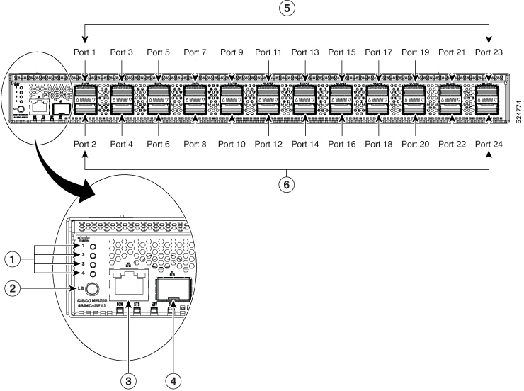
|
1 |
Lane Number Indicator |
2 |
Lane Select button |
|
3 |
Management Port (RJ45) |
4 |
Management Port (SFP) |
|
5 |
Port Numbering Scheme: Odd Numbers 12 x 40/100GE (QSFP28) for odd numbered ports only. Top row ports: 1,3,5,7,9,11,13,15,17,19,21,23 |
6 |
Port Numbering Scheme: Even Numbers 12 x 40/100GE (QSFP28) for even numbered ports only. Bottom row ports: 2,4,6,8,10,12,14,16,18,20,22,24 |
To determine which transceivers, adapters, and cables are support this switch, see the Cisco Transceiver Modules Compatibility Information document.
The figure shows the switch features on the power supply side of the chassis using AC power.
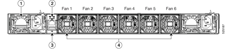
|
1 |
Power supply modules (1 or 2) (AC power supplies shown) with slots numbered 1 (left) and 2 (right) |
2 |
Console port RJ-45 |
|
3 |
USB 3.0 port |
4 |
NXA-SFAN-35CFM-PI Fan modules (6) with slots numbered from 1 (left) to 6 (right) |
Note |
The NXA-SFAN-35CFM-PE will be supported in a future release. |
The figure shows the side of the chassis.
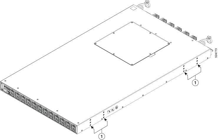
|
1 |
Screw holes for front mounting brackets (both left and right sides) |
The Cisco Nexus 9324C-SE1U switch can be mounted on a four-post (preferred) rack. The switch comes with a custom-mounting kit to allow for single-person installation. The system chassis dimensions are width: 17.3 in (43.94 cm); length: 30 in (76.2 cm); height: 1.72 in (4.36 cm).
The fan and power supply modules are field replaceable. You can replace one fan module or one power supply module during operations so long as the other modules are installed and operating. If you have only one power supply installed, you can install the replacement power supply in the open slot before removing the original power supply.
 Caution |
If the switch has port-side intake airflow (burgundy coloring for fan modules), you must locate the ports in the cold aisle. If the switch has port-side exhaust airflow (blue coloring for fan modules), you must locate the ports in the hot aisle. If you locate the air intake in a hot aisle, the switch can overheat and shut down. Currently, only port-side intake airflow is supported. Port-side exhaust will be available in a future release. |
 Feedback