LEDs

Switch Chassis LEDs

The BCN, STS, ENV, Port, and Lane Select LEDs are located on the left side of the front of the switch. The port LEDs appear as triangles pointing up or down to the nearest port. The Power Supply and Fan Module LEDs are located on the rear of the switch.
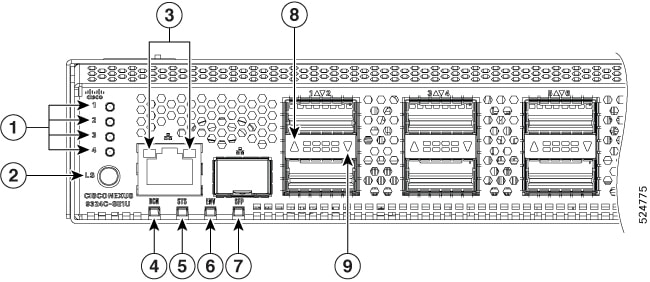
1

Lane Indicators

4

Beacon

7

SFP Act/Status

2

Lane Select Button

5

Status

8

Top QSFP port

3

RJ45 Act/Status

6

Environment

9

Bottom QSFP port

LED

Color

Status

BCN

Blue

The operator has activated this LED to identify this switch in the chassis.

Off

This switch is not being identified.

STS

Green

The switch is operational.

Flashing amber

The switch is booting up.

Amber

Temperature exceeds the minor alarm threshold.

Red

Temperature exceeds the major alarm threshold.

Off

The switch is not receiving power.

ENV

Green

Fans and power supply modules are operational.

Amber

At least one fan or power supply module is not operating.

(port)

Green

Port admin state is 'Enabled', SFP is present and the interface is connected (that is, cabled, and the link is up).

Amber

Port admin state is 'Disabled', or the SFP is absent, or both.

Off

Port admin state is 'Enabled' and SFP is present, but interface is not connected.

Lane Link LEDs

The Lane Link LEDs indicate which of the break out lanes are being checked. Use the Lane Select Button to select what number of the break-out lane status will be shown in the port LED. If none of the Lane Link LEDs is lit, all four lanes are being checked.

LED Lit Description

Fan Module LEDs

The fan module status LED is located above the air holes on the front of the fan module. Every fan module has an LED.

Table 1. Fan LED

Fan LED

Color

Status Description

Status

OFF

Fan tray is not receiving power

Amber

The fan is inserted into the system and pending to come on-line

Green

Fans are operating normally

Flashing Amber

This fan tray has failed

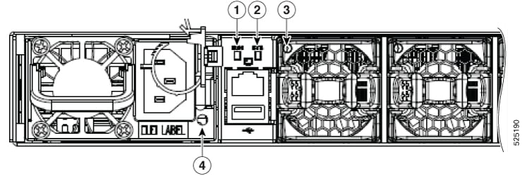
Figure 1. Cisco N9324C-SE1U Power Side Blowup

1

BCN LED

3

Fan LED

2

STS LED

4

Power Supply LED

Power Supply LEDs

The power supply LEDs are located on the right portion of the power supply. Combinations of states indicated by the OK and Fault LEDs signify the status for the module as shown in this table.

OK LED

FAIL or FAIL/ID LED

Status

Green

Off

Power supply is on and outputting power to the switch.

Flashing green

Off

Power supply is connected to a power source but not outputting power to the switch. The power supply may not be properly installed in the chassis.

Off

Off

Either all the installed power supplies are not receiving power or an uninstalled power supply is not receiving power.

Off

Flashing amber

Power supply is operating but a warning condition has occurred—possibly one of these conditions:

  • High temperature

  • High power

  • Slow power supply fan

  • Low voltage

  • Power supply is installed in the chassis but was disconnected from the power source.

Off

Flashing amber (10 seconds) then amber

Power supply is installed without a connection to a power source.

Off

Amber

Power supply failure—possibly one of these conditions:

  • Over voltage

  • Over current

  • Over temperature

  • Power supply fan failure

Color

Status/Description

Solid Green

Outputs 12V main and 12Vstby in regulation

2 Hz Blinking Green

AC input present and within operating range / Standby mode 12Vstby

4 Hz Blinking Green

Power Supply in boot loading mode

Solid Amber

Failure (no output) or one of these possible conditions:

  • AC input below operating range, but 12Vstby from a parallel unit,

  • Over voltage

  • Over current

  • Over temperature

  • OTP due to fan failure

1 HZ Blinking Amber

Power supply is operating but a warning condition has occurred—possibly one of these conditions:

  • High temperature

  • High power

  • Slow fan

Off

No out or AC input below operating range, no 12Vstby from a parallel unit.