Replacing a 4 (RU) Fan Module
The fan module is designed to be removed and replaced while the system is operating without causing an electrical hazard or damage to the system if the replacement is performed within one minute.
If you do not have the appropriate replacement fan module, leave the original fan module in its slot to preserve the designed airflow for the switch until you have the replacement fan module. The module number can be found on the chassis.
 Caution |
The fans might be turning when you remove the fan assembly from the chassis. Keep fingers, screwdrivers, and other objects away from the openings in the fan assembly's housing. |
Before you begin
-
Verify that you have an ESD wrist strap or other device to prevent ESD damage for components that you touch.
-
Verify that you have an antistatic surface or bag for placing the fan module that you remove from the chassis.
-
Verify that the replacement fan module has the correct direction of airflow (it has the same coloring as the other fan and power supply modules in the same chassis).
Procedure
|
Step 1 |
Attach an ESD wrist strap or other ESD device to your body and an earth ground to prevent ESD damage. You can attach the ESD device to any earth ground or grounded object, such as a grounded rack or ground connection on a chassis. |
|
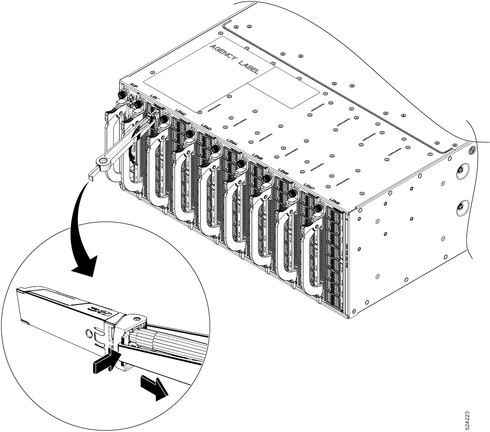
Step 2 |
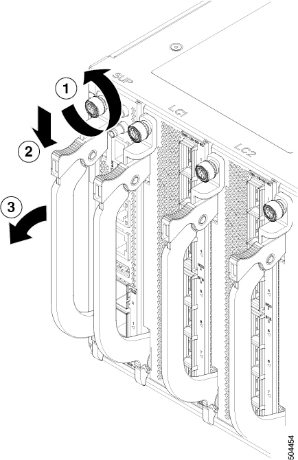
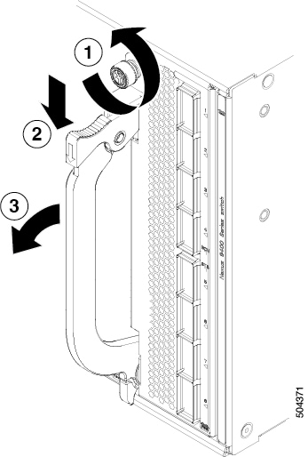
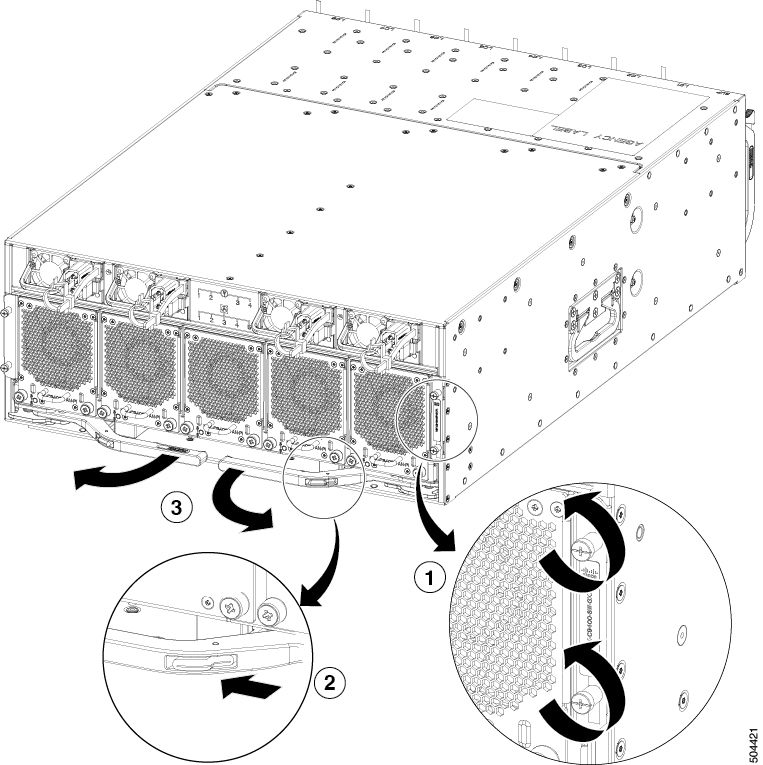
Remove the fan module that you are replacing as follows: |
|
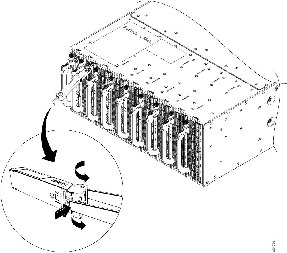
Step 3 |
Install the replacement fan module as follows:
|


 Feedback