Configuring IP Tunnels

This chapter contains the following sections:

Information About IP Tunnels

IP tunnels can encapsulate a same-layer or higher-layer protocol and transport the result over IP through a tunnel created between two devices.

IP tunnels consists of the following three main components:

  • Passenger protocol—The protocol that needs to be encapsulated. IPv4 is an example of a passenger protocol.

  • Carrier protocol—The protocol that is used to encapsulate the passenger protocol. Cisco NX-OS supports generic routing encapsulation (GRE), and IP-in-IP encapsulation and decapsulation as carrier protocols.

  • Transport protocol—The protocol that is used to carry the encapsulated protocol. IPv4 is an example of a transport protocol.

An IP tunnel takes a passenger protocol, such as IPv4, and encapsulates that protocol within a carrier protocol, such as GRE. The device then transmits this carrier protocol over a transport protocol, such as IPv4.

You configure a tunnel interface with matching characteristics on each end of the tunnel.

You must enable the tunnel feature before you can configure it.

GRE Tunnels

You can use GRE as the carrier protocol for a variety of passenger protocols. The selection of tunnel interfaces can also be based on the PBR policy.

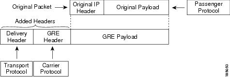
The figure shows the IP tunnel components for a GRE tunnel. The original passenger protocol packet becomes the GRE payload and the device adds a GRE header to the packet. The device then adds the transport protocol header to the packet and transmits it.

Figure 1. GRE PDU


Point-to-Point IP-in-IP Tunnel Encapsulation and Decapsulation

Point-to-point IP-in-IP encapsulation and decapsulation is a type of tunnel that you can create to send encapsulated packets from a source tunnel interface to a destination tunnel interface. The selection of these tunnel interfaces can also be based on the PBR policy. This type of tunnel will carry both inbound and outbound traffic.

Multi-Point IP-in-IP Tunnel Decapsulation

Multi-point IP-in-IP decapsulate-any is a type of tunnel that you can create to decapsulate packets from any number of IP-in-IP tunnels to one tunnel interface. This tunnel will not carry any outbound traffic. However, any number of remote tunnel endpoints can use a tunnel configured this way as their destination.

Prerequisites for IP Tunnels

IP tunnels have the following prerequisites:

  • You must be familiar with TCP/IP fundamentals to configure IP tunnels.

  • You are logged on to the switch.

  • You have installed the Enterprise Services license for Cisco NX-OS.

  • You must enable the tunneling feature in a device before you can configure and enable any IP tunnels.

Guidelines and Limitations for IP Tunnels

IP tunnels have the following configuration guidelines and limitations:

  • Guidelines for source-direct and ipv6ipv6-decapsulate-any options for tunnels:

    • The tunnel source direct command is supported only when an administrator uses the IP-in-IP decapsulation to source route the packets through the network. The source-direct tunnel is always operationally Up unless it is administratively shut down. The directly connected interfaces are identified using the show ip route direct command.

    • The tunnel source direct command is supported only on decapsulate-any tunnel modes, for example, tunnel mode ipip decapsulate-any and tunnel mode ipv6ipv6 decapsulate-any .

    • Auto-recovery is not supported for source-direct.

    • For ipv6ipv6 decapsulate-any , inter-VRF is not supported. The tunnel interface VRF (iVRF) and tunnel transport or forwarding VRF (fVRF) must be the same. Only one decapsulate-any tunnel (irrespective of VRF) can be present in Cisco Nexus 3000 Series switches.

    • To enable IPv6 on ipv6ipv6 decap-any tunnel interface, you must configure a valid IPv6 address or configure the ipv6 address using use-link-local-only CLI command under the interface tunnel interface.

  • The hardware limitations on a source direct tunnel are as follows:

    • Source direct tunnel supports Cisco Nexus 3000 Series switches with Network Forwarding Engine (NFE), Application Spine Engine (ASE), and Leaf Spine Engine (LSE). There are limitations in cases of scaled SIP (number of total IP/IPv6 addresses on the interfaces (L3, sub-interface, PC, PC-sub interfaces, loopback, SVI, and any secondary IP/IPv6 addresses.)

      See the following sample use cases.

      • Use Case 1: Non-deterministic behavior of which SIP gets installed if the number of IP/IPv6 interface scale is more.

        Both the switches have 512 entries for tunnel SIP. With tunnel source, direct any IP or IPv6 address w.r.t ipip or ipv6ipv6 decap any with tunnel source gets installed in the above table.

        The insertion of these entries is on a first come first serve basis without any CLI command to control which interface IP addresses get installed. If the system has more number of IP/IPv6 interfaces to be installed, the behavior is non-deterministic (The behavior can change across reload with interface flaps.)

      • Use Case 2: The scale numbers are different in both switches and each has its own advantages and disadvantages.

        IPv4 individual scale can be more (up to 512) in case of switches with NFE. In the switches with ASE and LSE, the IPv4 individual scale can be 256 but it is shared with IPv6. If the user plans to configure both v4 and v6 decap any tunnel in the same system, the scale numbers for the switches with NFE for individual IPv4 and IPv6 cannot be guaranteed. However, the scale numbers for the switches with ASE and LSE for individual IPv4 and IPv6 are guaranteed. These is no CLI command to change these pre-carved scale numbers, for example, allocating X for IPv4 and Y for IPv6.

        Whenever the tunnel decap table gets full, the TABLE_FULL error is displayed. If an entry gets deleted after the table is full, the table full error is cleared.

        If the tunnel-decap-table is full, the user gets a syslog similar to as follows:

        
         2017 Apr 26 10:10:51 switch %$ VDC-1 %$ %IPFIB-2-FIB_HW_IP_TUNNEL_DECAP_TABLE_FULL: 
        IP TUNNEL decap hardware table full. IP tunnel decapsulation may not work for some GRE/IPinIP traffic
          

        If the table is full and if an entry is deleted from the table because of an interface being operationally down or removal of IP address, the clear syslog for the table is displayed. Deleting of a tunnel removes all the entries that are added as part of that tunnel.

        
         2002 Sep 26 10:11:37 switch %$ VDC-1 %$ 
        %IPFIB-2-FIB_HW_IP_TUNNEL_DECAP_TABLE_FULL_CLRD: IP TUNNEL decap hardware table 
        full exception cleared
          
      • Table 1. Scale Numbers

        Commands

        Switches with NFE: Table size 512, v4 takes 1 entry, v6 takes 4 entries

        Switches with ASE and LSE: Table size 512, v4 takes 1 entry, v6 takes 2 entries (paired index)

        IPIP decap any with tunnel source direct

        Shared between v4 and v6, v6 takes 4 entries

        v4 + 4 *v6 =512

        Maximum entries can be 512 with no v6 entries

        Dedicated 256

        IPv6IPv6 decap any with tunnel source direct

        Shared between v4 and v6, v6 takes 4 entries

        v4 + 4 *v6 =512

        Maximum entries can be 128 with no v4 entries

        Dedicated 128

      • Use Case 3: Auto-recovery is not supported.

        If any entry does not get installed in the hardware due to exhaustion of above table, removal of an already installed IP/IPv6 from interfaces does not automatically trigger the addition of the failed SIP in the table though the table has space now. You need to flap the tunnel interface or IP interface to get them installed.

        However, if an entry does not get installed in the hardware due to a duplicate entry (if there was already a decap-any with one source present and now the source direct tunnel CLI command is configured, there is a duplicate entry for the prior source configured) that was taken care of by removing the entry only when both the tunnels get deleted.

  • interface loopback0
      ip address 2001:0:0:4::1/128
    !
    interface Tunnel 1
      ipv6 address use-link-local-only
      tunnel mode tunnel mode ipv6ipv6 decapsulate-any
      tunnel source loopback0
      description IPinIP Decapsulation Interface
      mtu 1476
      no shutdown
  • Cisco NX-OS software supports the GRE header defined in IETF RFC 2784. Cisco NX-OS software does not support tunnel keys and other options from IETF RFC 1701.

  • The Cisco Nexus device supports the following maximum number tunnels:

    • GRE and IP-in-IP regular tunnels-8 tunnels

    • Multipoint IP-in-IP tunnels-32 tunnels

  • Each tunnel will consume one Equal Cost Multipath (ECMP) adjacency.

  • The Cisco Nexus device does not support the following features:
    • Path maximum transmission unit (MTU) discovery

    • Tunnel interface statistics

    • Access control lists (ACLs)

    • Unicast reverse path forwarding (URPF)

    • Multicast traffic and associated multicast protocols such as Internet Group Management Protocol (IGMP) and Protocol Independent Multicast (PIM)

  • Cisco NX-OS software does not support the Web Cache Control Protocol (WCCP) on tunnel interfaces.

  • Cisco NX-OS software supports only Layer-3 traffic.

  • Cisco NX-OS software supports ECMP across tunnels and ECMP for tunnel destination.

  • IPv6-in-IPv6 tunnels is not supported.

  • Limited control protocols, such as Border Gateway Protocol (BGP), Open Shortest Path First (OSPF), and Enhanced Interior Gateway Routing Protocol (EIGRP), are supported for GRE tunnels.

  • Starting with Release 6.0(2)U5(1), Cisco Nexus 3000 Series switches drop all the packets when the tunnel is not configured. The packets are also dropped when the tunnel is configured but the tunnel interface is not configured or the tunnel interface is in shut down state.

    Point to Point tunnel (Source and Destination) – Cisco Nexus 3000 Series switches decapsulate all IP-in-IP packets destined to it when the command feature tunnel is configured and there is an operational tunnel interface configured with the tunnel source and the destination address that matches the incoming packets' outer source and destination addresses. If there is not a source and destination packet match or if the interface is in shutdown state, the packet is dropped.

    Decapsulate Tunnel (Source only) - Cisco Nexus 3000 Series switches decapsulate all IP-in-IP packets destined to it when the command feature tunnel is configured and there is an operational tunnel interface configured with the tunnel source address that matches the incoming packets' outer destination addresses. If there is not a source packet match or if the interface is in shutdown state, the packet is dropped.

  • Starting with Release 6.0(2)U6(1), Cisco Nexus 3000 Series switches support IPv6 in IPv4 with GRE header only. The new control protocols that are supported on the tunnel are:
    • BGP with v6

    • OSPFv3

    • EIGRP over v6

  • GRE v4/v6 tunnel configuration is supported only in the default routing mode. It does not support the multicast traffic or multicast protocols, for example, IGMP/PIM. It does not support ACL/QoS policies. It supports a maximum of 8 tunnels in the switch, whether they are all IPinIP or GRE; or any combination of both. The packets that are sent/received over the tunnel and that are destined for the switch, are not counted in the tunnel statistics.

  • The Cisco Nexus 3000 Series switches ASIC supports the GRE encapsulation and decapsulation in the hardware.

  • On the encapsulation side, the Cisco Nexus 3000 Series switches performs a single lookup in the hardware.

  • Since Cisco Nexus 3000 Series switches perform a single lookup in the hardware, the software has to keep the hardware information up-to-date with any changes related to the second lookup, for example, the tunnel destination adjacency.

  • On the decapsulation side, the Cisco Nexus 3000 Series switches have a separate table to perform the outer IP header lookup and it does not need an ACL for the same.

  • RFC5549 is not supported over tunnels.

Default Settings for IP Tunneling

The following table lists the default settings for IP tunnel parameters.

Table 2. Default IP Tunnel Parameters

Parameters

Default

Tunnel feature

Disabled

Configuring IP Tunnels

Enabling Tunneling

Before you begin

You must enable the tunneling feature before you can configure any IP tunnels.

Procedure

  Command or Action Purpose
Step 1

switch# configure terminal

Enters global configuration mode.

Step 2

switch(config)# feature tunnel

Enables the tunnel feature on the switch.

Step 3

switch(config)# exit

Returns to configuration mode.

Step 4

switch(config)# show feature

Displays the tunnel feature on the switch.

Step 5

(Optional) switch# copy running-config startup-config

(Optional)

Saves the change persistently through reboots and restarts by copying the running configuration to the startup configuration.

Example

This example shows how to enable the tunnel feature:

switch# configure terminal
switch(config)# feature tunnel
switch(config)# exit
switch(config)# copy running-config startup-config

Creating a Tunnel Interface

You can create a tunnel interface and then configure this logical interface for your IP tunnel. GRE mode is the default tunnel mode.

Before you begin

Both the tunnel source and the tunnel destination must exist within the same virtual routing and forwarding (VRF) instance.

Ensure that you have enabled the tunneling feature.

Procedure

  Command or Action Purpose
Step 1

switch# configure terminal

Enters global configuration mode.

Step 2

switch(config)# [no] interface tunnel number

Creates a new tunnel interface.

Step 3

switch(config)# tunnel mode {gre ip | ipip {ip | decapsulate-any}}

Sets this tunnel mode to GRE, ipip, or ipip decapsulate-only.

The gre and ip keywords specify that GRE encapsulation over IP will be used.

The ipip keyword specifies that IP-in-IP encapsulation will be used. The optional decapsulate-any keyword terminates IP-in-IP tunnels at one tunnel interface. This keyword creates a tunnel that will not carry any outbound traffic. However, remote tunnel endpoints can use a tunnel configured as their destination.

Step 4

switch(config)# tunnel source {ip address | interface-name}

Configures the source address for this IP tunnel.

Step 5

switch(config)# tunnel destination {ip address | host-name}

Configures the destination address for this IP tunnel.

Step 6

(Optional) switch(config)# tunnel use-vrf vrf-name

(Optional)

Uses the configured VRF instance to look up the tunnel IP destination address.

Step 7

(Optional) switch(config)# show interface tunnel number

(Optional)

Displays the tunnel interface statistics.

Step 8

(Optional) switch# copy running-config startup-config

(Optional)

Saves the change persistently through reboots and restarts by copying the running configuration to the startup configuration.

Example

This example shows how to create a tunnel interface:

switch# configure terminal
switch(config)# interface tunnel 1
switch(config)# tunnel source ethernet 1/2
switch(config)# tunnel destination 192.0.2.1 
switch(config)# copy running-config startup-config

Configuring a Tunnel Interface

The tunnel mode ipv6ipv6 decapsulate-any command supports IPv6 payload over IPv6 transport (IPv6inIPv6 packets). You can configure IP-in-IP tunnel decapsulation on directly connected IP addresses (for example, physical interface, port-channel, loopback, and SVI) using the new tunnel source direct CLI command.

Before you begin

Ensure that you have enabled the tunneling feature.

Procedure

  Command or Action Purpose
Step 1

configure terminal

Example:

switch# configure terminal
switch(config)#

Enters global configuration mode.

Step 2

interface tunnel number

Example:

switch(config)# interface tunnel 1
switch(config-if)#

Creates a new tunnel interface.

Step 3

tunnel mode {gre ip | ipip | {ip | decapsulate-any}}

Sets this tunnel mode to GRE, ipip, or ipip decapsulate-only.

The gre and ip keywords specify that GRE encapsulation over IP will be used.

The ipip keyword specifies that IP-in-IP encapsulation will be used. The optional decapsulate-any keyword terminates IP-in-IP tunnels at one tunnel interface. This keyword creates a tunnel that will not carry any outbound traffic. However, remote tunnel endpoints can use a tunnel configured as their destination.

Step 4

(Optional) tunnel mode ipv6ipv6 decapsulate-any

(Optional)

Supports IPv6 payload over IPv6 transport (IPv6inIPv6 packets) This step is applicable for IPv6 networks only.

Step 5

tunnel source direct

Configures IP-in-IP tunnel decapsulation on any directly connected IP addresses. this option is now supported only when the IP-in-IP decapsulation is used to source route the packets through the network.

Step 6

show interfaces tunnel number

Example:

switch(config-if)# show interfaces tunnel 1

(Optional) Displays the tunnel interface statistics.

Step 7

mtu value

Sets the maximum transmission unit (MTU) of IP packets sent on an interface.

The range is from 64 to 9192 units.

Step 8

copy running-config startup-config

Example:

switch(config-if)# copy running-config
startup-config

(Optional) Saves this configuration change.

Example

This example shows how to create the tunnel interface to GRE:

switch# configure terminal
switch(config)# interface tunnel 1
switch(config-if)# tunnel mode gre ip
switch(config-if)# copy running-config startup-config

This example shows how to create an ipip tunnel:

switch# configure terminal
switch(config)# interface tunnel 1
switch(config-if)# tunnel mode ipip
switch(config-if)# mtu 1400
switch(config-if)# copy running-config startup-config
switch(config-if)# no shut

This example shows how to configure IP-in-IP tunnel decapsulation on directly connected IP addresses:

switch# configure terminal
switch(config)# interface tunnel 0
switch(config-if)# tunnel mode ipip ip
switch(config-if)# tunnel source direct
switch(config-if)# description IPinIP Decapsulation Interface
switch(config-if)# no shut

This example shows how to configure IP-in-IP tunnel decapsulation on IPv6 enabled networks:

interface loopback0
  ip address 2001:0:0:4::1/128
!
interface Tunnel1
  tunnel mode ipip decapsulate-any ipv6
  tunnel source loopback0
  description IPinIP Decapsulation Interface
  mtu 1476
  no shutdown

show running-config interface tunnel 1
interface Tunnel1
  tunnel mode ipv6ipv6 decapsulate-any
  tunnel source direct
  no shutdown

show interface tunnel 1
Tunnel1 is up    Admin State: up    
MTU 1460 bytes, BW 9 Kbit    
Tunnel protocol/transport IPv6/DECAPANY/IPv6    
Tunnel source - direct    
Transport protocol is in VRF "default"    
Tunnel interface is in VRF "default"    
Last clearing of "show interface" counters never    
Tx    0 packets output, 0 bytes    Rx    0 packets input, 0 bytes

Configuring a Tunnel Interface Based on Policy Based Routing

You can create a tunnel interface and then configure this logical interface for your IP tunnel based on the PBR policy.

Before you begin

Ensure that you have enabled the tunneling feature.

Procedure

  Command or Action Purpose
Step 1

switch# configure terminal

Enters global configuration mode.

Step 2

switch(config)# [no] interface tunnel number

Creates a new tunnel interface.

Step 3

switch(config)# ip address ip address

Configures an IP address for this interface.

Step 4

switch(config)# route-map map-name

Assigns a route map for IPv4 policy-based routing to the interface

Step 5

switch(config-route-map)# match ip address access-list-name name

Matches an IPv4 address against one or more IP access control lists (ACLs). This command is used for policy-based routing and is ignored by route filtering or redistribution.

Step 6

switch(config-route-map)# set ip next-hop address

Sets the IPv4 next-hop address for policy-based routing. To select tunnel interfaces, you must specify the Tunnel IP addresses as next-hop addresses. This command uses the first valid next-hop address if multiple addresses are configured. Use the load-share option to select ECMP across next-hop entries.

Example

This example shows how to configure a tunnel interface that is based on PBR:

switch# configure terminal
switch(config)# interface tunnel 1
switch(config)# ip address 1.1.1.1/24
switch(config)# route-map pbr1
switch(config-route-map)# match ip address access-list-name pbr1
switch(config-route-map)# set ip next-hop 1.1.1.1

Configuring a GRE Tunnel

GRE v6 tunnel is used to carry different types of packets over IPv6 transport. GREv6 tunnel carries only IPv4 payload. The tunnel CLIs are enhanced to select IPv6 tunnel and configure v6 tunnel source and destination.

You can set a tunnel interface to GRE tunnel mode, ipip mode, or ipip decapsulate-only mode. GRE mode is the default tunnel mode. Starting with Release 6.0(2)U6(1), Cisco Nexus 3000 Series switches support IPv6 payload over IPv4 tunnel with GRE header only.

Before you begin

Ensure that you have enabled the tunneling feature.

Procedure

  Command or Action Purpose
Step 1

switch# configure terminal

Enters global configuration mode.

Step 2

switch(config)# interface tunnel number

Enters a tunnel interface configuration mode.

Step 3

switch(config-if)# tunnel mode {gre ip | ipip {ip | decapsulate-any}}

Sets this tunnel mode to GRE, ipip, or ipip decapsulate-only.

The gre and ip keywords specify that GRE encapsulation over IP will be used.

The ipip keyword specifies that IP-in-IP encapsulation will be used. The optional decapsulate-any keyword terminates IP-in-IP tunnels at one tunnel interface. This keyword creates a tunnel that will not carry any outbound traffic. However, remote tunnel endpoints can use a tunnel configured as their destination.

Step 4

switch(config-if)# tunnel use-vrf vrf-name

Configures tunnel VRF name.

Step 5

switch(config-if)# ipv6 address IPv6 address

Configures the IPv6 address.

Note 

The tunnel source and the destination addresses are still the same (IPv4 address.)

Step 6

(Optional) switch(config-if)# show interface tunnel number

(Optional)

Displays the tunnel interface statistics.

Step 7

switch(config-if)# mtu value

Sets the maximum transmission unit (MTU) of IP packets sent on an interface.

Step 8

(Optional) switch(config-if)# copy running-config startup-config

(Optional)

Saves the change persistently through reboots and restarts by copying the running configuration to the startup configuration.

Example

This example displays how to configure IPv6 Payload over GRE v4 tunnel. Configure the tunnel source, destination, IPv4 address, IPv6 address, and perform the no shut command. Once the GREv4 tunnel is created, you can configure v4 or v6 route via the tunnel:

switch# configure terminal
switch(config)# interface tunnel 10
switch(config)# tunnel source 11.1.1.1
switch(config)# tunnel destination 11.1.1.2
switch(config-if)# tunnel mode gre ip
switch(config-if)# tunnel use-vrf red
switch(config-if)# ip address 10.1.1.1/24
switch(config-if)# ipv6 address 2:2::2/64
switch(config-if)# no shut

switch(config)# ip route 50.1.1.0/24 tunnel 10
switch(config)# ipv6 route 2000:100::/64 tunnel 10

This example shows how to view the GRE v4 tunnel interface 10 and display IPv4 and IPv6 routes:

switch(config)# show int tunnel 10
Tunnel 10 is up
    Admin State: up 
    Internet address(es): 
    10.1.1.1/24        
    1010::1/64                                   
    MTU 1476 bytes, BW 9 Kbit
    Tunnel protocol/transport GRE/IP
    Tunnel source 11.1.1.1, destination 11.1.1.2
    Transport protocol is in VRF "default"

switch#show ipv6 route
…
2000:100::/64, ubest/mbest: 1/0, attached
    *via Tunnel10, [1/0], 00:00:16, static

#show ip route
…
50.1.1.0/24, ubest/mbest: 1/0
    *via Tunnel10, [1/0], 00:03:33, static

This example displays how to configure IPv4 payload over GRE v6 tunnel. Configure the tunnel mode as GRE IPv6, tunnel v6 source and destination, IPv4 address, and perform the no shut command. Once the GREv6 tunnel is created, you can configure v4 route via the tunnel:

switch# configure terminal
switch(config)# interface tunnel 20
switch(config-if)# tunnel mode gre ipv6
switch(config)# tunnel source 1313::1
switch(config)# tunnel destination 1313::2
switch(config-if)# tunnel use-vrf red
switch(config-if)# ip address 20.1.1.1/24
switch(config-if)# no shut

switch(config)# ip route 100.1.1.0/24 tunnel 20

This example displays how to view the GREv6 tunnel interface 20:

show interface tunnel 20
Tunnel 20 is up
    Admin State: up 
    Internet address is 20.1.1.1/24        
    MTU 1456 bytes, BW 9 Kbit
    Tunnel protocol/transport GRE/IPv6
    Tunnel source 1313::1, destination 1313::2
    Transport protocol is in VRF "default"

#show ip route
…
100.1.1.0/24, ubest/mbest: 1/0
    *via Tunnel20, [1/0], 00:01:00, static

red10# show interface brief | grep Tunnel
Tunnel10                 up         10.1.1.1/24       GRE/IP           1476    
Tunnel20                 up         20.1.1.1/24       GRE/IPv6         1456

This example shows how to create an ipip tunnel:

switch# configure terminal
switch(config)# interface tunnel 1
switch(config-if)# tunnel mode ipip
switch(config-if)# mtu 1400
switch(config-if)# copy running-config startup-config
switch(config-if)# no shut

Assigning VRF Membership to a Tunnel Interface

You can add a tunnel interface to a VRF.

Before you begin

Ensure that you have enabled the tunneling feature.

Assign the IP address for a tunnel interface after you have configured the interface for a VRF.

Procedure

  Command or Action Purpose
Step 1

switch# configure terminal

Enters global configuration mode.

Step 2

switch(config)# interface tunnel number

Enters interface configuration mode.

Step 3

switch(config)# vrf member vrf-name

Adds this interface to a VRF.

Step 4

switch(config)# ip address ip-prefix/length

Configures an IP address for this interface. You must do this step after you assign this interface to a VRF.

Step 5

(Optional) switch(config)# show vrf [vrf-name] interface interface-type number

(Optional)

Displays VRF information.

Step 6

(Optional) switch(config-if)# copy running-config startup-config

(Optional)

Saves the change persistently through reboots and restarts by copying the running configuration to the startup configuration.

Example

This example shows how to add a tunnel interface to the VRF:

switch# configure terminal
switch(config)# interface tunnel 0
switch(config-if)# vrf member RemoteOfficeVRF
switch(config-if)# ip address 209.0.2.1/16
switch(config-if)# copy running-config startup-config

Verifying the IP Tunnel Configuration

Use the following commands to verify the configuration:

Command Purpose

show interface tunnel number

Displays the configuration for the tunnel interface (MTU, protocol, transport, and VRF). Displays input and output packets, bytes, and packet rates.

show interface tunnel number brief

Displays the operational status, IP address, encapsulation type, and MTU of the tunnel interface.

show interface tunnel number description

Displays the configured description of the tunnel interface.

show interface tunnel number status

Displays the operational status of the tunnel interface.

show interface tunnel number status err-disabled

Displays the error disabled status of the tunnel interface.

Configuration Examples for IP Tunneling

This example shows a simple GRE tunnel. Ethernet 1/2 is the tunnel source for router A and the tunnel destination for router B. Ethernet interface 1/3 is the tunnel source for router B and the tunnel destination for router A.

router A:
feature tunnel
interface tunnel 0
  ip address 209.165.20.2/8
  tunnel source ethernet 1/2
  tunnel destination 192.0.2.2
  tunnel mode gre ip
interface ethernet1/2
  ip address 192.0.2.55/8

router B:
feature tunnel 
interface tunnel 0
  ip address 209.165.20.1/8
  tunnel source ethernet 1/3
  tunnel destination 192.0.2.55
  tunnel mode gre ip
interface ethernet 1/3
ip address 192.0.2.2/8

Related Documents for IP Tunnels

Related Topics Document Title

IP tunnel commands

Cisco Nexus 3000 Series Interfaces Command Reference

Standards for IP Tunnels

No new or modified standards are supported by this feature, and support for existing standards has not been modified by this feature.

Feature History for Configuring IP Tunnels

Table 3. Feature History for Configuring IP Tunnels

Feature Name

Release

Feature Information

Multi-point and Point-to-Point IP-in-IP encapsulation and decapsulation

6.0(2)U2(1)

Support for these tunnel modes was added.

IP tunnels

5.0(3)U4(1)

This feature was introduced.