Configuring iSCSI Multipath

This chapter contains the following sections:

Information About iSCSI Multipath

This section includes the following topics:

  • Overview

  • Supported iSCSI Adapters

  • iSCSI Multipath Setup on the VMware SwitchVirtual Switch

Overview

The iSCSI multipath feature sets up multiple routes between a server and its storage devices for maintaining a constant connection and balancing the traffic load. The multipathing software handles all input and output requests and passes them through on the best possible path. Traffic from host servers is transported to shared storage using the iSCSI protocol that packages SCSI commands into iSCSI packets and transmits them on the Ethernet network.

iSCSI multipath provides path failover. In the event a path or any of its components fails, the server selects another available path. In addition to path failover, multipathing reduces or removes potential bottlenecks by distributing storage loads across multiple physical paths.

The daemon on an KVM server communicates with the iSCSI target in multiple sessions using two or more Linux kernel NICs on the host and pinning them to physical NICs on the Cisco Nexus 1000V. Uplink pinning is the only function of multipathing provided by the Cisco Nexus 1000V. Other multipathing functions such as storage binding, path selection, and path failover are provided by code running in the Linux kernel.

Setting up iSCSI Multipath is accomplished in the following steps:

  1. Uplink Pinning

    Each Linux kernel port created for iSCSI access is pinned to one physical NIC. This overrides any NIC teaming policy or port bundling policy. All traffic from the Linux kernel port uses only the pinned uplink to reach the upstream switch.

  2. Storage Binding

    Each Linux kernel port is pinned to the iSCSI host bus adapter (VMHBA) associated with the physical NIC to which the Linux kernel port is pinned.

    The ESX or ESXi host creates the following VMHBAs for the physical NICs.

    • In Software iSCSI, only one VMHBA is created for all physical NICs.

    • In Hardware iSCSI, one VMHBA is created for each physical NIC that supports iSCSI offload in hardware.

For detailed information about how to use sn iSCSI storage area network (SAN), see the iSCSI SAN Configuration Guide.

Supported iSCSI Adapters

The default settings in the iSCSI Multipath configuration are listed in the following table.

Parameter

Default

Type (port-profile)

vEthernet

Description (port-profile)

None

Linux port group name (port-profile)

The name of the port profile

Switchport mode (port-profile)

Access

State (port-profile)

Disabled

iSCSI Multipath Setup on the VMware Switch

Before enabling or configuring multipathing, networking must be configured for the software or hardware iSCSI adapter. This involves creating a Linux kernel iSCSI port for the traffic between the iSCSI adapter and the physical NIC.

Uplink pinning is done manually by the admin directly on the OpenStack controller.

Storage binding is also done manually by the admin directly on the KVM host or using RCLI.

For software iSCSI, only oneVMHBA is required for the entire implementation. All Linux kernel ports are bound to this adapter. For example, in the following illustration, both vmk1 and vmk2 are bound to VMHBA35.

For hardware iSCSI, a separate adapter is required for each NIC. Each Linux kernel port is bound to the adapter of the physical KVM NIC to which it is pinned. For example, in the following illustration, vmk1 is bound to VMHBA33, the iSCSI adapter associated with vmnic1 and to which vmk1 is pinned. Similarly vmk2 is bound to VMHBA34.
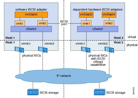
Figure 1. iSCSI Multipathing


The following are the adapters and NICs used in the hardware and software iSCSI multipathing configuration shown in the iSCSI Multipath illustration.

Software HBA

Linux kernel NIC

KVM NIC

VMHBA35

1

1

2

2

Hardware HBA

VMHBA33

1

1

VMHBA34

2

2

Guidelines and Limitations

The following are guidelines and limitations for the iSCSI multipath feature:

  • Only port profiles of type vEthernet can be configured with capability iscsi-multipath .

  • The port profile used for iSCSI multipath must be an access port profile, not a trunk port profile.

  • The following are not allowed on a port profile configured with capability iscsi-multipath:

    • The port profile cannot also be configured with capability l3 control

    • A system VLAN change when the port profile is inherited by VMkernel NIC.

    • An access VLAN change when the port profile is inherited by VMkernel NIC.

    • A port mode change to trunk mode.

  • Only VMkernel NIC ports can inherit a port profile configured with capability iscsi-multipath capability iscsi-multipath.

  • The Cisco Nexus 1000V imposes the following limitations if you try to override its automatic uplink pinning.

    • A VMkernel port can only be pinned to one physical NIC.

    • Multiple VMkernel ports can be pinned to a software physical NIC.

    • Only one VMkernel port can be pinned to a hardware physical NIC.

  • The iSCSI initiators and storage must already be operational.

  • VMkernel ports must be created before enabling or configuring the software or hardware iSCSI for multipathing.

  • VMkernel networking must be functioning for the iSCSI traffic.

  • Before removing from the DVS an uplink to which an activeVMkernel NIC is pinned, you must first remove the binding between the VMkernel NIC and its VMHBA. The following system message displays as a warning:

    vsm# 2010 Nov 10 02:22:12 sekrishn-bl-vsm %VEM_MGR-SLOT8-1-VEM_SYSLOG_ALERT: sfport : Removing Uplink Port Eth8/3 (ltl 19), when vmknic lveth8/1 (ltl 49) is pinned to this
     port for iSCSI Multipathing
  • Hardware iSCSI is new in Cisco Nexus 1000V Release 4.2(1)SV1(5.1). If you configured software iSCSI multipathing in a previous release, the following are preserved after upgrade:

    • multipathing

    • software iSCSI uplink pinning

    • VMHBA adapter bindings

    • host access to iSCSI storage

      To leverage the hardware offload capable NICs on ESX 5.1, use the Converting to a Hardware iSCSI Configuration procedure.

  • An iSCSI target and initiator should be in the same subnet.

  • iSCSI multipathing on the Nexus 1000V currently only allows a single vmknic to be pinned to one vmnic.

Pre-requisites

The iSCSI Multipath feature has the following prerequisites:

  • You must understand VMware iSCSI SAN storage virtualization. For detailed information about how to use VMware ESX and VMware ESXi systems with an iSCSI storage area network (SAN), see the iSCSI SAN Configuration Guide.

  • You must know how to set up the iSCSI Initiator on your VMware ESX/ESXi host.

  • The host is already functioning with one of the following:

    • VMware ESX 5.0 for software iSCSI

    • VMware ESX 5.1 or later for software and hardware iSCSI

  • You must understand iSCSI multipathing and path failover.

  • VMware kernel NICs configured to access the SAN external storage are required.

Default Settings

Parameters

Default

Type (port-profile)

vEthernet

Description (port-profile)

None

VMware port group name (port-profile)

The name of the port profile

Switchport mode (port-profile)

Access

State (port-profile)

Disabled

Configuring iSCSI Multipath

Use the following procedures to configure iSCSI Multipath:

  • Uplink Pinning and Storage Binding procedure

  • Converting to a Hardware iSCSI Configuration procedure

  • Changing the VMkernel NIC Access VLAN procedure

Uplink Pinning and Storage Binding

Use this section to configure iSCSI multipathing between hosts and targets over iSCSI protocol by assigning the vEthernet interface to an iSCSI multipath port profile configured with a system VLAN.

Process for Uplink Pinning and Storage Binding

Refer to the following process for Uplink Pinning and Storage Binding:

  • Creating a Port Profile for a VMkernel NIC procedure.

  • Creating VMkernel NICs and Attaching the Port Profile procedure.

Do one of the following:

  • If you want to override the automatic pinning of NICS, go to Manually Pinning the NICs procedure.

  • If not, continue with storage binding.

  • You have completed uplink pinning. Continue with the next step for storage binding.

  • Identifying the iSCSI Adapters for the Physical NICs procedure.

  • Binding the VMkernel NICs to the iSCSI Adapter procedure.

  • Verifying the iSCSI Multipath Configuration procedure.

Creating a Port Profile for a VMkernel NIC

You can use this procedure to create a port profile for a VMkernel NIC.

Before you begin

Before starting this procedure, you must know or do the following:

  • You have already configured the host with one port channel that includes two or more physical NICs

  • Multipathing must be configured on the interface by using this procedure to create an iSCSI multipath port profile and then assigning the interface to it.

  • You are logged in to the CLI in EXEC mode.

  • You know the VLAN ID for the VLAN you are adding to this iSCSI multipath port profile.

    • The VLAN must already be created on the Cisco Nexus 1000V.

    • The VLAN that you assign to this iSCSI multipath port profile must be a system VLAN.

    • One of the uplink ports must already have this VLAN in its system VLAN range.

  • The port profile must be an access port profile. It cannot be a trunk port profile. This procedure includes steps to configure the port profile as an access port profile.

Procedure

  Command or Action Purpose
Step 1

switch# configure terminal

Places you in global configuration mode.

Step 2

switch(config)# port-profile type vethernet name

Places you into the CLI Port Profile Configuration mode for the specified port profile.

type: Defines the port-profile as Ethernet or vEthernet type. Once configured, this setting cannot be changed. The default is vEthernet type.

If a port profile is configured as an Ethernet type, then it cannot be used to configure VMware virtual ports.

name: The port profile name can be up to 80 characters and must be unique for each port profile on the Cisco Nexus 1000V.

Step 3

switch(config)# description profile description

Adds a description to the port profile. This description is automatically pushed to the vCenter Server.

profile description: up to 80 ASCII characters. If the description includes spaces, it must be surrounded by quotations.

Step 4

switch(config)# vmware port-group name

Designates the port-profile as a VMware port group. The port profile is mapped to a VMware port group of the same name. When a vCenter Server connection is established, the port group created in Cisco Nexus 1000V is then distributed to the virtual switch on the vCenter Server. name: The Vmware port group name.If you want to map the port profile to a different port group name, use the alternate name.

Step 5

switch(config)# switchport mode access

Designates that the interfaces are switch access ports (the default).

Step 6

switch(config)# switchport access vlan vlanID

Assigns the system VLAN ID to the access port for this port profile. The VLAN assigned to this iSCSI port profile must be a system VLAN.

Step 7

switch(config)# no shutdown

Administratively enables all ports in the profile.

Step 8

switch(config)# system vlan vlanID

Adds the system VLAN to this port profile. This ensures that, when the host is added for the first time or rebooted later, the VEM will be able to reach the VSM. One of the uplink ports must have this VLAN in its system VLAN range.

Step 9

switch(config)# capability iscsi-multipath

Allows the port to be used for iSCSI multipathing. In vCenter Server, the iSCSI Multipath port profile must be selected and assigned to the VMkernel NIC port.

Step 10

switch(config)# state enabled

Enables the port profile. The configuration for this port profile is applied to the assigned ports, and the port group is created in the VMware vSwitch on the vCenter Server.

Step 11

switch(config)# show port-profile name name

(Optional) Displays the current configuration for the port profile.

Step 12

switch(config)# copy running-config startup-config

(Optional) Saves the running configuration persistently through reboots and restarts by copying it to the startup configuration.

Creating VMkernel NICs and Attaching the Port Profile

You can use this procedure to create VMkernel NICs and attach a port profile to them which triggers the automatic pinning of the VMkernel NICs to physical NICs.

Before you begin

Before starting this procedure, you must know or do the following:

  • You have already created a port profile as described in Creating a Port Profile for a VMkernel NIC and you know the name of this port profile.

  • The VMkernel ports are created directly on the vSphere client.

  • Create one VMkernel NIC for each physical NIC that carries the iSCSI VLAN. The number of paths to the storage device is the same as the number of VMkernel NIC created.

  • Step 2 of this procedure triggers automatic pinning of VMkernel NICs to physical NICs. Therefore, you must understand the following rules for automatic pinning:

    • A VMkernel NIC is pinned to an uplink only if the VMkernel NIC and the uplink carry the same VLAN.

    • The hardware iSCSI NIC is picked first if there are many physical NICs carrying the iSCSI VLAN.

    • The software iSCSI NIC is picked only if no hardware iSCSI NIC is available.

    • Two VMkernel NICs are never pinned to the same hardware iSCSI NIC.

    • Two VMkernel NICs can be pinned to the same software iSCSI NIC.

Procedure


Step 1

Create one VMkernel NIC for each physical NIC that carries the iSCSI VLAN.

For example, if you want to configure two paths, create two physical NICs on the Cisco Nexus 1000V to carry the iSCSI VLAN. The two physical NICs may carry other VLANS. Create two VMkernel NICs for two paths.

Step 2

Attach the port profile configured with capability iscsi-multipath to the VMkernel ports.

Cisco Nexus 1000V automatically pins the VMkernel NICs to the physical NICs.

Step 3

From the ESX host, use the vemcmd show iscsi pinning command to display the auto pinning configuration for verification.

Example:

# vemcmd show iscsi pinning
Vmknic   LTL      Pinned_Uplink    LTL
vmk6     49       vmnic2           19
vmk5     50       vmnic1           18

Manually Pinning the NICs

You can use this procedure to override the automatic pinning of NICs done by the Cisco Nexus 1000V, and manually pin the VMkernel NICs to the physical NICs.

Note

If the pinning done automatically by Cisco Nexus 1000V is not optimal or if you want to change the pinning, then this procedure describes how to use the vemcmd on the ESX host to override it.


Before you begin

Before starting this procedure, you must know or do the following:

  • You are logged in to the ESX host.

  • You have already created VMkernel NICs and attached a port profile to them.

  • Before changing the pinning, you must remove the binding between the iSCSI VMkernel NIC and the VMHBA. This procedure includes a step for doing this.

  • Manual pinning persists across ESX host reboots.Manual pinning is lost if the VMkernel NIC is moved from the DVS to the vSwitch and back.

Procedure


Step 1

List the binding for each VMHBA to identify the binding to remove (iSCSI VMkernel NIC to VMHBA) with the command esxcli swiscsi nic list -d vmhba nn .

Example:

esxcli swiscsi nic list -d vmhba33
vmk6
    pNic name: vmnic2
    ipv4 address: 169.254.0.1
    ipv4 net mask: 255.255.0.0
    ipv6 addresses:
    mac address: 00:1a:64:d2:ac:94
    mtu: 1500
    toe: false
    tso: true
    tcp checksum: false
    vlan: true
    link connected: true
    ethernet speed: 1000
    packets received: 3548617
    packets sent: 102313
    NIC driver: bnx2
    driver version: 1.6.9
    firmware version: 3.4.4
vmk5
    pNic name: vmnic3
    ipv4 address: 169.254.0.2
    ipv4 net mask: 255.255.0.0
    ipv6 addresses:
    mac address: 00:1a:64:d2:ac:94
    mtu: 1500
    toe: false
    tso: true
    tcp checksum: false
    vlan: true
    link connected: true
    ethernet speed: 1000
    packets received: 3548617
    packets sent: 102313
    NIC driver: bnx2
    driver version: 1.6.9
    firmware version: 3.4.4
Step 2

Remove the binding between the iSCSI VMkernel NIC and the VMHBA.

Example:

Example:
esxcli swiscsi nic remove --adapter vmhba33 --nic vmk6 
esxcli swiscsi nic remove --adapter vmhba33 --nic vmk5

If active iSCSI sessions exist between the host and targets, the iSCSI port cannot be disconnected.

Step 3

From the ESX host, display the auto pinning configuration with the command # vemcmd show iscsi pinning .

Example:

Example:
~ # vemcmd show iscsi pinning
Vmknic   LTL      Pinned_Uplink    LTL
vmk6     49       vmnic2           19
vmk5     50       vmnic1           18
Step 4

Manually pin the VMkernel NIC to the physical NIC, overriding the auto pinning configuration with the command # vemcmd set iscsi pinning vmk-ltl vmnic-ltl .

Example:

Example:
~ # vemcmd set iscsi pinning 50 20
Step 5

Manually pin the VMkernel NIC to the physical NIC, overriding the auto pinning configuration with the command # vemcmd set iscsi pinning vmk-ltl vmnic-ltl .

Example:

Example:
~ # vemcmd set iscsi pinning 50 20
Step 6

You have completed this procedure. Return to the Process for Uplink Pinning and Storage Binding section.


Identifying the iSCSI Adapters for the Physical NICs

You can use one of the following procedures in this section to identify the iSCSI adapters associated with the physical NICs.

  • Identifying iSCSI Adapters on the vSphere Client procedure

  • Identifying iSCSI Adapters on the Host Server procedure

Identifying iSCSI Adapters on the vSphere Client

You can use this procedure on the vSphere client to identify the iSCSI adapters associated with the physical NICs.

Before you begin

Before beginning this procedure, you must know or do the following:

  • You are logged in to vSphere client.

Procedure

Step 1

From the Inventory panel, select a host.

Step 2

Click the Configuration tab.

Step 3

In the Hardware panel, click Storage Adapters.

The dependent hardware iSCSI adapter is displayed in the list of storage adapters.

Step 4

Select the adapter and click. Properties.

The iSCSI Initiator Properties dialog box displays information about the adapter, including the iSCSI name and iSCSI alias.

Step 5

Locate the name of the physical NIC associated with the iSCSI adapter.

The default iSCSI alias has the following format: driver_name-vmnic#, where vmnic# is the NIC associated with the iSCSI adapter.

Step 6

You have completed this procedure. Return to the Process for Uplink Pinning and Storage Binding section.


Identifying iSCSI Adapters on the Host Server

You can use this procedure on the ESX or ESXi host to identify the iSCSI adapters associated with the physical NICs.

Before you begin

Before beginning this procedure, you must do the following:

  • You are logged in to the server host

Procedure

Step 1

Use the command esxcfg-scsidevs –a to list the storage adapters on the server.

Example:
esxcfg-scsidevs –a
vmhba33 bnx2i unbound   iscsi.vmhba33 Broadcom iSCSI Adapter 
vmhba34 bnx2i online    iscsi.vmhba34 Broadcom iSCSI Adapter
Step 2

For each adapter, list the physical NIC bound to it using the command esxcli swiscsi vmnic list –d adapter-name to list the storage adapters on the server.

Example:
esxcli swiscsi vmnic list -d vmhba33 | grep name 
    vmnic name: vmnic2 
esxcli swiscsi vmnic list -d vmhba34 | grep name
    vmnic name: vmnic3

For the software iSCSI adapter, all physical NICs in the server are listed. For each hardware iSCSI adaptor, one physical NIC is listed.

You have completed this procedure.


Binding the VMkernel NICs to the iSCSI Adapter

You can use this procedure to manually bind the physical VMkernel NICs to the iSCSI adapter corresponding to the pinned physical NICs.

Before you begin

Before starting this procedure, you must know or do the following:

  • You are logged in to the ESX host.

  • You know the iSCSI adapters associated with the physical NICs, found in the Identifying the iSCSI Adapters for the Physical NICs procedure.

Procedure


Step 1

Find the physical NICs to which the VEM has pinned the VMkernel NICs.

Example:


Vmknic LTL Pinned_Uplink LTL
vmk2   48  vmnic2        18
vmk3   49  vmnic3        19
Step 2

Bind the physical NIC to the iSCSI adapter.

Example:

Example:
esxcli swiscsi nic add --adapter vmhba33 --nic vmk2

Example:
esxcli swiscsi nic add --adapter vmhba34 --nic vmk3

For more information, refer to Identifying the iSCSI Adapters for the Physical NICs procedure.

You have completed this procedure.


Converting to a Hardware iSCSI Configuration

Converting to a Hardware iSCSI Configuration

You can use the procedures in this section on an ESX 5.1 host to convert from a software iSCSI to a hardware iSCSI

Before you begin

Before starting the procedures in this section, you must know or do the following:

  • You have scheduled a maintenance window for this conversion. Converting the setup from software to hardware iSCSI involves a storage update.

Procedure


Step 1

In the vSphere client, disassociate the storage configuration made on the iSCSI NIC.

Step 2

Remove the path to the iSCSI targets.

Step 3

Remove the binding between the VMkernel NIC and the iSCSI adapter using the Removing the Binding to the Software iSCSI Adapter procedure.

Step 4

Move VMkernel NIC from the Cisco Nexus 1000V DVS to the vSwitch.

Step 5

Install the hardware NICs on the ESX host, if not already installed.

Step 6

If the hardware NICs are already present on Cisco Nexus 1000V, then continue with the next step. If the hardware NICs are not already present on Cisco Nexus 1000V DVS, refer to the Adding the Hardware NICs to the DVS procedure.

Step 7

Move the VMkernel NIC back from the vSwitch to the Cisco Nexus 1000V DVS.

Step 8

Find an iSCSI adapter, using the Identifying the iSCSI Adapters for the Physical NICs procedure.

Step 9

Bind the NIC to the adapter, using the Binding the VMkernel NICs to the iSCSI Adapter procedure.

Step 10

Verify the iSCSI multipathing configuration, using the Verifying the iSCSI Multipath Configuration procedure.


Removing the Binding to the Software iSCSI Adapter

You can use this procedure to remove the binding between the iSCSI VMkernel NIC and the software iSCSI adapter.

Procedure


Remove the iSCSI VMkernel NIC binding to the VMHBA.

Example:

Example:
esxcli swiscsi nic remove --adapter vmhba33 --nic vmk6 
esxcli swiscsi nic remove --adapter vmhba33 --nic vmk5

You have completed this procedure. Return to the Process for Converting to a Hardware iSCSI Configuration sectio.


Adding the Hardware NICs to the DVS

You can use this procedure, if the hardware NICs are not on Cisco Nexus 1000V DVS, to add the uplinks to the DVS using the vSphere client.

Before you begin

Before starting this procedure, you must know or do the following:

  • You are logged in to vSphere client.

  • This procedure requires a server reboot.

Procedure


Step 1

Select a server from the inventory panel.

Step 2

Click the Configuration tab.

Step 3

In the Configuration panel, click Networking.

Step 4

Click the vNetwork Distributed Switch.

Step 5

Click Manage Physical Adapters.

Step 6

Select the port profile to use for the hardware NIC.

Step 7

Click Click to Add NIC.

Step 8

In Unclaimed Adapters, select the physical NIC and Click OK.

Step 9

In the Manage Physical Adapters window, click OK.

Step 10

Move the iSCSI VMkernel NICs from vSwitch to the Cisco Nexus 1000V DVS. The VMkernel NICs are automatically pinned to the hardware NICs.


What to do next

You have completed this procedure. Return to the Process for Converting to a Hardware iSCSI Configuration section.

Changing the VMkernel NIC Access VLAN

You can use the procedures in this section to change the access VLAN, or the networking configuration, of the iSCSI VMkernel.

Process for Changing the Access VLAN

You can use the following steps to change the VMkernel NIC access VLAN:

Procedure


Step 1

In the vSphere Client, disassociate the storage configuration made on the iSCSI NIC.

Step 2

Remove the path to the iSCSI targets.

Step 3

Remove the binding between the VMkernel NIC and the iSCSI adapter using the Removing the Binding to the Software iSCSI Adapter procedure.

Step 4

Move VMkernel NIC from the Cisco Nexus 1000V DVS to the vSwitch.

Step 5

Change the access VLAN, using the Changing the Access VLAN procedure.

Step 6

Move the VMkernel NIC back from the vSwitch to the Cisco Nexus 1000V DVS.

Step 7

Find an iSCSI adapter, using the Identifying the iSCSI Adapters for the Physical NICs procedure.

Step 8

Bind the NIC to the adapter, using the Binding the VMkernel NICs to the iSCSI Adapter procedure.

Step 9

Verify the iSCSI multipathing configuration, using the Verifying the iSCSI Multipath Configuration procedure.


Changing the Access VLAN

Before you begin

Before starting this procedure, you must know or do the following:

  • You are logged in to the ESX host.

  • You are not allowed to change the access VLAN of an iSCSI multipath port profile if it is inherited by a VMkernel NIC. Use the show port-profile name profile-name command to verify inheritance.

Procedure


Step 1

Remove the path to the iSCSI targets from the vSphere client.

Step 2

List the binding for each VMHBA to identify the binding to remove (iSCSI VMkernel NIC to VMHBA).

Example:

esxcli swiscsi nic list -d vmhbann
Example:
esxcli swiscsi nic list -d vmhba33
vmk6
    pNic name: vmnic2
    ipv4 address: 169.254.0.1
    ipv4 net mask: 255.255.0.0
    ipv6 addresses:
    mac address: 00:1a:64:d2:ac:94
    mtu: 1500
    toe: false
    tso: true
    tcp checksum: false
    vlan: true
    link connected: true
    ethernet speed: 1000
    packets received: 3548617
    packets sent: 102313
    NIC driver: bnx2
    driver version: 1.6.9
    firmware version: 3.4.4
vmk5
    pNic name: vmnic3
    ipv4 address: 169.254.0.2
    ipv4 net mask: 255.255.0.0
    ipv6 addresses:
    mac address: 00:1a:64:d2:ac:94
    mtu: 1500
    toe: false
    tso: true
    tcp checksum: false
    vlan: true
    link connected: true
    ethernet speed: 1000
    packets received: 3548617
    packets sent: 102313
    NIC driver: bnx2
    driver version: 1.6.9
    firmware version: 3.4.4
Step 3

Remove the iSCSI VMkernel NIC binding to the VMHBA.

Example:

esxcli swiscsi nic remove --adapter vmhba33 --nic vmk6 esxcli swiscsi nic remove --adapter vmhba33 --nic vmk5
Step 4

Remove the capability iscsi-multipath configuration from the port profile.

Example:


n1000v# config t
n1000v(config)# port-profile type vethernet VMK-port-profile
n1000v(config-port-prof)# no capability iscsi-multipath
Step 5

Remove the system VLAN.

Example:


n1000v# config t
n1000v(config)# port-profile type vethernet VMK-port-profile
n1000v(config-port-prof)# no system vlan 300
Step 6

Change the access VLAN in the port profile.

Example:


n1000v# config t
n1000v(config)# port-profile type vethernet VMK-port-profile
n1000v(config-port-prof)# switchport access vlan 300
Step 7

Add the system VLAN.

Example:


n1000v# config t
n1000v(config)# port-profile type vethernet VMK-port-profile
n1000v(config-port-prof)# system vlan 300
Step 8

Add the capability iscsi-multipath configuration back to the port profile.

Example:


n1000v# config t
n1000v(config)# port-profile type vethernet VMK-port-profile
n1000v(config-port-prof)# capability iscsi-multipath

What to do next

You have completed this procedure.

Verifying the iSCSI Multipath Configuration

Refer to the following commands and the examples.

Before you begin

You can use the commands in this section to verify the iSCSI multipath configuration.

Command

Purpose

~ # vemcmd show iscsi pinning

Displays the auto pinning of VMkernel NICs.

esxcli swiscsi nic list -d vmhba33

Displays the iSCSI adapter binding of VMkernel NICs.

show port-profile [brief | expand-interface | usage] name [profile-name]

Displays the port profile configuration. See Example.

Procedure


Step 1

~ # vemcmd show iscsi pinning

Example:

~ # vemcmd show iscsi pinning
Vmknic   LTL      Pinned_Uplink    LTL
vmk6     49       vmnic2           19
vmk5     50       vmnic1           18
Step 2

esxcli swiscsi nic list -d vmhbann

Example:

esxcli swiscsi nic list -d vmhba33
vmk6
    pNic name: vmnic2
    ipv4 address: 169.254.0.1
    ipv4 net mask: 255.255.0.0
    ipv6 addresses:
    mac address: 00:1a:64:d2:ac:94
    mtu: 1500
    toe: false
    tso: true
    tcp checksum: false
    vlan: true
    link connected: true
    ethernet speed: 1000
    packets received: 3548617
    packets sent: 102313
    NIC driver: bnx2
    driver version: 1.6.9
    firmware version: 3.4.4
Step 3

show port-profile name iscsi-profile

Example:

n1000v# show port-profile name iscsi-profile
port-profile iscsi-profile
 type: Vethernet
 description: 
 status: enabled
 max-ports: 32
 inherit:
 config attributes:
 evaluated config attributes:
 assigned interfaces:
 port-group: 
 system vlans: 254
 capability l3control: no
 capability iscsi-multipath: yes
 port-profile role: none
 port-binding: static
n1000v#

Managing Storage Loss Detection

This section describes the command that provides the configuration to detect storage connectivity losses and provides support when storage loss is detected. When VSMs are hosted on remote storage systems such as NFS or iSCSI, storage connectivity can be lost. This connectivity loss can cause unexpected VSM behavior.

Use the following command syntax to configure storage loss detection: system storage-loss { log | reboot } [ time <interval> ] | no system storage-loss [ { log | reboot } ] [ time <interval> ]

The time interval value is the intervals at which the VSM checks for storage connectivity status. If a storage loss is detected, the syslog displays. The default interval is 30 seconds. You can configure the intervals from 30 seconds to 600 seconds. The default configuration for this command is: system storage-loss log time 30


Note

Configure this command in EXEC mode. Do not use configuration mode.

The following describes how this command manages storage loss detection:

  • Log only: A syslog message is displayed stating that a storage loss has occurred. The administrator must take action immediately to avoid an unexpected VSM state.

  • Reset: The VSM on which the storage loss is detected is reloaded automatically to avoid an unexpected VSM state.

    • Storage loss on the active VSM: The active VSM is reloaded. The standby VSM becomes active and takes control of the hosts.

    • Storage loss on the standby VSM: The standby VSM is reloaded. The active VSM continues to control the hosts.


Note

Do not keep both the active and standby VSMs on the same remote storage, so that storage losses do not affect the VSM operations.


Before you begin

Log in to the CLI in EXEC mode.

Procedure


Step 1

system storage-loss log time 30

Example:


n1000v# system storage-loss log time 30
n1000v#

Sets the time interval in seconds to check storage connectivity and log the status. Thirty seconds is the default interval.

Step 2

copy running-config startup-config

Example:


n1000v# copy run start
n1000v#

Example:

The following command disables the storage-loss checking. Whenever the VSMs are installed on local storage, this is the configuration we recommend.

Note 

Disable storage loss checking if both VSMs are in local storage.

n1000v# no system storage-loss

The following command enables storage loss detection time intervals on an active or standby VSM and displays a syslog message about the storage loss. In this example, the VSM is checked for storage loss every 60 seconds. The administrator has to take action to recover the storage and avoid an inconsistent VSM state:

n1000v# system storage-loss log time 60

The following example shows the commands you use to configure the VSM to reboot when storage loss is detected:

n1000v# system storage-loss reboot time 60
n1000v# copy run start

The following example shows the commands you use to disable storage loss checking:

n1000v# no system storage-loss 
n1000v# copy run start

Saves configuration changes in the running configuration to the startup configuration in persistent memory.


Related Documents

Related Topic

Document Title

VMware SAN Configuration

VMware SAN Configuration Guide

Feature History for iSCSI Multipath

Feature

Releases

Feature Information

Hardware iSCSI Multipath

4.2(1)SV1(4)

Added support for hardware iSCSI Multipath.

Configuring iSCSI Multipath

4.0(4)SV1(1)

This feature was introduced.