Installing a Cisco MDS 9132T Switch

This chapter describes how to install a Cisco MDS 9132T switch and its components.

Before you install, operate, or service the system, see the Regulatory Compliance and Safety Information for the Cisco MDS 9000 Family document for important safety information.


Warning


This unit is intended for installation in restricted access areas. A restricted access area can be accessed only through the use of a special tool, lock and key, or other means of security. Statement 1017


Warning


Only trained and qualified personnel should be allowed to install, replace, or service this equipment. Statement 1030


Each new switch requires a license. See the Cisco MDS 9000 Family NX-OS Licensing Guide for instructions on installing a license.

Preinstallation

This section includes the following information:

Installation Options

A Cisco MDS 9132T Switch can be installed using the following methods:

  • In an open EIA rack

  • In a perforated EIA cabinet

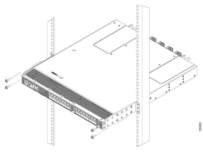
The rack-mount kit enables you to install the switch into racks of varying depths. You can use the rack-mount kit parts to position the switch with easy access to either the port connections end of the chassis or the end of the chassis with the fan and power supply modules. For instructions on how to install the rack-mount kit, see the Installing the Switch section.

Cisco MDS 9000 Series Telco and EIA Shelf Bracket

The optional Telco and EIA Shelf Bracket Kit (part number DS-SHELF=) can temporarily or permanently support the Cisco MDS 9132T switch during installation. After the front rack-mount brackets are securely attached to the rack-mounting rails, the shelf bracket can be removed.

The Telco and EIA Shelf Bracket kit supports the following configurations:

  • A Cisco MDS 9132T Switch in a two-post Telco rack

  • A Cisco MDS 9132T Switch in a four-post EIA rack


Note


Telco and EIA Shelf Bracket optional kit is not provided with the switch; to order the kit, contact your switch supplier.


This section describes the procedure for installing a Cisco MDS 9132T switch in a rack or cabinet using the optional Telco and EIA Shelf Bracket Kit.

Shelf-Installation Guidelines


Caution


  • If the rack is on wheels, ensure that the brakes are engaged or the rack is otherwise stabilized.

  • If you are installing this kit in an EIA rack, attach the shelf to all four rack-mounting posts; the EIA posts may not be thick enough to prevent flexing of shelf brackets if only two posts are used.


Before Installing the Shelf Brackets

Before installing the shelf brackets, inspect the contents of your kit. The following table lists the contents of the shelf bracket kit:

Quantity

Part Description

2

Slider brackets

2

Shelf brackets

1

Crossbar

2

10-32 x 3/8-in. Phillips pan-head screws

16

12-24 x 3/4-in. Phillips screws

16

10-24 x 3/4-in. Phillips screws

Required Equipment

You need the following equipment for this installation:

  • Number 2 Phillips screwdriver

  • Tape measure and level (to ensure that shelf brackets are at level with each other)

  • NEBS plate - If the airflow is port-side intake

Installing the Shelf Bracket Kit into a Two-Post Telco Rack

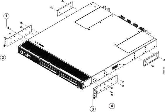
The following figure shows the installation of the shelf bracket kit into a two-post Telco rack:
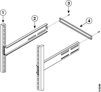
Figure 1. Installing the Shelf Bracket Kit into a Telco Rack


1

Rack-mounting post

3

10-32 screws

2

Shelf bracket

4

Crossbar

To install the shelf brackets in a Telco rack, follow these steps:

Procedure

Step 1

Position a shelf bracket inside a rack-mounting post as shown in Installing the Shelf Bracket Kit into a Telco Rack and align the screw holes at the front of the shelf bracket with the holes in the rack-mounting post. Then, attach the shelf bracket to the rack-mounting post using a minimum of four 12-24 or 10-24 screws.

Note


The bottom hole of the shelf bracket should align with the bottom hole (the hole immediately above the 1/2 in. spacing) of a rack unit on the rack-mounting post.

Step 2

Repeat Step 1 with the other shelf brackets.

Step 3

Verify that the shelf brackets are at the same height (using the level or tape measure, as desired).

Step 4

Attach the crossbar to the rear of the shelf brackets, as shown in Installing the Shelf Bracket Kit into a Telco Rack, using the 10-32 screws.


Installing the Shelf Bracket Kit into a Four-Post EIA Rack

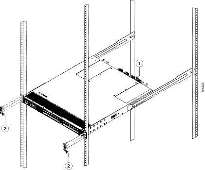
The following figure shows the installation of the shelf bracket kit into a four-post EIA rack:
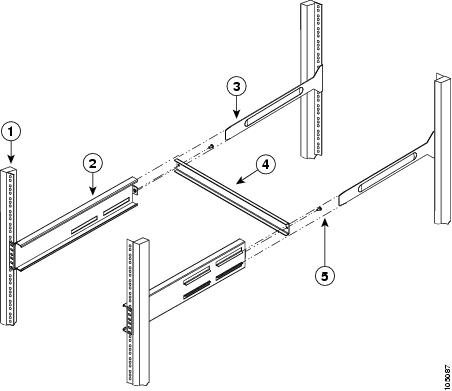
Figure 2. Installing the Shelf Bracket Kit into an EIA Rack


1

Rack-mounting post

4

Crossbar

2

Shelf bracket

5

10-32 screws

3

Slider post

To install the shelf brackets in an EIA rack, follow these steps:

Procedure

Step 1

Position a shelf bracket inside the rack-mounting posts, as shown in Installing the Shelf Bracket Kit into an EIA Rack. Align the screw holes at the front of the shelf bracket with the holes in the front rack-mounting post. Then, attach the shelf bracket to the front rack-mounting post using a minimum of four 12-24 or 10-24 screws.

Note


The bottom hole of the shelf bracket should align with the bottom hole (the hole immediately above the 1/2 in. spacing) of a rack unit on the rack-mounting post.

Step 2

Repeat Step 1 with the other shelf brackets.

Step 3

Verify that the shelf brackets are at the same height (using the level or tape measure, as desired).

Step 4

Attach the crossbar to the shelf brackets, as shown in Installing the Shelf Bracket Kit into an EIA Rack, using the 10-32 screws.

Step 5

Insert the slider posts into the shelf brackets, as shown in Installing the Shelf Bracket Kit into an EIA Rack. Attach them to the rear rack-mounting posts, using a minimum of four 12-24 or 10-24 screws.


Preinstallation Guidelines

Airflow Considerations

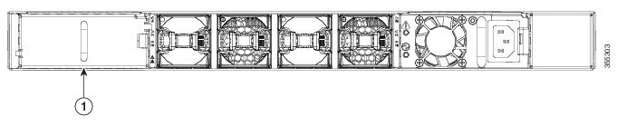
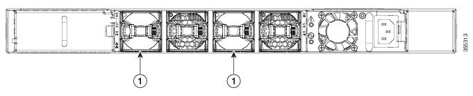
The switch comes with fan modules and power supply units that have either port-side intake or port-side exhaust airflow for cooling the switch. If you are positioning the port end of the switch in a cold aisle, make sure that the switch has a port-side intake fan and power supply modules with red colorings. If you are positioning the port end of the switch in a cold aisle, make sure that the switch has a port-side exhaust fan and power supply modules with blue colorings. If you are positioning the fan and power supply modules in a cold aisle, make sure that the switch has port-side bidrectional fan and power supply modules with white colorings. All fan modules and power-supply modules must have the same direction of airflow.

Connection Guidelines for AC-Powered Systems

To connect to the Cisco MDS 9132T switch AC power supplies to the site power source, follow these guidelines:

  • Each power supply should have its own dedicated branch circuit.

  • Circuits should be sized according to local and national codes.

  • The AC power receptacles that are used to plug in the chassis must be the grounding type. The grounding conductors that connect to the receptacles should connect to protective earth ground in the service equipment.

Installation Guidelines

Follow these guidelines when installing the Cisco MDS 9132T switch:

  • Plan your site configuration and prepare the site before installing the switch. The recommended site planning tasks are listed in the Site Planning and Maintenance Records section.

  • Ensure that there is adequate space around the switch to allow for servicing the switch and for adequate airflow. The airflow requirements are listed the Technical Specifications section.

  • Ensure that you are positioning the switch in a rack so that it takes in cold air from the cold aisle and sends out air to the hot aisle. For more informatiom, see the Airflow Considerations section.

  • Ensure that the air-conditioning meets the heat-dissipation requirements listed in the Technical Specifications section.

  • Ensure that the cabinet or rack meets the requirements listed in the Cabinet and Rack Installation section.

  • Ensure that the chassis is adequately grounded. If the switch is not mounted on a grounded rack, we recommend that you connect both the system ground on the chassis and the site power ground to an earth ground.

  • Ensure that the site power meets the power requirements listed in the Technical Specifications section. If available, you can use an uninterruptible power supply (UPS) to protect against power failures.


    Caution


    Avoid UPS types that use ferro-resonant technology. These UPS types can become unstable with systems such as the Cisco MDS 9000 Series, which can in turn have substantial current draw fluctuations because of fluctuating data traffic patterns.


  • Ensure that circuits are sized according to local and national codes.

    For North America, the 650-W power supplies require a 15-A circuit. If you are using a 200 or 240 VAC power source in North America, the circuit must be protected by a two-pole circuit breaker.


    Caution


    To prevent loss of input power, ensure that the total maximum loads on the circuits supplying power to the switch are within current ratings for wiring and breakers.


Unpacking and Inspecting the Switch


Caution


When handling switch components, wear an ESD strap and handle modules using only the carrier edges. An ESD socket is provided on the chassis. For an ESD socket to be effective, the chassis must be grounded through the power cable, the chassis ground, or the metal-to-metal connection with a grounded rack.


Tip


Retain the shipping container in case the chassis has to be shipped in the future.


Note


The switch is thoroughly inspected before shipment. If any damage occurs during transportation, or if any item is missing, contact your customer representative immediately. If you purchased Cisco support through a Cisco reseller, contact the reseller directly. If you purchased support directly from Cisco, contact Cisco Technical Support.


To inspect the shipment, follow these steps:

  1. Compare the shipment to the equipment list provided by your customer service representative and verify that you have received all items, including the following:

    • Grounding lug kit

    • Rack-mount kit

    • ESD wrist strap

    • Cables and connectors

    • Optional items, if any, ordered

  2. Check for damage and report any discrepancies or damage, to your customer service representative. Have the following information ready:

    • Invoice number of shipper (see packing slip)

    • Model and serial number of the damaged unit

    • Description of damage

    • Effect of damage on the installation

  3. Check to be sure that all the power supplies and the fan trays have the expected direction of airflow. Port-side intake airflow modules have a red coloring, and port-side exhaust airflow modules have blue coloring. For more information, see the Power Supplies and Fan Modules sections.

Installing the Switch

This section describes how to use the rack-mount kit to install the Cisco MDS 9132T switch into a cabinet or rack that meets the requirements described in the Cabinet and Rack Requirements section.

Installing the Switch on Shelf Brackets

This section provides general instructions for installing the switch on top of the shelf brackets. Note that this is an optional task.


Note


Before you install, operate, or service the system, refer to Regulatory Compliance and Safety Information for the Cisco MDS 9000 Family for important safety information.


To install the switch on top of the shelf brackets, follow these steps:

Procedure


Step 1

Verify that the shelf brackets are level and securely attached to the rack-mounting posts, the crossbar is securely attached to the shelf brackets, and the rack is stabilized.

Step 2

Slide the switch onto the shelf brackets, ensuring that it is squarely positioned.

Step 3

Attach the switch to the rack-mounting posts.

Caution


We recommend that you ground the chassis even if the rack is already grounded. A grounding pad with two threaded M4 holes is provided on the chassis for attaching a grounding lug.

Note


For switches installing in the USA, the grounding lug must be NRTL listed and compatible with copper conductors. Only copper conductors (wires) must be used and these conductors must comply with National Electrical Code (NEC) for ampacity.


NEBS Compliance

In case of port-side intake airflow, the chassis has to be NEBS compliant. To be NEBS compliant, install the NEBS kit by following these steps:

  1. Install two NEBS rack–mount brackets onto the switch.

  2. Install the NEBS air-baffle onto the switch, and ensure that the direction is as shown in the following images.

Figure 3. NEBS Kit for 2-post installation
Figure 4. NEBS Kit for 4-post installation

1.

NEBS air-baffle

For more information on how to install the switch, see the Installing the Switch in a 4-post Rack and Installing the Switch in a 2-post Rack.

Installing the Switch in a 4-Post Rack

To install the switch, you must attach the front and rear mounting brackets to the switch, install the slider rails on the rear of the rack, slide the switch into the slider rails, and secure the switch to the front of the rack. Typically, the front of the rack is the side that is easiest to access for maintenance.

Before you begin

  • Inspect the switch shipment to ensure that you have everything you ordered.

  • Make sure that the switch rack-mount kit includes the following parts:

    • Front rack-mount brackets (2)

    • Rear rack-mount brackets (2)

    • Slider rails (2)

    • M4 x 0.7 x 8-mm Phillips countersink screws (12)

  • The rack is installed and secured to its location.

Procedure


Step 1

Install two front-mount brackets to the switch as follows:

  1. Determine which end of the chassis is to be located in the cold aisle as follows:

    • If the switch has port-side intake modules (fan modules with red coloring), position the switch so that its ports are in the cold aisle.

    • If the switch has port-side exhaust modules (fan modules with blue coloring), position the switch so that its fan and power-supply modules are in the cold aisle.

  2. Position a front-mount bracket so that four of its screw holes are aligned to the screw holes on the side of the chassis.

    Note


    You can align any four of the holes in the front rack-mount bracket to four of the six screw holes on the side of the chassis. The holes that you use depend on the requirements of your rack and the amount of clearance required for interface cables (3 in. [76 mm] minimum) and module handles (1 in. [25 mm] minimum).

    1 & 4. Four M4 screws

    2 & 3. Front rack-mount bracket

  3. Secure the front-mount bracket to the chassis using the four M4 screws and tighten each screw to 12 in-lb (1.36 N·m) of torque.

  4. Repeat Step 1 for the other front rack-mount bracket on the other side of the switch, and be sure to position that bracket the same distance from the front of the switch.

Step 2

Install the two rear rack-mount brackets on the chassis, as follows:

  1. Align the two screw holes on a rear rack-mount bracket to the middle two screw holes in the remaining six screw holes on a side of the chassis if you are aligning the guide to holes that are near the port connections end of the chassis.

  2. Attach the guide to the chassis using two M4 screws. Tighten the screws to 12 in-lb (1.36 N·m) of torque.

  3. Repeat Step 2 for the other rear rack-mount bracket on the other side of the switch.

Step 3

If you are not installing the chassis into a grounded rack, you must attach a customer-supplied grounding wire to the chassis, as explained in Grounding the Switch. However, if you are installing the chassis into a grounded rack, you can skip this step.

Step 4

Install the slider rails into the rack or cabinet, as follows:

  1. Determine which two posts of the rack or cabinet you should use for the slider rails. Of the four vertical posts in the rack or cabinet, two will be used for the front-mount brackets attached to the easiest-accessed end of the chassis, and the other two posts will have the slider rails.

  2. Position a slider rail at the desired level on the back side of the rack and use two 12-24 screws or two 10-32 screws, depending on the rack thread type, to attach the posts to the rack. Tighten the 12-24 screws to 30 in-lb (3.39 N·m) of torque, and tighten the 10-32 screws to 20 in-lb (2.26 N·m) of torque.

  3. Repeat Step 3 to attach the other slider rail to the other side of the rack.

    To make sure that the slider rails are at the same level, you should use a level tool or tape measure, or carefully count the screw holes in the vertical mounting posts.

Step 5

Insert the switch into the rack and attach it as follows:

1. Fan-tray end of the chassis.

2. Customer-supplied rack-mount screw.

  1. Holding the switch with both hands, position the two rear rack-mount brackets on the switch between the rack or cabinet posts that do not have slider rails attached to them.

  2. Align the two rear rack-mount guides on either side of the switch with the slider rails installed in the rack. Slide the rack-mount guides onto the slider rails, and then gently slide the switch all the way into the rack until the front rack-mount brackets come in contact with two rack or cabinet posts.

    Note


    If you attached a grounding cable to the chassis, you will need to bend one of the rack-mount posts slightly to allow the grounding lug to go behind the post.

  3. Holding the chassis level, insert two screws (12-24 or 10-32, depending on the rack type) into each of the two front rack-mount brackets (using a total of four screws), and into the cage nuts or threaded holes in the vertical rack-mounting posts.

  4. Tighten the 10-32 screws to 20 in-lb (2.26 N·m), or tighten the 12-24 screws to 30 in-lb (3.39 N·m).

Step 6

If you have attached a grounding wire to the chassis grounding pad, connect the other end of the wire to the facility ground.


Installing the Switch into a 2-Post Rack

Procedure


Step 1

Install two rack–mount brackets onto the switch as follows:

  1. Determine which end of the chassis is to be located in the cold aisle as follows:

    • If the switch has port-side intake modules (fan modules with red coloring), position the switch so that its ports is in the cold aisle.

    • If the switch has port-side exhaust modules (fan modules with blue coloring), position the switch so that its fan and power supply modules is in the cold aisle.

  2. Position a rack–mount bracket so that four of its screw holes are aligned to the screw holes on the side of the chassis. Then, secure the front-mount bracket to the chassis using four M4 screws.

    Note

     
    You can align four of the holes in the front rack-mount bracket to four of the screw holes on the front side of chassis or four of the screw holes on the rear side of the chassis. The holes that you use depend on which side of your chassis needs to be put in the cold aisle.
    Figure 5. Installing Rack-mount Brackets on the Front Side of the Chassis


    Figure 6. Installing Rack-mount Brackets on the Rear Side of the Chassis
  3. Repeat Step 1b, for the other front rack-mount bracket on the other side of the switch and be sure to position that bracket the same distance from the front of the switch.

Step 2

Install the switch onto the 2-post rack:

  1. Holding the switch with both hands, position the back of the switch between the two posts of the rack. Then gently move the switch until the front rack-mount brackets come in contact with two rack posts.

  2. Holding the chassis level, insert two screws (12-24 or 10-32, depending on the rack type) into each of the two front rack-mount brackets (using a total of four screws) and into the cage nuts or threaded holes in the vertical rack-mounting posts.

    Figure 7. Installing the Switch onto the 2-post Rack


  3. Tighten the 10-32 screws to 20 in-lb (2.26 N.m) or tighten the 12-24 screws to 30 in-lb (3.39 N.m).


Removing the Shelf Bracket Kit (Optional)

The shelf bracket kit can be removed after the Cisco MDS 9132T switch has been installed in a four-post EIA rack, and the front rack-mount brackets and the C brackets are securely attached to the rack-mounting posts.

To remove the shelf bracket kit, follow these steps:

Procedure


Step 1

Remove the screws fastening the slider brackets to the rear rack-mounting posts, and then slide the slider brackets out of the shelf brackets.

Step 2

Remove the screws fastening the crossbar to the shelf brackets, and then remove the crossbar.

Step 3

Remove the screws fastening the shelf brackets to the front rack-mounting posts and remove the shelf brackets from the rack.


Grounding the Switch

The switch chassis is automatically grounded when you install the switch properly in a grounded rack with metal-to-metal connections between the switch and rack.

Alternatively, you can ground the chassis (this is required if the rack is not grounded) by attaching a customer-supplied grounding cable to the chassis grounding pad and the facility ground.


Warning


This equipment must be grounded. Never defeat the ground conductor or operate the equipment in the absence of a suitably installed ground conductor. Contact the appropriate electrical inspection authority or an electrician if you are uncertain that suitable grounding is available. Statement 1024


Warning


When installing or replacing the unit, the ground connection must always be made first and disconnected last. Statement 1046


To connect the switch chassis to the facility ground, you need the following tools and materials:

  • Grounding lug—A two-holed standard barrel lug that supports up to 6 AWG wire. This lug is supplied with the accessory kit.

  • Grounding screws—Two M4 x 8 mm (metric) pan-head screws. These screws are shipped with the accessory kit.

  • Grounding wire—Not supplied with the accessory kit. This wire should be sized to meet local and national installation requirements. Depending on the power supply and system, a 12 AWG to 6 AWG copper conductor is required for the USA installations. We recommend that you use commercially available 6 AWG wire. The length of the grounding wire depends on the proximity of the switch to proper grounding facilities.

  • Number 1 manual Phillips-head torque screwdriver.

  • Crimping tool to crimp the grounding wire to the grounding lug.

  • Wire stripping tool to remove the insulation from the grounding wire.

Procedure


Step 1

Use a wire stripping tool to remove approximately 0.75 in. (19 mm) of the covering from the end of the grounding wire.

Step 2

Insert the stripped end of the grounding wire into the open end of the grounding lug, and use a crimping tool to crimp the lug to the wire. Verify that the ground wire is securely attached to the grounding lug by attempting to pull the wire out of the crimped lug.

Step 3

Secure the grounding lug to the chassis grounding pad with two M4 screws, and tighten each screw to 11.5 to 15 in-lb (1.3 to 1.7 N·m) of torque.

Step 4

Prepare the other end of the grounding wire and connect it to an appropriate grounding point in your site to ensure an adequate earth ground for the switch. If the rack is fully bonded and grounded, connect the grounding wire, as explained in the documentation provided by the vendor from whom you bought the rack.


Installing and Removing Components


Warning


Hazardous voltage or energy is present on the backplane when the system is operating. Use caution when servicing. Statement 1034


Caution


During this procedure, wear grounding wrist straps to avoid ESD damage to the switch.


Installing and Removing the Linecard Expansion Module

This section provides instructions for installing and removing the Linecard Expansion Module.

Installing the Linecard Expansion Module

To install a Linecard Expansion Module, follow the steps provided in this section:

Before you begin

If the LEM blank module is installed, remove it as follows:

1. Unscrew the locking screw.

2. Gently pull the linecard expansion module ejector till the linecard expansion blank module is slightly ejected.

3. Remove the linecard expansion blank module.

Procedure

Step 1

Power off the switch.

Step 2

Gently pull the LEM ejector so as to insert the LEM.

Step 3

Gently slide the LEM into the LEM bay till it clicks into place with the help of the Linecard Expansion Module ejector.

Step 4

Secure the Linecard Expansion Module ejector with the locking screw.


Removing the Linecard Expansion Module

To remove a Linecard Expansion Module, follow these steps:

Procedure

Step 1

Power off the switch.

Step 2

Unscrew the locking screw.

Step 3

Gently pull the LEM ejector till the LEM is slightly ejected.

Step 4

Remove the LEM.

Step 5

Physically insert the linecard expansion blank module to ensure proper system cooling.


Installing and Removing Power Supplies

This section provides instructions for installing and removing the power supplies in the Cisco MDS 9132T Switch.

Installing Power Supplies

You can replace one power supply while the other one provides power to the switch.

Before you begin

If the PSU blank module is inserted, remove it as follows:

1. Unscrew the locking screw.

2. Gently pull the power supply blank module out of the bay.

Figure 8. Inserted Power Supply Blank Module

1

Power supply blank module

  • To implement n+n redundancy, there must be two external power sources and two PSUs attached to each power source. Otherwise, only one power source is required.

  • There must be an earth ground connection to the chassis to which you are installing the replacement module. Typically, the chassis is grounded by its metal-to-metal connection with a grounded rack. If you need to ground the chassis, see Grounding the Switch.

Procedure

Step 1

Holding the power supply unit with one hand underneath it and the other hand holding the handle, turn the power supply so that its release latch is on the right side, and align the back end of the power supply (the end with the electrical connections) to the open power supply slot. Carefully slide the power supply unit all the way into the slot until it clicks into place.

Note


If the power supply unit does not fit into the slot opening, turn the unit over and try again.

Step 2

Test the installation by trying to pull the power supply out of the slot without using the release latch.

If the power supply does not move out of place, it is secured in the slot. If the power supply moves, carefully press it all the way into the slot until it clicks in place and tighten the locking screw.

Step 3

Attach the power cable to the electrical outlet on the front of the power supply.

Step 4

Make sure that the other end of the power cable is attached to the appropriate power source for the power supply. If the power source has a switch, slide it to the On position.

Note


Depending on the outlet receptacle on your power distribution unit, you might need the optional jumper cable to connect the switch to your outlet receptacle.

Step 5

Verify that the power supply is operational by making sure that the power supply LED is green. For information on what the power supply LEDs indicate, see the Switch LEDs section.


Removing Power Supplies

You can remove one faulty power supply, while the other one provides enough power to the switch. Install a new power supply or a power supply blank module in the open slot.

Procedure

Step 1

Holding the plug for the power cable, pull the plug out from the power receptacle on the power supply, and verify that both the power supply LEDs are off.

Step 2

Grasp the power supply handle while pressing the release latch towards the power supply handle.

Step 3

Place your other hand under the power supply to support it while you slide it out of the chassis.

Caution


Do not touch the electrical connectors on the back side of the module and prevent anything else from coming into contact with and damaging the connectors.

Step 4

Insert a power supply blank module, as shown in Power Supply Blank Module if you do not have a new power supply unit.


Installing and Removing Fan Modules

This section provides instructions for installing and removing the fan modules for the Cisco MDS 9132T switch.

You can replace one of the four fan modules even when the switch is operating so long as you perform the replacement within one minute of removing the old fan module. If you cannot perform the replacement within one minute, leave the original fan module in the chassis to maintain the designed airflow until you have the replacement fan module on hand and can perform the replacement.


Caution


If you are replacing a module during operations, be sure that the replacement fan module has the correct direction of airflow, which means that it has the same airflow direction as the other modules in the chassis. Also, be sure that the airflow direction takes in air from a cold aisle and sends it out to a hot aisle. Otherwise, the switch can overheat and shut down.

If you are changing the airflow direction of all the modules in the chassis, you must shut down the switch before replacing all the fan and power supply modules with modules using the other airflow direction. During operations, all the modules must have the same direction of airflow.


Installing a Fan Module

To install a new fan module, follow these steps:

Before you begin

If a fan blank module is installed, remove it as follows:

  • Press the two sides of the fan blank module handle and pull on the handles enough to unseat it from its connectors.

  • Holding the handle, pull the module out of the chassis.

Figure 9. Inserted Fan Blank Modules

1

Fan blank modules

  • A fan slot must be open and ready for the new fan module to be installed.

  • You must have a new fan module on hand and ready to install within one minute of removing the original fan module if the switch is operating.

  • The new fan module must have the same airflow direction as the other fan and power supply modules installed in the switch. All of these modules must have either red coloring (port-side intake airflow) or they must all have blue coloring (port-side exhaust airflow).

Procedure

Step 1

Holding the fan module by its handle, align the back of the fan module (the side with the electrical connectors) to the open fan slot in the chassis.

Step 2

Slide the fan module into the fan module bay until it clicks into place and tighten the locking screw.

Step 3

Verify that the Status LED turns on and becomes green.


Removing a Fan Module

The fan module is designed to be removed and replaced while the system is operating without presenting an electrical hazard or damaging the system.


Caution


The Cisco MDS 9000 Series Switches have internal temperature sensors that can shut down the system if the temperature within the chassis exceed certain safety thresholds. To accurately monitor the system temperature, the temperature sensors require sufficient airflow through the chassis. In the event that a fan module is removed from the chassis and the airflow is reduced, the system will bypass the temperature sensor information and shut down after five minutes to prevent undetected overheating. However, the switches will shut down sooner if the major temperature threshold is exceeded.


Warning


While removing the fan module, keep your hands and fingers away from the spinning fan blades. Let the fan blades completely stop before you remove the fan module. Statement 258


To remove an existing fan module, follow these steps:

Procedure

Step 1

On the fan module that you are removing, press the two sides of the fan module handle next to where it connects to the fan module and pull on the handles enough to unseat it from its connectors.

Step 2

Holding the handle, pull the module out of the chassis.

Caution


Do not touch the electrical connectors on the back side of the module and prevent anything else from coming into contact with and damaging the connectors.

Step 3

Insert a fan blank module, as shown in Inserted Fan Blank Modules if you do not have a new fan module.