
Cables and Adapters
The Cisco MDS 9132T Switch accessory kit includes the following:
-
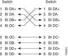
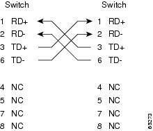
RJ-45-to-RJ-45 rollover cable
-
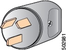
RJ-45-to-DB-9 female DTE adapter (labeled Terminal)
-
RJ-45-to-DB-25 female DTE adapter (labeled Terminal)
-
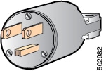
RJ-45-to-DB-25 male DCE adapter (labeled Modem)
 Note |
Additional cables and adapters can be ordered from your customer service representative. |
Note |
If you purchased this product through a Cisco reseller, contact the reseller directly for technical support. If you purchased this product directly from Cisco, contact Cisco Technical Support at http://www.cisco.com/c/en/us/support/index.html. |

 Feedback