Port-channels are
logical interfaces in NX-OS used to aggregate bandwidth for multiple physical
ports and also for providing redundancy in case of link failures. In NX-OS,
port-channel interfaces are identified by user-specified numbers in the range 1
to 4096 unique within a node. Port-channel interfaces are either configured
explicitly (using interface port-channel command) or created implicitly (using
channel-group command). The configuration of the port-channel interface is
applied to all the member ports of the port-channel. There are certain
compatibility parameters (speed, for example) that cannot be configured on the
member ports.
In the ACI model,
port-channels are configured as logical entities identified by a name to
represent a collection of policies that can be assigned to set of ports in one
or more leaf nodes. Such assignment creates one port-channel interface in each
of the leaf nodes identified by an auto-generated number in the range 1 to 4096
within the leaf node, which may be same or different among the nodes for the
same port-channel name. The membership of these port-channels may be same or
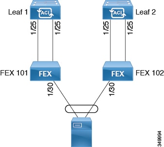
different as well. When port-channel is created on the FEX ports, the same
port-channel name can be used to create one port-channel interface in each of
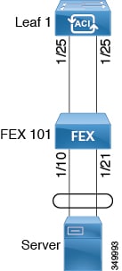
the FEX attached to the leaf node. Thus, it is possible to create up to N+1
unique port-channel interfaces (identified by the auto-generated port-channel
numbers) for each leaf node attached to N FEX modules. This is illustrated with
the examples below. Port-channels on the FEX ports are identified by specifying
the
fex-id
along
with the port-channel name (
interface port-channel foo
fex 101
, for example).
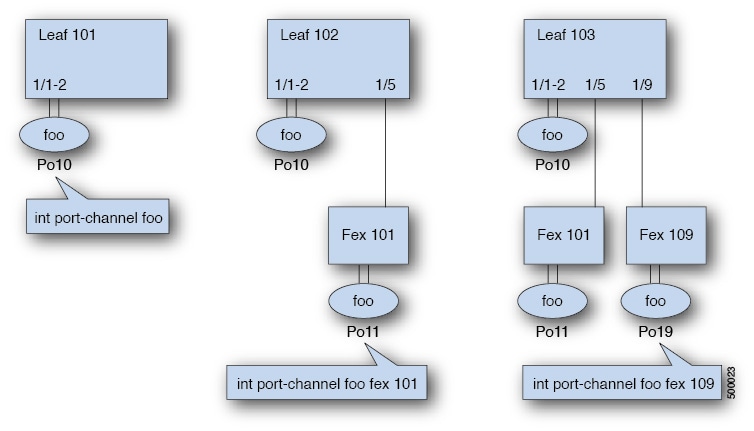
-
N+1
instances per leaf of port-channel foo are possible when each leaf is connected
to N FEX nodes.
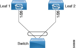
-
Leaf ports
and FEX ports cannot be part of the same port-channel instance.
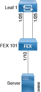
-
Each FEX
node can have only one instance of port-channel foo.
Examples
Configure a port
channel (global configuration). A logical entity foo is created that represents
a collection of policies with two configurations: speed and channel mode. More
properties can be configured as required.

Note |
The channel
mode command is equivalent to the mode option in the channel group command in
NX-OS. In ACI, however, this supported for the port-channel (not on member
port).
|
apic1(config)# template port-channel foo
apic1(config-po-ch-if)# switchport access vlan 4 tenant ExampleCorp application Web epg webEpg
apic1(config-po-ch-if)# speed 10G
apic1(config-po-ch-if)# channel-mode active
Configure ports to
a port-channel in a FEX. In this example, port channel foo is assigned to ports
Ethernet 1/1-2 in FEX 101 attached to leaf node 102 to create an instance of
port channel foo. The leaf node will auto-generate a number, say 1002 to
identify the port channel in the switch. This port channel number would be
unique to the leaf node 102 regardless of how many instance of port channel foo
are created.
Note |
The
configuration to attach the FEX module to the leaf node must be done before
creating port channels using FEX ports.
|
apic1(config)# leaf 102
apic1(config-leaf)# interface ethernet 101/1/1-2
apic1(config-leaf-if)# channel-group foo
In Leaf 102, this
port channel interface can be referred to as interface port-channel foo FEX
101.
apic1(config)# leaf 102
apic1(config-leaf)# interface port-channel foo fex 101
apic1(config-leaf)# shut
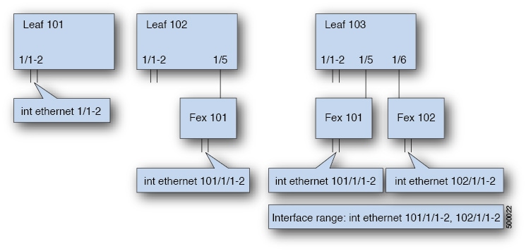
Configure ports
to a port channel in multiple leaf nodes. In this example, port channel foo is
assigned to ports Ethernet 1/1-2 in each of the leaf nodes 101-103. The leaf
nodes will auto generate a number unique in each node (which may be same or
different among nodes) to represent the port-channel interfaces.
apic1(config)# leaf 101-103
apic1(config-leaf)# interface ethernet 1/1-2
apic1(config-leaf-if)# channel-group foo
Add members to
port channels. This example would add two members eth1/3-4 to the port-channel
in each leaf node, so that port-channel foo in each node would have members eth
1/1-4.
apic1(config)# leaf 101-103
apic1(config-leaf)# interface ethernet 1/3-4
apic1(config-leaf-if)# channel-group foo
Remove members
from port channels. This example would remove two members eth1/2, eth1/4 from
the port channel foo in each leaf node, so that port channel foo in each node
would have members eth 1/1, eth1/3.
apic1(config)# leaf 101-103
apic1(config-leaf)# interface eth 1/2,1/4
apic1(config-leaf-if)# no channel-group foo
Configure
port-channel with different members in multiple leaf nodes. This example shows
how to use the same port-channel foo policies to create a port-channel
interface in multiple leaf nodes with different member ports in each leaf. The
port-channel numbers in the leaf nodes may be same or different for the same
port-channel foo. In the CLI, however, the configuration will be referred as
interface port-channel foo. If the port-channel is configured for the FEX
ports, it would be referred to as interface port-channel foo fex
<fex-id>.
apic1(config)# leaf 101
apic1(config-leaf)# interface ethernet 1/1-2
apic1(config-leaf-if)# channel-group foo
apic1(config-leaf-if)# exit
apic1(config-leaf)# exit
apic1(config)# leaf 102
apic1(config-leaf)# interface ethernet 1/3-4
apic1(config-leaf-if)# channel-group foo
apic1(config-leaf-if)# exit
apic1(config-leaf)# exit
apic1(config)# leaf 103
apic1(config-leaf)# interface ethernet 1/5-8
apic1(config-leaf-if)# channel-group foo
apic1(config-leaf-if)# exit
apic1(config-leaf)# interface ethernet 101/1/1-2
apic1(config-leaf-if)# channel-group foo
Configure per
port properties for LACP. This example shows how to configure member ports of a
port-channel for per-port properties for LACP.
Note |
In ACI model,
these commands are allowed only after the ports are member of a port channel.
If a port is removed from a port channel, configuration of these per-port
properties would be removed as well.
|
apic1(config)# leaf 101
apic1(config-leaf)# interface ethernet 1/1-2
apic1(config-leaf-if)# channel-group foo
apic1(config-leaf-if)# lacp port-priority 1000
apic1(config-leaf-if)# lacp rate fast
Configure admin
state for port channels. In this example, a port-channel foo is configured in
each of the leaf nodes 101-103 using the channel-group command. The admin state
of port-channel(s) can be configured in each leaf using the port-channel
interface. In ACI model, the admin state of the port-channel cannot be
configured in the global scope.
// create port-channel foo in each leaf
apic1(config)# leaf 101-103
apic1(config-leaf)# interface ethernet 1/3-4
apic1(config-leaf-if)# channel-group foo
// configure admin state in specific leaf
apic1(config)# leaf 101
apic1(config-leaf)# interface port-channel foo
apic1(config-leaf-if)# shut
Override config is
very helpful to assign specific vlan-domain, for example, to the port-channel
interfaces in each leaf while sharing other properties.
// configure a port channel global config
apic1(config)# interface port-channel foo
apic1(config-if)# speed 1G
apic1(config-if)# channel-mode active
// create port-channel foo in each leaf
apic1(config)# leaf 101-103
apic1(config-leaf)# interface ethernet 1/1-2
apic1(config-leaf-if)# channel-group foo
// override port-channel foo in leaf 102
apic1(config)# leaf 102
apic1(config-leaf)# interface port-channel foo
apic1(config-leaf-if)# speed 10G
apic1(config-leaf-if)# channel-mode on
apic1(config-leaf-if)# vlan-domain dom-foo
This example shows
how to change port channel assignment for ports using the channel-group
command. There is no need to remove port channel membership before assigning to
other port channel.
apic1(config)# leaf 101-103
apic1(config-leaf)# interface ethernet 1/3-4
apic1(config-leaf-if)# channel-group foo
apic1(config-leaf-if)# channel-group bar
 Feedback