Access Interfaces

Physical Ports

Configuring Leaf Switch Physical Ports Using Policy Association

The procedure below uses a Quick Start wizard.


Note


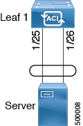
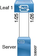
This procedure provides the steps for attaching a server to an ACI leaf switch interface. The steps would be the same for attaching other kinds of devices to an ACI leaf switch interface.
Figure 1. Switch Interface Configuration for Bare Metal Server


Before you begin

  • The ACI fabric is installed, APIC controllers are online, and the APIC cluster is formed and healthy.

  • An APIC fabric administrator account is available that will enable creating the necessary fabric infrastructure configurations.

  • The target leaf switches are registered in the ACI fabric and available.

Procedure


Step 1

On the APIC menu bar, navigate to Fabric > External Access Policies > Quick Start, and click Configure an interface, PC, and VPC.

Step 2

In the Select Switches To Configure Interfaces work area, click the large + to select switches to configure. In the Switches section, click the + to add switch ID(s) from the drop-down list of available switch IDs and click Update.

Step 3

Click the large + to configure switch interfaces.

The interface policy group is a named policy that specifies the group of interface policies you will apply to the selected interfaces of the switch. Examples of interface policies include Link Level Policy (for example, 1gbit port speed), Storm Control Interface Policy, and so forth.

Note


The Attached Device Type domain is required for enabling an EPG to use the interfaces specified in the switch profile.

  1. Specify individual as the interface type to use.

  2. Specify the interface ID to use.

  3. Specify the interface policies to use.

  4. Specify the attached device type to use. Choose Bare Metal for connecting bare metal servers. Bare metal uses the phys domain type.

  5. Click Save to update the policy details, then click Submit to submit the switch profile to the APIC.

    The APIC creates the switch profile, along with the interface, selector, and attached device type policies.

Verification: Use the CLI show int command on the switch where the server is attached to verify that the switch interface is configured accordingly.


What to do next

This completes the basic leaf interface configuration steps.

Note


While this configuration enables hardware connectivity, no data traffic can flow without a valid application profile, EPG, and contract that is associated with this hardware configuration.


Configuring Leaf Switch Physical Ports Using Port Association

This procedure provides the steps for attaching a server to an ACI leaf switch interface. The steps would be the same for attaching other kinds of devices to an ACI leaf switch interface.

Before you begin

  • The ACI fabric is installed, APIC controllers are online, and the APIC cluster is formed and healthy.

  • An APIC fabric administrator account is available that will enable creating the necessary fabric infrastructure configurations.

  • The target leaf switches are registered in the ACI fabric and available.

Procedure


Step 1

On the APIC menu bar, navigate to Fabric > Inventory > Inventory, choose a pod and navigate to the Configure tab .

A graphical representation of the switch appears. Choose the port to configure. Once selected, port configure type will appear at the top in the form of a highlighted port configuration type. Choose configuraton type and those configuration parameters will appear.

Step 2

Once you have assigned the appropriate fields to the configuration, click Submit.

In this configuration, all changes to the leaf switch are done by selecting the port and applying the policy to it. All leaf switch configuration is done right here on this page.

You have selected the port then applied a policy to it.

What to do next

This completes the basic leaf interface configuration steps.

Configuring Physical Ports in Leaf Nodes and FEX Devices Using the NX-OS CLI

The commands in the following examples create many managed objects in the Cisco Application Centric Infrastructure (ACI) policy model that are fully compatible with the REST API/SDK and GUI. However, the CLI user can focus on the intended network configuration instead of Cisco ACI model internals.

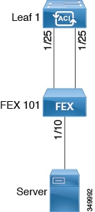
Example of leaf node ports and FEX ports in Cisco ACI shows examples of Ethernet ports directly on leaf nodes or FEX modules attached to leaf nodes and how each is represented in the CLI. For FEX ports, the fex-id is included in the naming of the port itself as in ethernet 101/1/1 . While describing an interface range, the ethernet keyword need not be repeated as in NX-OS. Example: interface ethernet 101/1/1-2, 102/1/1-2 .

Figure 2. Example of leaf node ports and FEX ports in Cisco ACI
  • Leaf node ID numbers are global.

  • The fex-id numbers are local to each leaf node.

  • Note the space after the keyword ethernet .

Procedure


Step 1

configure

Enters global configuration mode.

Example:

apic1# configure

Step 2

leaf node-id

Specifies the leaf nodes to be configured. The node-id can be a single node ID or a range of IDs, in the form node-id1- node-id2 , to which the configuration will be applied.

Example:

apic1(config)# leaf 102

Step 3

interface type

Specifies the interface that you are configuring. You can specify the interface type and identity. For an Ethernet port, use “ethernet slot / port.”

Example:

apic1(config-leaf)# interface ethernet 1/2

Step 4

(Optional) fex associate node-id

If the interface or interfaces to be configured are FEX interfaces, you must use this command to attach the FEX module to a leaf node before configuration.

Note


This step is required before creating a port channel using FEX ports.

Example:

apic1(config-leaf-if)# fex associate 101

Step 5

speed speed

The speed setting is shown as an example. At this point you can configure any of the interface settings shown in the table below.

Example:

apic1(config-leaf-if)# speed 10G

The following table shows the interface settings that can be configured at this point:

Command

Purpose

[no] shut

Shut down physical interface

[no] speed speedValue

Set the speed for physical interface

[no] link debounce time time

Set link debounce

[no] negotiate auto

Configure negotiate

[no] cdp enable

Disable/enable Cisco Discovery Protocol (CDP)

[no] mcp enable

Disable/enable Mis-cabling Protocol (MCP)

[no] lldp transmit

Set the transmit for physical interface

[no] lldp receive

Set the LLDP receive for physical interface

spanning-tree {bpduguard | bpdufilter} {enable | disable}

Configure spanning tree BPDU

[no] storm-control level percentage [ burst-rate percentage ]

Storm-control configuration (percentage)

[no] storm-control pps packets-per-second burst-rate packets-per-second

Storm-control configuration (packets-per-second)

Examples

Configure one port in a leaf node. The following example shows how to configure the interface eth1/2 in leaf 101 for the following properties: speed, cdp, and admin state.

apic1# configure
apic1(config)# leaf 101
apic1(config-leaf)# interface ethernet 1/2
apic1(config-leaf-if)# speed 10G
apic1(config-leaf-if)# cdp enable
apic1(config-leaf-if)# no shut

Configure multiple ports in multiple leaf nodes. The following example shows the configuration of speed for interfaces eth1/1-10 for each of the leaf nodes 101-103.

apic1(config)# leaf 101-103
apic1(config-leaf)# interface eth 1/1-10
apic1(config-leaf-if)# speed 10G

Attach a FEX to a leaf node. The following example shows how to attach a FEX module to a leaf node. Unlike in NX-OS, the leaf node port Eth1/5 is implicitly configured as fabric port and a FEX fabric port channel is created internally with the FEX uplink port(s). In Cisco ACI, the FEX fabric port channels use default configuration and no user configuration is allowed.


Note


This step is required before creating a port channel using FEX ports, as described in the next example.


apic1(config)# leaf 102
apic1(config-leaf)# interface eth 1/5
apic1(config-leaf-if)# fex associate 101

Configure FEX ports attached to leaf nodes. This example shows configuration of speed for interfaces eth1/1-10 in FEX module 101 attached to each of the leaf nodes 102-103. The FEX ID 101 is included in the port identifier. FEX IDs start with 101 and are local to a leaf node.

apic1(config)# leaf 102-103
apic1(config-leaf)# interface eth 101/1/1-10
apic1(config-leaf-if)# speed 1G

Port Cloning

Cloning Port Configurations

In the Cisco APIC Release 3.2 and later, the Port Cloning feature is supported. After you configure a leaf switch port, you can copy the configuration and apply it to other ports. This is only supported in the APIC GUI (not in the NX-OS style CLI).

Port cloning is used for small numbers of leaf switch ports (interfaces) that are individually configured, not for interfaces configured using Fabric Access Policies, that you deploy on multiple nodes in the fabric.

Port cloning is only supported for Layer 2 configurations.

The following policies are not supported on a cloned port:

  • Attachable Access Entity

  • Storm Control

  • DWDM

  • MACsec

Cloning a Configured Leaf Switch Port Using the APIC GUI

This task describes how to clone a leaf switch port that you previously configured. For more information about configuring ports, see Cisco APIC Layer 2 Networking Configuration Guide.

Before you begin

Configure a leaf switch port (with supported Layer 2 policies) in the GUI under Fabric > Inventory, and one of the following:

  • Topology > Interface > Configuration Mode

  • Pod > Interface > Configuration Mode

  • Pod> Leaf > Interface > Configuration Mode

Procedure


Step 1

On the Menu bar, choose Fabric > Inventory.

Step 2

Navigate to the location where you configured the first port.

Step 3

For example, expand Pod and choose Leaf.

Step 4

Click Interface and choose Configuration from the drop-down list under Mode.

Step 5

Click the + icon on the interface menu bar to choose the leaf switch where the port to clone is located.

Step 6

Right-click the port you previously configured and choose Copy.

Step 7

Right-click the port on which you want to copy the configuration and choose Paste.


Port Channels

PC Host Load Balancing Algorithms

The following table provides the configurable port channel hash algorithms used in PC host load balancing across Cisco Application Centric Infrastructure (ACI) leaf node downlinks. This feature was introduced in Cisco Application Policy Infrastructure Controller (APIC), release 2.3(1e).

Table 1. PC Host Load Balancing Algorithms
Traffic Type Hashing Data Points

End Host PC traffic (configurable)

For layer 2 frames: Source MAC address and Destination MAC address

For IP Traffic:

  • Source IP address

  • Destination IP address

  • Layer 4 Source Port

  • Layer 4 Destination Port

When there is more than one port channel on a leaf switch, such as Po1 and Po2, then the following scenario is supported:

  • Po1: Enable symmetric hash with SIP only.

  • Po2: Do not enable symmetric hash. Use default hashing.

However, the following scenario is not supported because the second port channel Po2 has a different hash parameter:

  • Po1: Enable symmetric hash with SIP only.

  • Po2: Enable symmetric hash with DIP only.

That is, on a single leaf switch, all port channels that require symmetric hashing should use the same hash policy/parameter or use the default hashing.


Note


Port channel hash algorithms are applied at each individual leaf node independently. The algorithms do not have influence on load balancing within the fabric, such as load balancing to leaf nodes in a vPC pair. Thus, symmetrical hashing is not supported on a vPC.


ACI Leaf Switch Port Channel Configuration Using the GUI

The procedure below uses a Quick Start wizard.


Note


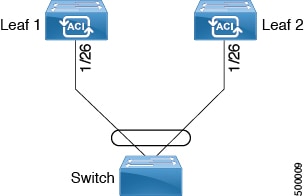
This procedure provides the steps for attaching a server to an ACI leaf switch interface. The steps would be the same for attaching other kinds of devices to an ACI leaf switch interface.
Figure 3. Switch Port Channel Configuration


Before you begin

  • The ACI fabric is installed, APIC controllers are online, and the APIC cluster is formed and healthy.

  • An APIC fabric administrator account is available that will enable creating the necessary fabric infrastructure configurations.

  • The target leaf switches are registered in the ACI fabric and available.

Procedure


Step 1

On the APIC menu bar, navigate to Fabric > External Access Policies > Quick Start, and click Configure an interface, PC, and vPC.

Step 2

In the Select Switches To Configure Interfaces work area, click the large + to select switches to configure. In the Switches section, click the + to add switch ID(s) from the drop-down list of available switch IDs and click Update.

Step 3

Click the large + to configure switch interfaces.

The interface policy group is a named policy that specifies the group of interface policies you will apply to the selected interfaces of the switch. Examples of interface policies include Link Level Policy (for example, 1gbit port speed), Storm Control Interface Policy, and so forth.

Note


The Attached Device Type is required for enabling an EPG to use the interfaces specified in the switch profile.

  1. Specify pc as the interface type to use.

  2. Specify the interface IDs to use.

  3. Specify the interface policies to use. For example, click the Port Channel Policy drop-down arrow to choose an existing port channel policy or to create a new port channel policy.

    Note

     
    • Choosing to create a port channel policy displays the Create Port Channel Policy dialog box where you can specify the policy details and enable features such as symmetric hashing. Also note that choosing the Symmetric hashing option displays the Load Balance Hashing field, which enables you to configure hash tuple. However, only one customized hashing option can be applied on the same leaf switch.

    • Symmetric hashing is not supported on the following switches:

      • Cisco Nexus 93128TX

      • Cisco Nexus 9372PX

      • Cisco Nexus 9372PX-E

      • Cisco Nexus 9372TX

      • Cisco Nexus 9372TX-E

      • Cisco Nexus 9396PX

      • Cisco Nexus 9396TX

  4. Specify the attached device type to use. Choose Bare Metal for connecting bare metal servers. Bare metal uses the phys domain type.

  5. Click Save to update the policy details, then click Submit to submit the switch profile to the APIC.

    The APIC creates the switch profile, along with the interface, selector, and attached device type policies.

Verification: Use the CLI show int command on the switch where the server is attached to verify that the switch interface is configured accordingly.


What to do next

This completes the port channel configuration steps.

Note


While this configuration enables hardware connectivity, no data traffic can flow without a valid application profile, EPG, and contract that is associated with this hardware configuration.


Configuring Port Channels in Leaf Nodes and FEX Devices Using the NX-OS CLI

Port-channels are logical interfaces in NX-OS used to aggregate bandwidth for multiple physical ports and also for providing redundancy in case of link failures. In NX-OS, port-channel interfaces are identified by user-specified numbers in the range 1 to 4096 unique within a node. Port-channel interfaces are either configured explicitly (using the interface port-channel command) or created implicitly (using the channel-group command). The configuration of the port-channel interface is applied to all the member ports of the port-channel. There are certain compatibility parameters (speed, for example) that cannot be configured on the member ports.

In the ACI model, port-channels are configured as logical entities identified by a name to represent a collection of policies that can be assigned to set of ports in one or more leaf nodes. Such assignment creates one port-channel interface in each of the leaf nodes identified by an auto-generated number in the range 1 to 4096 within the leaf node, which may be same or different among the nodes for the same port-channel name. The membership of these port-channels may be same or different as well. When a port-channel is created on the FEX ports, the same port-channel name can be used to create one port-channel interface in each of the FEX devices attached to the leaf node. Thus, it is possible to create up to N+1 unique port-channel interfaces (identified by the auto-generated port-channel numbers) for each leaf node attached to N FEX modules. This is illustrated with the examples below. Port-channels on the FEX ports are identified by specifying the fex-id along with the port-channel name ( interface port-channel foo fex 101 , for example).

  • N+1 instances per leaf of port-channel foo are possible when each leaf is connected to N FEX nodes.

  • Leaf ports and FEX ports cannot be part of the same port-channel instance.

  • Each FEX node can have only one instance of port-channel foo.

Procedure

  Command or Action Purpose

Step 1

configure

Example:

apic1# configure

Enters global configuration mode.

Step 2

template port-channel channel-name

Example:

apic1(config)# template port-channel foo

Creates a new port-channel or configures an existing port-channel (global configuration).

Step 3

[no] switchport access vlan vlan-id tenant tenant-name application application-name epg epg-name

Example:


apic1(config-po-ch-if)# switchport access vlan 4 tenant ExampleCorp application Web epg webEpg

Deploys the EPG with the VLAN on all ports with which the port-channel is associated.

Step 4

channel-mode active

Example:

apic1(config-po-ch-if)# channel-mode active

Note

 
To enable symmetric hashing, enter the lacp symmetric-hash command:
apic1(config-po-ch-if)# lacp symmetric-hash

Note


The channel-mode command is equivalent to the mode option in the channel-group command in NX-OS. In ACI, however, this is supported for the port-channel (not on a member port).

Symmetric hashing is not supported on the following switches:

  • Cisco Nexus 93128TX

  • Cisco Nexus 9372PX

  • Cisco Nexus 9372PX-E

  • Cisco Nexus 9372TX

  • Cisco Nexus 9372TX-E

  • Cisco Nexus 9396PX

  • Cisco Nexus 9396TX

Step 5

exit

Example:

apic1(config-po-ch-if)# exit

Returns to configure mode.

Step 6

leaf node-id

Example:

apic1(config)# leaf 101

Specifies the leaf switches to be configured. The node-id can be a single node ID or a range of IDs, in the form node-id1 - node-id2 , to which the configuration will be applied.

Step 7

interface type

Example:

apic1(config-leaf)# interface ethernet 1/1-2

Specifies the interface or range of interfaces that you are configuring to the port-channel.

Step 8

[no] channel-group channel-name

Example:

apic1(config-leaf-if)# channel-group foo

Assigns the interface or range of interfaces to the port-channel. Use the keyword no to remove the interface from the port-channel. To change the port-channel assignment on an interface, you can enter the channel-group command without first removing the interface from the previous port-channel.

Step 9

(Optional) lacp port-priority priority

Example:


apic1(config-leaf-if)# lacp port-priority 1000
apic1(config-leaf-if)# lacp rate fast

(Optional)

This setting and other per-port LACP properties can be applied to member ports of a port-channel at this point.

Note


In the ACI model, these commands are allowed only after the ports are member of a port channel. If a port is removed from a port channel, configuration of these per-port properties are removed as well.

The following table shows various commands for global configurations of port channel properties in the ACI model. These commands can also be used for configuring overrides for port channels in a specific leaf in the (config-leaf-if) CLI mode. The configuration made on the port-channel is applied to all member ports.

CLI Syntax

Feature

[no] speed <speedValue>

Set the speed for port-channel

[no] link debounce time <time>

Set Link Debounce for port-channel

[no] negotiate auto

Configure Negotiate for port-channel

[no] cdp enable

Disable/Enable CDP for port-channel

[no] mcp enable

Disable/Enable MCP for port-channel

[no] lldp transmit

Set the transmit for port-channel

[no] lldp receive

Set the lldp receive for port-channel

spanning-tree <bpduguard | bpdufilter> <enable | disable>

Configure spanning tree BPDU

[no] storm-control level <percentage> [ burst-rate <percentage> ]

Storm-control configuration (percentage)

[no] storm-control pps <packet-per-second> burst-rate <packets-per-second>

Storm-control configuration (packets-per-second)

[no] channel-mode { active | passive | on| mac-pinning }

LACP mode for the link in port-channel l

[no] lacp min-links <value>

Set minimum number of links

[no] lacp max-links <value>

Set maximum number of links

[no] lacp fast-select-hot-standby

LACP fast select for hot standby ports

[no] lacp graceful-convergence

LACP graceful convergence

[no] lacp load-defer

LACP load defer member ports

[no] lacp suspend-individual

LACP individual Port suspension

[no] lacp port-priority

LACP port priority

[no] lacp rate

LACP rate

Examples

Configure a port channel (global configuration). A logical entity foo is created that represents a collection of policies with two configurations: speed and channel mode. More properties can be configured as required.


Note


The channel mode command is equivalent to the mode option in the channel group command in NX-OS. In ACI, however, this supported for the port-channel (not on member port).


apic1(config)# template port-channel foo
apic1(config-po-ch-if)# switchport access vlan 4 tenant ExampleCorp application Web epg webEpg
apic1(config-po-ch-if)# speed 10G
apic1(config-po-ch-if)# channel-mode active

Configure ports to a port-channel in a FEX. In this example, port channel foo is assigned to ports Ethernet 1/1-2 in FEX 101 attached to leaf node 102 to create an instance of port channel foo. The leaf node will auto-generate a number, say 1002 to identify the port channel in the switch. This port channel number would be unique to the leaf node 102 regardless of how many instance of port channel foo are created.


Note


The configuration to attach the FEX module to the leaf node must be done before creating port channels using FEX ports.


apic1(config)# leaf 102
apic1(config-leaf)# interface ethernet 101/1/1-2
apic1(config-leaf-if)# channel-group foo

In Leaf 102, this port channel interface can be referred to as interface port-channel foo FEX 101.

apic1(config)# leaf 102
apic1(config-leaf)# interface port-channel foo fex 101
apic1(config-leaf)# shut

Configure ports to a port channel in multiple leaf nodes. In this example, port channel foo is assigned to ports Ethernet 1/1-2 in each of the leaf nodes 101-103. The leaf nodes will auto generate a number unique in each node (which may be same or different among nodes) to represent the port-channel interfaces.

apic1(config)# leaf 101-103
apic1(config-leaf)# interface ethernet 1/1-2
apic1(config-leaf-if)# channel-group foo

Add members to port channels. This example would add two members eth1/3-4 to the port-channel in each leaf node, so that port-channel foo in each node would have members eth 1/1-4.

apic1(config)# leaf 101-103
apic1(config-leaf)# interface ethernet 1/3-4
apic1(config-leaf-if)# channel-group foo

Remove members from port channels. This example would remove two members eth1/2, eth1/4 from the port channel foo in each leaf node, so that port channel foo in each node would have members eth 1/1, eth1/3.

 apic1(config)# leaf 101-103
apic1(config-leaf)# interface eth 1/2,1/4
apic1(config-leaf-if)# no channel-group foo

Configure port-channel with different members in multiple leaf nodes. This example shows how to use the same port-channel foo policies to create a port-channel interface in multiple leaf nodes with different member ports in each leaf. The port-channel numbers in the leaf nodes may be same or different for the same port-channel foo. In the CLI, however, the configuration will be referred as interface port-channel foo. If the port-channel is configured for the FEX ports, it would be referred to as interface port-channel foo fex <fex-id>.

apic1(config)# leaf 101
apic1(config-leaf)# interface ethernet 1/1-2
apic1(config-leaf-if)# channel-group foo
apic1(config-leaf-if)# exit
apic1(config-leaf)# exit
apic1(config)# leaf 102
apic1(config-leaf)# interface ethernet 1/3-4
apic1(config-leaf-if)# channel-group foo
apic1(config-leaf-if)# exit
apic1(config-leaf)# exit
apic1(config)# leaf 103
apic1(config-leaf)# interface ethernet 1/5-8
apic1(config-leaf-if)# channel-group foo
apic1(config-leaf-if)# exit
apic1(config-leaf)# interface ethernet 101/1/1-2
apic1(config-leaf-if)# channel-group foo

Configure per port properties for LACP. This example shows how to configure member ports of a port-channel for per-port properties for LACP.


Note


In ACI model, these commands are allowed only after the ports are member of a port channel. If a port is removed from a port channel, configuration of these per-port properties would be removed as well.


apic1(config)# leaf 101
apic1(config-leaf)# interface ethernet 1/1-2
apic1(config-leaf-if)# channel-group foo
apic1(config-leaf-if)# lacp port-priority 1000
apic1(config-leaf-if)# lacp rate fast

Configure admin state for port channels. In this example, a port-channel foo is configured in each of the leaf nodes 101-103 using the channel-group command. The admin state of port-channel(s) can be configured in each leaf using the port-channel interface. In ACI model, the admin state of the port-channel cannot be configured in the global scope.

// create port-channel foo in each leaf
apic1(config)# leaf 101-103
apic1(config-leaf)# interface ethernet 1/3-4
apic1(config-leaf-if)# channel-group foo

// configure admin state in specific leaf
apic1(config)# leaf 101
apic1(config-leaf)# interface port-channel foo
apic1(config-leaf-if)# shut

Override config is very helpful to assign specific vlan-domain, for example, to the port-channel interfaces in each leaf while sharing other properties.

// configure a port channel global config
apic1(config)# interface port-channel foo
apic1(config-if)# speed 1G
apic1(config-if)# channel-mode active

// create port-channel foo in each leaf
apic1(config)# leaf 101-103
apic1(config-leaf)# interface ethernet 1/1-2
apic1(config-leaf-if)# channel-group foo

// override port-channel foo in leaf 102
apic1(config)# leaf 102
apic1(config-leaf)# interface port-channel foo
apic1(config-leaf-if)#  speed 10G
apic1(config-leaf-if)#  channel-mode on
apic1(config-leaf-if)#  vlan-domain dom-foo

This example shows how to change port channel assignment for ports using the channel-group command. There is no need to remove port channel membership before assigning to other port channel.

apic1(config)# leaf 101-103
apic1(config-leaf)# interface ethernet 1/3-4
apic1(config-leaf-if)# channel-group foo
apic1(config-leaf-if)# channel-group bar

Configuring Two Port Channels Applied to Multiple Switches Using the REST API

This example creates two port channels (PCs) on leaf switch 17, another port channel on leaf switch 18, and a third one on leaf switch 20. On each leaf switch, the same interfaces will be part of the PC (interface 1/10 to 1/15 for port channel 1 and 1/20 to 1/25 for port channel 2). The policy uses two switch blocks because each a switch block can contain only one group of consecutive switch IDs. All these PCs will have the same configuration.


Note


Even though the PC configurations are the same, this example uses two different interface policy groups. Each Interface Policy Group represents a PC on a switch. All interfaces associated with a given interface policy group are part of the same PCs.

Before you begin

  • The ACI fabric is installed, APIC controllers are online, and the APIC cluster is formed and healthy.

  • An APIC fabric administrator account is available that will enable creating the necessary fabric infrastructure configurations.

  • The target leaf switch and protocol(s) are configured and available.

Procedure


To create the two PCs, send a post with XML such as the following:

Example:

<infraInfra dn="uni/infra">

       <infraNodeP name=”test">
             <infraLeafS name="leafs" type="range">
                  <infraNodeBlk name="nblk” 
                       from_=”17" to_=”18”/>
                  <infraNodeBlk name="nblk” 
                       from_=”20" to_=”20”/>
            </infraLeafS>
            <infraRsAccPortP tDn="uni/infra/accportprof-test1"/>	
            <infraRsAccPortP tDn="uni/infra/accportprof-test2"/>	
       </infraNodeP>

       <infraAccPortP name="test1">
            <infraHPortS name="pselc" type="range">
                  <infraPortBlk name="blk1” 
                       fromCard="1" toCard="1" 
                       fromPort="10" toPort=”15”/>
            <infraRsAccBaseGrp 
                       tDn="uni/infra/funcprof/accbundle-bndlgrp1"/>
             </infraHPortS>
       </infraAccPortP>

       <infraAccPortP name="test2">
             <infraHPortS name="pselc" type="range">
                  <infraPortBlk name="blk1” 
                       fromCard="1" toCard="1" 
                       fromPort=“20" toPort=”25”/>
                  <infraRsAccBaseGrp 
                       tDn="uni/infra/funcprof/accbundle-bndlgrp2" />
             </infraHPortS>
       </infraAccPortP>

       <infraFuncP>
             <infraAccBndlGrp name="bndlgrp1" lagT="link">
                  	<infraRsHIfPol  tnFabricHIfPolName=“default"/>
                   <infraRsCdpIfPol tnCdpIfPolName=”default”/>
	                  <infraRsLacpPol tnLacpLagPolName=”default"/>
             </infraAccBndlGrp>

             <infraAccBndlGrp name="bndlgrp2" lagT="link">
                   <infraRsHIfPol  tnFabricHIfPolName=“default"/>
                   <infraRsCdpIfPol tnCdpIfPolName=”default”/>
                   <infraRsLacpPol tnLacpLagPolName=”default"/>
             </infraAccBndlGrp>
       </infraFuncP>

</infraInfra>

Virtual Port Channels

About Virtual Port Channels in Cisco ACI

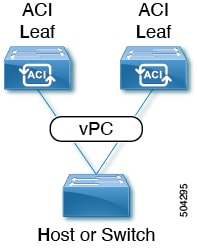
A virtual port channel (vPC) allows links that are physically connected to two different Cisco Application Centric Infrastructure (ACI) leaf nodes to appear as a single port channel (PC) to a third device, such as a network switch, server, any other networking device that supports link aggregation technology. vPCs consist of two Cisco ACI leaf switches designated as vPC peer switches. Of the vPC peers, one is primary and one is secondary. The system formed by the switches is referred to as a vPC domain.

Figure 4. vPC Domain

The following behavior is specific to the Cisco ACI vPC implementation:

  • No dedicated peer-link between the vPC peers. Instead, the fabric itself serves as the Multi-Chassis Trunking (MCT).

  • Peer reachability protocol: Cisco ACI uses the Zero Message Queue (ZMQ) instead of Cisco Fabric Services (CFS).

    • ZMQ is an open-source, high-performance messaging library that uses TCP as the transport.

    • This library is packaged as libzmq on the switch and linked into each application that needs to communicate with a vPC peer.

  • Peer reachability is not handled using a physical peer link. Instead, routing triggers are used to detect peer reachability.

    • The vPC manager registers with Unicast Routing Information Base (URIB) for peer route notifications.

    • When IS-IS discovers a route to the peer, URIB notifies the vPC manager, which in turn attempts to open a ZMQ socket with the peer.

    • When the peer route is withdrawn by IS-IS, the vPC manager is again notified by URIB, and the vPC manager brings down the MCT link.

ACI Virtual Port Channel Workflow

This workflow provides an overview of the steps required to configure a virtual port channel (vPC).

Figure 5. Virtual port channel configuration

1. Prerequisites

  • Ensure that you have read/write access privileges to the infra security domain.

  • Ensure that the target leaf switches with the necessary interfaces are available.


Note


When creating a vPC domain between two Leaf nodes, please considering the hardware model limitations:

  • Generation 1 switches are compatible only with other Generation 1 Switches. These switch models can be identified by the lack of “EX”, or “FX” at the end of the switch name. For example N9K-9312TX.

    Generation 2 and later switches can be mixed together in a vPC domain. These switch models can be identified with “EX”, “FX” or “FX2” at the end of the switch name. For example N9K-93108TC-EX, or N9K-9348GC-FXP.

Example:

Compatible vPC Switch Pairs:

  • N9K-9312TX & N9K-9312TX

  • N9K-93108TC-EX & N9K-9348GC-FXP

  • Nexus 93180TC-FX & Nexus 93180YC-FX

  • Nexus 93180YC-FX & Nexus 93180YC-FX

Incompatible vPC Switch Pairs:

  • N9K-9312TX & N9K-93108TC-EX

  • N9K-9312TX & Nexus 93180YC-FX


2. Configure the Virtual Port Channel

  1. On the APIC menu bar, navigate to Fabric > External Access Policies > Quick Start, and click Configure an interface, PC, and vPC to open the quick start wizard.

  2. Provide the specifications for the policy name, switch IDs and the interfaces the virtual port channel will use. Add the Interface Policy parameters, such as group port speed, storm control, CDP, LLDP. Add the Attached Device Type as an External Bridged Device and specify the VLAN and domain that will be used.

  3. Use the CLI show int command on the ACI leaf switches where the external switch is attached to verify that the switches and virtual port channel are configured accordingly.


Note


While this configuration enables hardware connectivity, no data traffic can flow without a valid application profile, EPG, and contract that is associated with this hardware configuration.


Configure the Application Profile

  1. On the APIC menu bar, navigate to Tenant > tenant-name > Quick Start, and click Create an application profile under the tenant quick start wizard.

  2. Configure the endpoint groups (EPGs), contracts, bridge domain, subnet, and context.

  3. Associate the application profile EPGs with the virtual port channel switch profile created above.

Virtual Port Channel Use Cases

vPC With the Same Leaf Switch Interfaces Across Two Leaf Switches With Combined Profiles

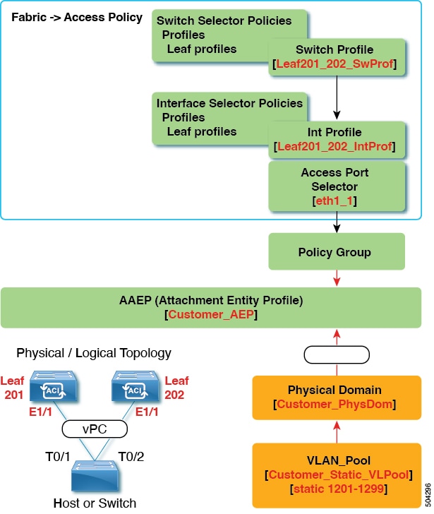
For the example of this use case, you define the following things:

  • A combined switch profile called Leaf201_202_SwProf (node 201 and node 202).

  • A combined interface profile called Leaf201_202_IntProf (node 201 and node 202).

  • An access port selector called Eth1_1 (under the Leaf201_202 interface profile) is pointing toward a vPC interface policy group.

  • The vPC interface policy group is pointing toward an AAEP called Customer_AEP.

  • The AEP (Customer_AEP) has an association with the Customer_PhysDom.

  • The Customer_PhysDom has an association with a VLAN pool called Customer_Static_VLPool.

Figure 6. vPC With the Same Leaf Switch Interfaces Across Two Leaf Switches With Combined Profiles

What This Configuration Does

On switches Leaf201 and Leaf202, configure port Eth1/1 to be part of a vPC. This vPC interface will have access to VLANs 1201 through 1299. Depending on the interface policy group, you can enable LACP Active and other interface specific policy configurations.

When to Use This Configuration

If you have dedicated pairs of compute leaf switches with nothing but vPC-connected servers, for example, this would be a solid use case for using combined-switch/interface profiles under your fabric access policies for those switches. You could preconfigure your switch, interface, access port selector, and vPC interface policy groups in such a way that allowed you to plug in 48 chassis-type servers with minimal effort.

vPC With the Same Leaf Switch Interfaces Across Two Leaf Switches with Individual Profiles

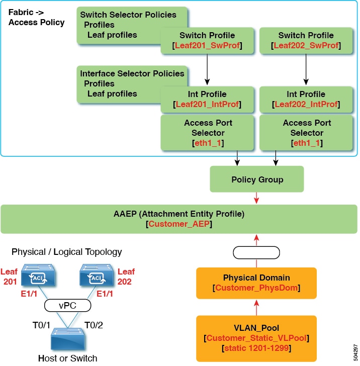
For the example of this use case, you define the following things:

  • Individual switch profiles called Leaf201_SwProf and Leaf202_SwProf (node 201 and node 202).

  • Individual interface profiles called Leaf201_IntProf and Leaf202_IntProf (node 201 and node 202)

  • Access port selectors called Eth1_1 (under the Leaf201 and Leaf202 interface profiles) is pointing toward the same vPC interface policy group.

  • The vPC interface policy group is pointing toward an AAEP called Customer_AEP.

  • The AEP (Customer_AEP) has an association with the Customer_PhysDom.

  • The Customer_PhysDom has an association with a VLAN pool called Customer_Static_VLPool.

Figure 7. vPC With the Same Leaf Switch Interfaces Across Two Leaf Switches with Individual Profiles

What This Configuration Does

On switches Leaf201 and Leaf202, configure port Eth1/1 to be a part of a vPC. This vPC interface will have access to VLANs 1201 through 1299. Depending on the interface policy group, you can enable LACP active and other interface specific policy configurations.

When to Use This Configuration

Use this configuration when you have leaf switches that support mixed workloads, such as compute, services, or Cisco Application Policy Infrastructure Controllers (APICs). In this case, having individual interface profiles allows for the most amount of flexibility, while allowing you to keep your Fabric > Access Policies configuration as clean and manageable as possible.

vPC With Different Leaf Switch Interfaces Across Two Leaf Switches With Individual Profiles

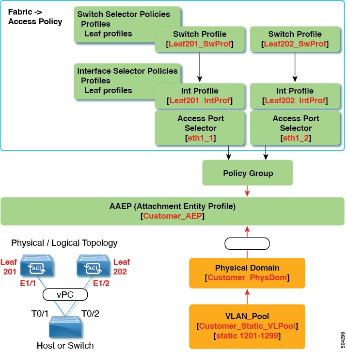
For the example of this use case, you define the following things:

  • Individual switch profiles called Leaf201_SwProf and Leaf202_SwProf (node 201 and node 202).

  • Individual interface profiles called Leaf201_IntProf and Leaf202_IntProf (node 201 and node 202)

  • An access port selector called Eth1_1 (under the Leaf201 interface profile) is pointing toward the same vPC interface policy group.

  • An access port selector called Eth1_2 (under the Leaf202 interface profile) is pointing toward the same vPC interface policy group.

  • The vPC interface policy group is pointing toward an AAEP called Customer_AEP.

  • The AEP (Customer_AEP) has an association with the Customer_PhysDom.

  • The Customer_PhysDom has an association with a VLAN pool called Customer_Static_VLPool.

Figure 8. vPC With Different Leaf Switch Interfaces Across Two Leaf Switchs With Individual Profiles

What This Configuration Does

On ports Eth1/1 on Leaf201 and Eth 1/2 on Leaf202, configure those ports to be a part of a vPC. This vPC interface will have access to VLANs 1201 through 1299. Depending on the interface policy group, you can enable LACP active and other interface specific policy configurations.

When to Use This Configuration

Use this configuration in a lab environment where you cannot use interfaces that match up. However, you must constantly refer to the GUI to determine where you plugged in your server. As a result, this configuration is cumbersome and is not ideal.


Note


Do not use this configuration in production.


Defining vPC Switch Pairs Using the GUI

This procedure defines vPC switch pairs using the GUI. We recommend that you keep the leaf switch peer group names simple as shown in the following example:

  • Leaf201_202

  • Leaf203_204

  • Leaf205_206

For naming and numbering best practices, see the Cisco ACI Object Naming and Numbering: Best Practices document:

https://www.cisco.com/c/en/us/td/docs/switches/datacenter/aci/apic/sw/kb/b-Cisco-ACI-Naming-and-Numbering.html

Procedure


Step 1

On the menu bar, choose Fabric > Access Policies.

Step 2

In the Navigation pane, choose Policies > Switch > Virtual Port Channel default.

Step 3

In the Explicit vPC Protection Groups table, click + and fill out the fields as follows:

  1. In the Name field, enter the vPC pair name.

    Example name: Leaf201_202. A name similar to the example easily identifies which two fabric nodes are vPC peers.

  2. In the ID field, enter the vPC pair ID (logical peer ID).

    Example ID: 201. The example uses the first node ID number of the pair to make it easier to correlate the ID with the vPC pair.

  3. In the Switch 1 and Switch 2 fields, choose the leaf switches for the vPC switch pair.

  4. Click Submit.


The vPC pair gets added to the Explicit vPC Protection Groups table. The Virtual IP value is an auto-generated IP address from the system tunnel endpoint (TEP) pool, and represents the virtual shared (Anycast) TEP of the vPC switch pair. That is, packets destined to vPC-connected endpoints of the vPC pair will use this Anycast VTEP to send the packets.

ACI Leaf Switch Virtual Port Channel Configuration Using the GUI

The procedure below uses a Quick Start wizard.


Note


This procedure provides the steps for attaching a trunked switch to a ACI leaf switch virtual port channel. The steps would be the same for attaching other kinds of devices to an ACI leaf switch interface.


Figure 9. Switch Virtual Port Channel Configuration


Note


LACP sets a port to the suspended state if it does not receive an LACP PDU from the peer. This can cause some servers to fail to boot up as they require LACP to logically bring-up the port. You can tune behavior to individual use by disabling LACP suspend individual. To do so, create a port channel policy in your vPC policy group, and after setting the mode to LACP active, remove Suspend Individual Port. Now the ports in the vPC will stay active and continue to send LACP packets.


Note


Adaptive Load Balancing (ALB) (based on ARP Negotiation) across virtual port channels is not supported in the ACI.


Before you begin

  • The ACI fabric is installed, APIC controllers are online, and the APIC cluster is formed and healthy.

  • An APIC fabric administrator account is available that will enable creating the necessary fabric infrastructure configurations.

  • The target leaf switches are registered in the ACI fabric and available.


Note


When creating a vPC domain between two leaf switches, both switches must be in the same switch generation, one of the following:

  • Generation 1 - Cisco Nexus N9K switches without “EX” on the end of the switch name; for example, N9K-9312TX

  • Generation 2 – Cisco Nexus N9K switches with “EX” on the end of the switch model name; for example, N9K-93108TC-EX

Switches such as these two are not compatible vPC peers. Instead, use switches of the same generation.


Procedure


Step 1

On the APIC menu bar, navigate to Fabric > Access Policies > Quick Start, and click Configure an interface, PC, and vPC.

Step 2

In the Configure an interface, PC, and vPC work area, click the large green + to select switches.

The Select Switches To Configure Interfaces work area opens with the Quick option selected by default.

Step 3

Select switch IDs from the Switches drop-down list, name the profile, then click Save.

The saved policy displays in the Configured Switch Interfaces list.

Step 4

Configure the Interface Policy Group and Attached Device Type that the virtual port channel will use for the selected switches.

The interface policy group is a named policy that specifies the group of interface policies you will apply to the selected interfaces of the switch. Examples of interface policies include Link Level Policy (for example, 1gbit port speed), Storm Control Interface Policy, and so forth.

Note


The Attached Device Type domain is required for enabling an EPG to use the interfaces specified in the switch profile.

  1. Specify vpc the interface type (individual, PC, or vPC) to use.

  2. Specify the interface IDs to use.

  3. Specify the interface policies to use.

  4. Specify the attached device type to use. Choose External Bridged Devices for connecting a switch.

  5. Specify the Domain, and VLAN Range.

  6. Click Save to update the policy details, then click Submit to submit the switch profile to the APIC.

    The APIC creates the switch profile, along with the interface, selector, and attached device type policies.

Verification: Use the CLI show int command on the leaf switches where the external switch is attached to verify that the vPC is configured accordingly.


What to do next

This completes the switch virtual port channel configuration steps.


Note


While this configuration enables hardware connectivity, no data traffic can flow without a valid application profile, EPG, and contract that is associated with this hardware configuration.


Configuring Virtual Port Channels in Leaf Nodes and FEX Devices Using the NX-OS CLI

A virtual port channel (vPC) is an enhancement to port-channels that allows connection of a host or switch to two upstream leaf nodes to improve bandwidth utilization and availability. In NX-OS, vPC configuration is done in each of the two upstream switches and configuration is synchronized using peer link between the switches.


Note


When creating a vPC domain between two leaf switches, both switches must be in the same switch generation, one of the following:

  • Generation 1 - Cisco Nexus N9K switches without “EX” on the end of the switch name; for example, N9K-9312TX

  • Generation 2 – Cisco Nexus N9K switches with “EX” on the end of the switch model name; for example, N9K-93108TC-EX

Switches such as these two are not compatible vPC peers. Instead, use switches of the same generation.


The Cisco Application Centric Infrastructure (ACI) model does not require a peer link and vPC configuration can be done globally for both the upstream leaf nodes. A global configuration mode called vpc context is introduced in Cisco ACI and vPC interfaces are represented using a type interface vpc that allows global configuration applicable to both leaf nodes.

Two different topologies are supported for vPC in the Cisco ACI model: vPC using leaf ports and vPC over FEX ports. It is possible to create many vPC interfaces between a pair of leaf nodes and similarly, many vPC interfaces can be created between a pair of FEX modules attached to the leaf node pairs in a straight-through topology.

vPC considerations include:

  • The vPC name used is unique between leaf node pairs. For example, only one vPC 'corp' can be created per leaf pair (with or without FEX).

  • Leaf ports and FEX ports cannot be part of the same vPC.

  • Each FEX module can be part of only one instance of vPC corp.

  • vPC context allows configuration

  • The vPC context mode allows configuration of all vPCs for a given leaf pair. For vPC over FEX, the fex-id pairs must be specified either for the vPC context or along with the vPC interface, as shown in the following two alternative examples.

    (config)# vpc context leaf 101 102
    (config-vpc)# interface vpc Reg fex 101 101

    or

    (config)# vpc context leaf 101 102 fex 101 101
    (config-vpc)# interface vpc Reg

In the Cisco ACI model, vPC configuration is done in the following steps (as shown in the examples below).


Note


A VLAN domain is required with a VLAN range. It must be associated with the port-channel template.


  1. VLAN domain configuration (global config) with VLAN range

  2. vPC domain configuration (global config)

  3. Port-channel template configuration (global config)

  4. Associate the port channel template with the VLAN domain

  5. Port-channel configuration for vPC (global config)

  6. Configure ports to vPC in leaf nodes

  7. Configure Layer 2, Layer 3 for vPC in the vPC context

Procedure


Step 1

configure

Enters global configuration mode.

Example:

apic1# configure

Step 2

vlan-domainname[dynamic] [type domain-type]

Configures a VLAN domain for the virtual port-channel (here with a port-channel template).

Example:

apic1(config)# vlan-domain dom1 dynamic

Step 3

vlanrange

Configures a VLAN range for the VLAN domain and exits the configuration mode. The range can be a single VLAN or a range of VLANs.

Example:

apic1(config-vlan)# vlan 1000-1999
apic1(config-vlan)# exit

Step 4

vpc domain explicit domain-id leaf node-id1 node-id2

Configures a vPC domain between a pair of leaf nodes. You can specify the vPC domain ID in the explicit mode along with the leaf node pairs.

Alternative commands to configure a vPC domain are as follows:

  • vpc domain [consecutive | reciprocal]

    The consecutive and reciprocal options allow auto configuration of a vPC domain across all leaf nodes in the Cisco ACI fabric.

  • vpc domain consecutive domain-start leaf start-node end-node

    This command configures a vPC domain consecutively for a selected set of leaf node pairs.

Example:

apic1(config)# vpc domain explicit 1 leaf 101 102

Step 5

peer-dead-interval interval

Configures the time delay the Leaf switch waits to restore the vPC before receiving a response from the peer. If it does not receive a response from the peer within this time, the Leaf switch considers the peer dead and brings up the vPC with the role as a master. If it does receive a response from the peer it restores the vPC at that point. The range is from 5 seconds to 600 seconds. The default is 200 seconds.

Example:

apic1(config-vpc)# peer-dead-interval 10

Step 6

exit

Returns to global configuration mode.

Example:

apic1(config-vpc)# exit

Step 7

template port-channel channel-name

Creates a new port-channel or configures an existing port-channel (global configuration).

All vPCs are configured as port-channels in each leaf pair. The same port-channel name must be used in a leaf pair for the same vPC. This port-channel can be used to create a vPC among one or more pairs of leaf nodes. Each leaf node will have only one instance of this vPC.

Example:

apic1(config)# template port-channel corp

Step 8

vlan-domain membervlan-domain-name

Associates the port channel template with the previously configured VLAN domain.

Example:

vlan-domain member dom1

Step 9

switchport access vlan vlan-id tenant tenant-name application application-name epg epg-name

Deploys the EPG with the VLAN on all ports with which the port-channel is associated.

Example:

apic1(config-po-ch-if)# switchport access vlan 4 tenant ExampleCorp application Web epg webEpg

Step 10

channel-mode active

Note


A port-channel must be in active channel-mode for a vPC.

Example:

apic1(config-po-ch-if)# channel-mode active

Step 11

exit

Returns to configure mode.

Example:

apic1(config-po-ch-if)# exit

Step 12

leaf node-id1 node-id2

Specifies the pair of leaf switches to be configured.

Example:

apic1(config)# leaf 101-102

Step 13

interface typeleaf/interface-range

Specifies the interface or range of interfaces that you are configuring to the port-channel.

Example:

apic1(config-leaf)# interface ethernet 1/3-4

Step 14

[no] channel-group channel-name vpc

Assigns the interface or range of interfaces to the port-channel. Use the keyword no to remove the interface from the port-channel. To change the port-channel assignment on an interface, you can enter the channel-group command without first removing the interface from the previous port-channel.

Note


The vpc keyword in this command makes the port-channel a vPC. If the vPC does not already exist, a vPC ID is automatically generated and is applied to all member leaf nodes.

Example:

apic1(config-leaf-if)# channel-group corp vpc

Step 15

exit

Example:

apic1(config-leaf-if)# exit

Step 16

exit

Example:

apic1(config-leaf)# exit

Step 17

vpc context leaf node-id1 node-id2

The vPC context mode allows configuration of vPC to be applied to both leaf node pairs.

Example:

apic1(config)# vpc context leaf 101 102

Step 18

interface vpc channel-name

Example:

apic1(config-vpc)# interface vpc blue fex 102 102

Step 19

(Optional) [no] shutdown

Administrative state configuration in the vPC context allows changing the admin state of a vPC with one command for both leaf nodes.

Example:

apic1(config-vpc-if)# no shut

Example

This example shows how to configure a basic vPC.

apic1# configure
apic1(config)# vlan-domain dom1 dynamic
apic1(config-vlan)# vlan 1000-1999
apic1(config-vlan)# exit
apic1(config)# vpc domain explicit 1 leaf 101 102
apic1(config-vpc)# peer-dead-interval 10
apic1(config-vpc)# exit
apic1(config)# template port-channel corp
apic1(config-po-ch-if)# vlan-domain member dom1
apic1(config-po-ch-if)# channel-mode active
apic1(config-po-ch-if)# exit
apic1(config)# leaf 101-102
apic1(config-leaf)# interface ethernet 1/3-4
apic1(config-leaf-if)# channel-group corp vpc
apic1(config-leaf-if)# exit
apic1(config)# vpc context leaf 101 102

This example shows how to configure vPCs with FEX ports.

apic1(config-leaf)# interface ethernet 101/1/1-2
apic1(config-leaf-if)# channel-group Reg vpc
apic1(config)# vpc context leaf 101 102
apic1(config-vpc)# interface vpc corp
apic1(config-vpc-if)# exit
apic1(config-vpc)# interface vpc red fex 101 101
apic1(config-vpc-if)# switchport
apic1(config-vpc-if)# exit
apic1(config-vpc)# interface vpc blue fex 102 102
apic1(config-vpc-if)# shut

Configuring a Single Virtual Port Channel Across Two Switches Using the REST API

The two steps for creating a virtual port channel across two switches are as follows:

  • Create a fabricExplicitGEp: this policy specifies the leaf switch that pairs to form the virtual port channel.

  • Use the infra selector to specify the interface configuration.

The APIC performs several validations of the fabricExplicitGEp and faults are raised when any of these validations fail. A leaf can be paired with only one other leaf. The APIC rejects any configuration that breaks this rule. When creating a fabricExplicitGEp, an administrator must provide the IDs of both of the leaf switches to be paired. The APIC rejects any configuration which breaks this rule. Both switches must be up when fabricExplicitGEp is created. If one switch is not up, the APIC accepts the configuration but raises a fault. Both switches must be leaf switches. If one or both switch IDs corresponds to a spine, the APIC accepts the configuration but raises a fault.

Before you begin

  • The ACI fabric is installed, APIC controllers are online, and the APIC cluster is formed and healthy.

  • An APIC fabric administrator account is available that will enable creating the necessary fabric infrastructure configurations.

  • The target leaf switch and protocol(s) are configured and available.

Procedure


To create the fabricExplicitGEp policy and use the intra selector to specify the interface, send a post with XML such as the following example:

Example:

<fabricProtPol pairT="explicit">
<fabricExplicitGEp name="tG" id="2">
	<fabricNodePEp id=”18”/>
	<fabricNodePEp id=”25"/>
        </fabricExplicitGEp>
   </fabricProtPol>

Configuring a Virtual Port Channel on Selected Port Blocks of Two Switches Using the REST API

This policy creates a single virtual port channel (vPC) on leaf switches 18 and 25, using interfaces 1/10 to 1/15 on leaf 18, and interfaces 1/20 to 1/25 on leaf 25.

Before you begin

  • The ACI fabric is installed, APIC controllers are online, and the APIC cluster is formed and healthy.

  • An APIC fabric administrator account is available that will enable creating the necessary fabric infrastructure configurations.

  • The target leaf switch and protocol(s) are configured and available.


Note


When creating a vPC domain between two leaf switches, both switches must be in the same switch generation, one of the following:

  • Generation 1 - Cisco Nexus N9K switches without “EX” on the end of the switch name; for example, N9K-9312TX

  • Generation 2 – Cisco Nexus N9K switches with “EX” on the end of the switch model name; for example, N9K-93108TC-EX

Switches such as these two are not compatible vPC peers. Instead, use switches of the same generation.


Procedure


To create the vPC send a post with XML such as the following example:

Example:

<infraInfra dn="uni/infra">

       <infraNodeP name=”test1">
           <infraLeafS name="leafs" type="range">
                <infraNodeBlk name="nblk” 
                     from_=”18" to_=”18”/>
           </infraLeafS>
           <infraRsAccPortP tDn="uni/infra/accportprof-test1"/>	
       </infraNodeP>

       <infraNodeP name=”test2">
           <infraLeafS name="leafs" type="range">
                <infraNodeBlk name="nblk” 
                     from_=”25" to_=”25”/>
           </infraLeafS>
           <infraRsAccPortP tDn="uni/infra/accportprof-test2"/>	
       </infraNodeP>

       <infraAccPortP name="test1">
           <infraHPortS name="pselc" type="range">
                <infraPortBlk name="blk1” 
                     fromCard="1" toCard="1" 
                     fromPort="10" toPort=”15”/>
                <infraRsAccBaseGrp 
                     tDn="uni/infra/funcprof/accbundle-bndlgrp" />
            </infraHPortS>
       </infraAccPortP>

       <infraAccPortP name="test2">
            <infraHPortS name="pselc" type="range">
                 <infraPortBlk name="blk1” 
                      fromCard="1" toCard="1" 
                      fromPort=“20" toPort=”25”/>
            <infraRsAccBaseGrp 
                 tDn="uni/infra/funcprof/accbundle-bndlgrp" />
            </infraHPortS>
        </infraAccPortP>

        <infraFuncP>
              <infraAccBndlGrp name="bndlgrp" lagT=”node">
                   <infraRsHIfPol  tnFabricHIfPolName=“default"/>
                   <infraRsCdpIfPol tnCdpIfPolName=”default”/>
                   <infraRsLacpPol tnLacpLagPolName=”default"/>
              </infraAccBndlGrp>
        </infraFuncP>

</infraInfra>

Reflective Relay

Reflective Relay (802.1Qbg)

Reflective relay is a switching option beginning with Cisco APIC Release 2.3(1). Reflective relay—the tagless approach of IEEE standard 802.1Qbg—forwards all traffic to an external switch, which then applies policy and sends the traffic back to the destination or target VM on the server as needed. There is no local switching. For broadcast or multicast traffic, reflective relay provides packet replication to each VM locally on the server.

One benefit of reflective relay is that it leverages the external switch for switching features and management capabilities, freeing server resources to support the VMs. Reflective relay also allows policies that you configure on the Cisco APIC to apply to traffic between the VMs on the same server.

In the Cisco ACI, you can enable reflective relay, which allows traffic to turn back out of the same port it came in on. You can enable reflective relay on individual ports, port channels, or virtual port channels as a Layer 2 interface policy using the APIC GUI, NX-OS CLI, or REST API. It is disabled by default.

The term Virtual Ethernet Port Aggregator (VEPA) is also used to describe 802.1Qbg functionality.

Reflective Relay Support

Reflective relay supports the following:

  • IEEE standard 802.1Qbg tagless approach, known as reflective relay.

    Cisco APIC Release 2.3(1) release does not support the IEE standard 802.1Qbg S-tagged approach with multichannel technology.

  • Physical domains.

    Virtual domains are not supported.

  • Physical ports, port channels (PCs), and virtual port channels (vPCs).

    Cisco Fabric Extender (FEX) and blade servers are not supported. If reflective relay is enabled on an unsupported interface, a fault is raised, and the last valid configuration is retained. Disabling reflective relay on the port clears the fault.

  • Cisco Nexus 9000 series switches with EX or FX at the end of their model name.

Enabling Reflective Relay Using the GUI

Reflective relay is disabled by default; however, you can enable it on a port, port channel, or virtual port channel as a Layer 2 interface policy on the switch. You first configure a policy and then associate the policy with a policy group.

Before you begin

This procedure assumes that you have set up the Cisco Application Centric Infrastructure (ACI) fabric and installed the physical switches.

Procedure


Step 1

Choose Fabric > External Access Policies > > Interface Policies and then open the Policies folder.

Step 2

Right-click the L2 Interface folder and choose Create L2 Interface Policy.

Step 3

In the Create L2 Interface Policy dialog box, enter a name in the Name field.

Step 4

In the Reflective Relay (802.1Qbg) area, click enabled.

Step 5

Choose other options in the dialog box as needed.

Step 6

Click SUBMIT.

Step 7

In the Policies navigation pane, open the Policy Groups folder and click the Leaf Policy Groups folder.

Step 8

In the Leaf Policy Groups central pane, expand the ACTIONS drop-down list, and choose Create Leaf Access Port Policy Group, Create PC Interface Policy Group, Create vPC Interface Policy Group, or Create PC/vPC Override Policy Group.

Step 9

In the policy group dialog box, enter a name in the Name field.

Step 10

From the L2 Interface Policy drop-down list, choose the policy that you just created to enable Reflective Relay.

Step 11

Click Submit.


Enabling Reflective Relay Using the NX-OS CLI

Reflective relay is disabled by default; however, you can enable it on a port, port channel, or virtual port channel as a Layer 2 interface policy on the switch. In the NX-OS CLI, you can use a template to enable reflective relay on multiple ports or you can enable it on individual ports.

Before you begin

This procedure assumes that you have set up the Cisco Application Centric Infrastructure (ACI) fabric and installed the physical switches.

Procedure


Enable reflective relay on one or multiple ports:

Example:

This example enables reflective relay on a single port:
apic1(config)# leaf 101
apic1(config-leaf)# interface ethernet 1/2
apic1(config-leaf-if)# switchport vepa enabled
apic1(config-leaf-if)# exit
apic1(config-leaf)# exit

Example:

This example enables reflective relay on multiple ports using a template:
apic1(config)# template policy-group grp1
apic1(config-pol-grp-if)# switchport vepa enabled
apic1(config-pol-grp-if)# exit
apic1(config)# leaf 101
apic1(config-leaf)# interface ethernet 1/2-4
apic1(config-leaf-if)# policy-group grp1

Example:

This example enables reflective relay on a port channel:
apic1(config)# leaf 101
apic1(config-leaf)# interface port-channel po2                 
apic1(config-leaf-if)# switchport vepa enabled
apic1(config-leaf-if)# exit
apic1(config-leaf)# exit
apic1(config)# 

Example:

This example enables reflective relay on multiple port channels:
apic1(config)# template port-channel po1
apic1(config-if)# switchport vepa enabled
apic1(config-if)# exit
apic1(config)# leaf 101
apic1(config-leaf)# interface ethernet 1/3-4
apic1(config-leaf-if)# channel-group po1 
apic1(config-leaf-if)# exit
apic1(config-leaf)# exit

Example:

This example enables reflective relay on a virtual port channel:
apic1(config)# vpc domain explicit 1 leaf 101 102
apic1(config-vpc)# exit
apic1(config)# template port-channel po4
apic1(config-if)# exit
apic1(config)# leaf 101-102
apic1(config-leaf)# interface eth 1/11-12
apic1(config-leaf-if)# channel-group po4 vpc
apic1(config-leaf-if)# exit
apic1(config-leaf)# exit
apic1(config)# vpc context leaf 101 102
apic1(config-vpc)# interface vpc po4
apic1(config-vpc-if)# switchport vepa enabled

Enabling Reflective Relay Using the REST API

Reflective relay is disabled by default; however, you can enable it on a port, port channel, or virtual port channel as a Layer 2 interface policy on the switch.

Before you begin

This procedure assumes that you have set up the Cisco Application Centric Infrastructure (ACI) fabric and installed the physical switches.

Procedure


Step 1

Configure a Layer 2 Interface policy with reflective relay enabled.

Example:

<l2IfPol name=“VepaL2IfPol” vepa=“enabled"  /> 

Step 2

Apply the Layer 2 interface policy to a leaf access port policy group.

Example:

<infraAccPortGrp name=“VepaPortG">
    <infraRsL2IfPol tnL2IfPolName=“VepaL2IfPol”/>
</infraAccPortGrp>

Step 3

Configure an interface profile with an interface selector.

Example:

<infraAccPortP name=“vepa">
        <infraHPortS name="pselc" type="range">
             <infraPortBlk name="blk"
                 fromCard="1" toCard="1" fromPort="20" toPort="22">
             </infraPortBlk>
             <infraRsAccBaseGrp tDn="uni/infra/funcprof/accportgrp-VepaPortG" />
         </infraHPortS>
 </infraAccPortP>

Step 4

Configure a node profile with node selector.

Example:

<infraNodeP name=“VepaNodeProfile">
        <infraLeafS name=“VepaLeafSelector" type="range">
                 <infraNodeBlk name=“VepaNodeBlk" from_="101" to_="102"/>
        </infraLeafS>
               <infraRsAccPortP tDn="uni/infra/accportprof-vepa"/>
    </infraNodeP>

FEX Interfaces

Configuring Port, PC, and vPC Connections to FEX Devices

FEX connections and the profiles used to configure them can be created using the GUI, NX-OS Style CLI, or the REST API.

Interface profiles for configuring FEX connections are supported since Cisco APIC, Release 3.0(1k).

For information on how to configure them using the NX-OS style CLI, see the topics about configuring ports, PCs and vPCs using the NX-OS style CLI.

ACI FEX Guidelines

Observe the following guidelines when deploying a FEX:

  • Assuming that no leaf switch front panel ports are configured to deploy and EPG and VLANs, a maximum of 10,000 port EPGs are supported for being deployed using a FEX.

  • For each FEX port or vPC that includes FEX ports as members, a maximum of 20 EPGs per VLAN are supported.

  • A vPC with FEX interfaces ignores the minimum and maximum number of links configured in its port-channel policy. The vPC remains up even if the number of links is less than the minimum or greater than the maximum.

FEX Virtual Port Channels

The ACI fabric supports Cisco Fabric Extender (FEX) server-side virtual port channels (vPC), also known as an FEX straight-through vPC.


Note


When creating a vPC domain between two leaf switches, both switches must be in the same switch generation, one of the following:

  • Generation 1 - Cisco Nexus N9K switches without “EX” or "FX" on the end of the switch name; for example, N9K-9312TX

  • Generation 2 – Cisco Nexus N9K switches with “EX” or "FX" on the end of the switch model name; for example, N9K-93108TC-EX

Switches such as these two are not compatible vPC peers. Instead, use switches of the same generation.


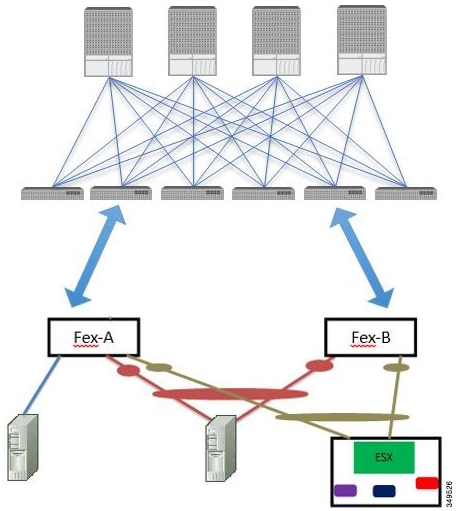
Figure 10. Supported FEX vPC Topologies

Supported FEX vPC port channel topologies include the following:

  • Both VTEP and non-VTEP hypervisors behind a FEX.

  • Virtual switches (such as AVS or VDS) connected to two FEXs that are connected to the ACI fabric (vPCs directly connected on physical FEX ports is not supported - a vPC is supported only on port channels).


Note


When using GARP as the protocol to n.jpgy of IP to MAC binding changes to different interfaces on the same FEX you must set the bridge domain mode to ARP Flooding and enable EP Move Detection Mode: GARP-based Detection, on the L3 Configuration page of the bridge domain wizard. This workaround is only required with Generation 1 switches. With Generation 2 switches or later, this is not an issue.


Configuring a Basic FEX Connection Using the GUI

The procedure below uses a Quick Start wizard that automatically creates some necessary policies for FEX deployment. The main steps are as follows:

  1. Configure a switch profile that includes an auto-generated FEX profile.

  2. Customize the auto-generated FEX Profile to enable attaching a server to a single FEX port.
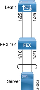
    Figure 11. Basic FEX Configuration


Note


This procedure provides the steps for attaching a server to the FEX. The steps would be the same for attaching any device to an ACI attached FEX.


Note


Configuring FEX connections with FEX IDs 165 to 199 is not supported in the APIC GUI. To use one of these FEX IDs, configure the profile using the NX-OS style CLI. For more information, see Configuring FEX Connections Using Interface Profiles with the NX-OS Style CLI.


Before you begin

  • The ACI fabric is installed, APIC controllers are online, and the APIC cluster is formed and healthy.

  • An APIC fabric administrator account is available that will enable creating the necessary fabric infrastructure configurations.

  • The target leaf switches, interfaces, and protocol(s) are configured and available.

  • The FEX is powered on and connected to the target leaf interfaces


Note


A maximum of eight members is supported in fabric port-channels connected to FEXs.


Procedure


Step 1

On the APIC, create a switch profile using the Fabric > Access Policies > Quick Start Configure Interface, PC, And vPC wizard.

  1. On the APIC menu bar, navigate to Fabric > Access Policies > Quick Start.

  2. In the Quick Start page, click the Configure an interface, PC, and vPC option to open the Configure Interface, PC And vPC wizard.

  3. In the Configure an interface, PC, and vPC work area, click the + to add a new switch profile.

  4. In the Select Switches To Configure Interfaces work area, click the Advanced radio button.

  5. Select the switch from the drop-down list of available switch IDs.

    Troubleshooting Tips:

    In this procedure, one switch is included in the profile. Selecting multiple switches allows the same profile to be used on multiple switches.

  6. Provide a name in the Switch Profile Name field.

  7. Click the + above the Fexes list to add a FEX ID and the switch ports to which it will connect to the switch profile.

    You must configure FEX IDs 165 - 199, using the NX-OS style CLI. See Configuring FEX Connections Using Interface Profiles with the NX-OS Style CLI.

  8. Click Save to save the changes. Click Submit to submit the switch profile to the APIC.

    The APIC auto-generates the necessary FEX profile (<switch policy name>_FexP<FEX ID>) and selector (<switch policy name>_ifselctor).

Verification: Use the CLI show fex command on the switch where the FEX is attached to verify that the FEX is online.

Step 2

Customize the auto-generated FEX Profile to enable attaching a server to a single FEX port.

  1. In the Navigation pane, locate the switch policy you just created in the policies list. You will also find the auto-generated FEX the <switch policy name>_FexP<FEX ID> profile.

  2. In the work pane of the <switch policy name>_FexP<FEX ID> profile, click the + to add a new entry to the Interface Selectors For FEX list.

    The Create Access Port Selector dialog opens.
  3. Provide a name for the selector.

  4. Specify the FEX interface IDs to use.

  5. Select an existing Interface Policy Group from the list or Create Access Port Policy Group.

    The access port policy group is a named policy that specifies the group of interface policies you will apply to the selected interfaces of the FEX. Examples of interface policies include Link Level Policy (for example, 1gbit port speed), Attach Entity Profile, Storm Control Interface Policy, and so forth.

    Note


    Within the interface policy group, the Attached Entity Profile is required for enabling an EPG to use the interfaces specified in the FEX port selector.

  6. Click Submit to submit the FEX profile to the APIC.

    The APIC updates the FEX profile.

Verification: Use the CLI show int command on the switch where the FEX is attached to verify that the FEX interface is configured accordingly.

This completes the basic FEX configuration steps.


What to do next


Note


While this configuration enables hardware connectivity, no data traffic can flow without a valid application profile, EPG, and contract that is associated with this hardware configuration.


Configuring FEX Port Channel Connections Using the GUI

The main steps are as follows:

  1. Configure an FEX profile to use FEX ports to form a port channel.

  2. Configure the port channel to enable attaching a server.
    Figure 12. FEX port channel


Note


This procedure provides the steps for attaching a server to the FEX port channel. The steps would be the same for attaching any device to an ACI attached FEX.

Before you begin

  • The ACI fabric is installed, APIC controllers are online, and the APIC cluster is formed and healthy.

  • An APIC fabric administrator account is available that will enable creating the necessary fabric infrastructure configurations.

  • The target leaf switch, interfaces, and protocol(s) are configured and available.

  • The FEX is configured, powered on, and connected to the target leaf interfaces

Procedure


Step 1

On the APIC, add a port channel to a FEX profile.

  1. On the APIC menu bar, navigate to Fabric > Access Policies > Interfaces > Leaf Interfaces > Profiles.

  2. In the Navigation Pane, select the FEX profile.

    APIC auto-generated FEX profile names are formed as follows: <switch policy name>_FexP<FEX ID>.

  3. In the FEX Profile work area, click the +to add a new entry to the Interface Selectors For FEX list.

    The Create Access Port Selector dialog opens.

Step 2

Customize the Create Access Port Selector to enable attaching a server to the FEX port channel.

  1. Provide a name for the selector.

  2. Specify the FEX interface IDs to use.

  3. Select an existing Interface Policy Group from the list or Create PC Interface Policy Group.

    The port channel interface policy group specifies the group of policies you will apply to the selected interfaces of the FEX. Examples of interface policies include Link Level Policy (for example, 1gbit port speed), Attach Entity Profile, Storm Control Interface Policy, and so forth.

    Note


    Within the interface policy group, the Attached Entity Profile is required for enabling an EPG to use the interfaces specified in the FEX port selector.

  4. In the Port Channel Policy option, select static or dynamic LACP according to the requirements of your configuration.

  5. Click Submit to submit the updated FEX proflle to the APIC.

    The APIC updates the FEX profile.

Verification: Use the CLI show port-channel summary command on the switch where the FEX is attached to verify that the port channel is configured accordingly.


What to do next

This completes the FEX port channel configuration steps.


Note


While this configuration enables hardware connectivity, no data traffic can flow without a valid application profile, EPG, and contract that is associated with this hardware configuration.


Configuring FEX vPC Connections Using the GUI

The main steps are as follows:

  1. Configure two existing FEX profiles to form a virtual port channel.

  2. Configure the virtual port channel to enable attaching a server to the FEX port channel.

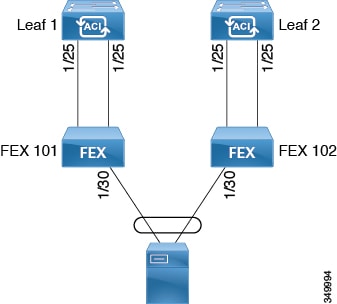
Figure 13. FEX virtual port channel


Note


This procedure provides the steps for attaching a server to the FEX virtual port channel. The steps would be the same for attaching any device to an ACI attached FEX.


Before you begin

  • The ACI fabric is installed, APIC controllers are online, and the APIC cluster is formed and healthy.

  • An APIC fabric administrator account is available that will enable creating the necessary fabric infrastructure configurations.

  • The target leaf switch, interfaces, and protocol(s) are configured and available.

  • The FEXes are configured, powered on, and connected to the target leaf interfaces


Note


When creating a vPC domain between two leaf switches, both switches must be in the same switch generation, one of the following:

  • Generation 1 - Cisco Nexus N9K switches without “EX” on the end of the switch name; for example, N9K-9312TX

  • Generation 2 – Cisco Nexus N9K switches with “EX” on the end of the switch model name; for example, N9K-93108TC-EX

Switches such as these two are not compatible vPC peers. Instead, use switches of the same generation.


Procedure


Step 1

On the APIC, add a virtual port channel to two FEX profiles.

  1. On the APIC menu bar, navigate to Fabric > External Access Policies > Interfaces > Leaf Interfaces > Profiles.

  2. In the Navigation Pane, select the first FEX profile.

    APIC auto-generated FEX profile names are formed as follows: <switch policy name>_FexP<FEX ID>.

  3. In the FEX Profile work area, click the +to add a new entry to the Interface Selectors For FEX list.

    The Create Access Port Selector dialog opens.

Step 2

Customize the Create Access Port Selector to enable attaching a server to the FEX virtual port channel.

  1. Provide a name for the selector.

  2. Specify the FEX interface ID to use.

    Typically, you will use the same interface ID on each FEX to form the virtual port channel.

  3. Select an existing Interface Policy Group from the list or Create VPC Interface Policy Group.

    The virtual port channel interface policy group specifies the group of policies you will apply to the selected interfaces of the FEX. Examples of interface policies include Link Level Policy (for example, 1gbit port speed), Attach Entity Profile, Storm Control Interface Policy, and so forth.

    Note


    Within the interface policy group, the Attached Entity Profile is required for enabling an EPG to use the interfaces specified in the FEX port selector.

  4. In the Port Channel Policy option, select static or dynamic LACP according to the requirements of your configuration.

  5. Click Submit to submit the updated FEX proflle to the APIC.

    The APIC updates the FEX profile.

Verification: Use the CLI show port-channel summary command on the switch where the FEX is attached to verify that the port channel is configured accordingly.

Step 3

Configure the second FEX to use the same Interface Policy Group just specified for the first FEX.

  1. In the FEX Profile work area of the second FEX profile, click the +to add a new entry to the Interface Selectors For FEX list.

    The Create Access Port Selector dialog opens.
  2. Provide a name for the selector.

  3. Specify the FEX interface ID to use.

    Typically, you will use the same interface ID on each FEX to form the virtual port channel.

  4. From the drop-down list, select the same virtual port channel Interface Policy Group just used in the first FEX profile.

    The virtual port channel interface policy group specifies the group of policies you will apply to the selected interfaces of the FEX. Examples of interface policies include Link Level Policy (for example, 1gbit port speed), Attach Entity Profile, Storm Control Interface Policy, and so forth.

    Note


    Within the interface policy group, the Attached Entity Profile is required for enabling an EPG to use the interfaces specified in the FEX port selector.

  5. Click Submit to submit the updated FEX proflle to the APIC.

    The APIC updates the FEX profile.

Verification: Use the CLI show vpc extended command on the switch where one of the FEXes is attached to verify that the virtual port channel is configured accordingly.


What to do next

This completes the FEX virtual port channel configuration steps.


Note


While this configuration enables hardware connectivity, no data traffic can flow without a valid application profile, EPG, and contract that is associated with this hardware configuration.


Configuring an FEX VPC Policy Using the REST API

This task creates a FEX virtual port channel (VPC) policy.

Before you begin

  • The ACI fabric is installed, APIC controllers are online, and the APIC cluster is formed and healthy.

  • An APIC fabric administrator account is available that will enable creating the necessary fabric infrastructure configurations.

  • The target leaf switch, interfaces, and protocol(s) are configured and available.

  • The FEXes are configured, powered on, and connected to the target leaf interfaces


Note


When creating a VPC domain between two leaf switches, both switches must be in the same switch generation, one of the following:

  • Generation 1 - Cisco Nexus N9K switches without “EX” on the end of the switch name; for example, N9K-9312TX

  • Generation 2 – Cisco Nexus N9K switches with “EX” on the end of the switch model name; for example, N9K-93108TC-EX

Switches such as these two are not compatible VPC peers. Instead, use switches of the same generation.

Procedure


To create the policy linking the FEX through a VPC to two switches, send a post with XML such as the following example:

Example:

<polUni>
<infraInfra dn="uni/infra">

<infraNodeP name="fexNodeP105">
    <infraLeafS name="leafs" type="range">
        <infraNodeBlk name="test" from_="105" to_="105"/>
    </infraLeafS>
    <infraRsAccPortP tDn="uni/infra/accportprof-fex116nif105" />
</infraNodeP>

<infraNodeP name="fexNodeP101">
    <infraLeafS name="leafs" type="range">
        <infraNodeBlk name="test" from_="101" to_="101"/>
    </infraLeafS>
    <infraRsAccPortP tDn="uni/infra/accportprof-fex113nif101" />
</infraNodeP>

<infraAccPortP name="fex116nif105">
   <infraHPortS name="pselc" type="range">
   <infraPortBlk name="blk1"
        fromCard="1" toCard="1" fromPort="45" toPort="48" >
   </infraPortBlk>
   <infraRsAccBaseGrp tDn="uni/infra/fexprof-fexHIF116/fexbundle-fex116" fexId="116" />
</infraHPortS>
</infraAccPortP>

<infraAccPortP name="fex113nif101">
   <infraHPortS name="pselc" type="range">
   <infraPortBlk name="blk1"
        fromCard="1" toCard="1" fromPort="45" toPort="48" >
   </infraPortBlk>
   <infraRsAccBaseGrp tDn="uni/infra/fexprof-fexHIF113/fexbundle-fex113" fexId="113" />
</infraHPortS>
</infraAccPortP>

<infraFexP name="fexHIF113">
    <infraFexBndlGrp name="fex113"/>
    <infraHPortS name="pselc-fexPC" type="range">
        <infraPortBlk name="blk"
            fromCard="1" toCard="1" fromPort="15" toPort="16" >
        </infraPortBlk>
        <infraRsAccBaseGrp tDn="uni/infra/funcprof/accbundle-fexPCbundle" />
    </infraHPortS>
        <infraHPortS name="pselc-fexVPC" type="range">
        <infraPortBlk name="blk"
            fromCard="1" toCard="1" fromPort="1" toPort="8" >
        </infraPortBlk>
        <infraRsAccBaseGrp tDn="uni/infra/funcprof/accbundle-fexvpcbundle" />
    </infraHPortS> 
    <infraHPortS name="pselc-fexaccess" type="range">
        <infraPortBlk name="blk" 
            fromCard="1" toCard="1" fromPort="47" toPort="47">
        </infraPortBlk>
        <infraRsAccBaseGrp tDn="uni/infra/funcprof/accportgrp-fexaccport" />
     </infraHPortS>
    
</infraFexP>

<infraFexP name="fexHIF116">
    <infraFexBndlGrp name="fex116"/>
    <infraHPortS name="pselc-fexPC" type="range">
        <infraPortBlk name="blk"
            fromCard="1" toCard="1" fromPort="17" toPort="18" >
        </infraPortBlk>
        <infraRsAccBaseGrp tDn="uni/infra/funcprof/accbundle-fexPCbundle" />
    </infraHPortS>  
        <infraHPortS name="pselc-fexVPC" type="range">
        <infraPortBlk name="blk"
            fromCard="1" toCard="1" fromPort="1" toPort="8" >
        </infraPortBlk>
        <infraRsAccBaseGrp tDn="uni/infra/funcprof/accbundle-fexvpcbundle" /> 
      </infraHPortS>   
      <infraHPortS name="pselc-fexaccess" type="range">
        <infraPortBlk name="blk" 
            fromCard="1" toCard="1" fromPort="47" toPort="47">
        </infraPortBlk>
        <infraRsAccBaseGrp tDn="uni/infra/funcprof/accportgrp-fexaccport" />
     </infraHPortS>
      
      
</infraFexP>

<infraFuncP>
<infraAccBndlGrp name="fexPCbundle" lagT="link">
    <infraRsLacpPol tnLacpLagPolName='staticLag'/>
    <infraRsHIfPol tnFabricHIfPolName="1GHIfPol" />
    <infraRsAttEntP tDn="uni/infra/attentp-fexvpcAttEP"/>
</infraAccBndlGrp>

<infraAccBndlGrp name="fexvpcbundle" lagT="node">
    <infraRsLacpPol tnLacpLagPolName='staticLag'/>
    <infraRsHIfPol tnFabricHIfPolName="1GHIfPol" />
    <infraRsAttEntP tDn="uni/infra/attentp-fexvpcAttEP"/>
</infraAccBndlGrp>
</infraFuncP>


<fabricHIfPol name="1GHIfPol" speed="1G" />
<infraAttEntityP name="fexvpcAttEP">
    <infraProvAcc name="provfunc"/>
    <infraRsDomP tDn="uni/phys-fexvpcDOM"/>
</infraAttEntityP>

<lacpLagPol dn="uni/infra/lacplagp-staticLag"
    ctrl="susp-individual,graceful-conv"
    minLinks="2"
    maxLinks="16">
</lacpLagPol>

Configuring FEX Connectivity to an ACI leaf switch Using Profiles with the NX-OS-Style CLI

Use this procedure to configure FEX connections to leaf nodes using the NX-OS style CLI.


Note


Configuring FEX connections with FEX IDs 165 to 199 is not supported in the Cisco Application Policy Infrastructure Controller (APIC) GUI. To use one of these FEX IDs, configure the profile using the following commands.


Procedure


Step 1

configure

Enters global configuration mode.

Example:

apic1# configure

Step 2

leaf-interface-profile name

Specifies the leaf interface profile to be configured.

Example:

apic1(config)# leaf-interface-profile fexIntProf1

Step 3

leaf-interface-group name

Specifies the interface group to be configured.

Example:

apic1(config-leaf-if-profile)# leaf-interface-group leafIntGrp1

Step 4

fex associate fex-id [template template-typefex-template-name]

Attaches a FEX module to a leaf node. Use the optional template keyword to specify a template to be used. If it does not exist, the system creates a template with the name and type you specified.

Example:

apic1(config-leaf-if-group)# fex associate 101

Example

This merged example configures a leaf interface profile for FEX connections with ID 101.

apic1# configure
apic1(config)# leaf-interface-profile fexIntProf1
apic1(config-leaf-if-profile)# leaf-interface-group leafIntGrp1
apic1(config-leaf-if-group)# fex associate 101

Configuring Port Profiles to Change Ports from Uplink to Downlink or Downlink to Uplink

Configuring Port Profiles

Prior to Cisco Application Policy Infrastructure Controller (APIC) release 3.1(1), conversion from uplink port to downlink port or downlink port to uplink port (in a port profile) was not supported on Cisco Application Centric Infrastructure (ACI) leaf switches. Starting with Cisco APIC release 3.1(1), uplink and downlink conversion is supported on Cisco Nexus 9000 series switches with names that end in EX or FX, and later (for example, N9K-C9348GC-FXP). A FEX connected to converted downlinks is also supported.

This functionality is supported on the following Cisco switches:

  • N9K-C9348GC-FXP

  • N9K-C93180LC-EX and N9K-C93180YC-FX

  • N9K-C93108TC-EX and N9K-C93108TC-FX (only uplink to downlink conversion is supported)

  • N9K-C9336C-FX2 (only downlink to uplink conversion is supported)

Restrictions

  • Fast Link Failover policies and port profiles are not supported on the same port. If port profile is enabled, Fast Link Failover cannot be enabled or vice versa.

  • The last 2 uplink ports of supported TOR switches cannot be converted to downlink ports (they are reserved for uplink connections.)

  • Up to Cisco APIC release 3.2, port profiles and breakout ports are not supported on the same ports.

  • With Cisco APIC release 3.2 and later, dynamic breakouts (both 100Gb and 40Gb) are supported on profiled QSFP ports on the N9K-C93180YC-FX switch. Breakout and port profile are supported together for conversion of uplink to downlink on ports 49-52. Breakout (both 10g-4x or 25g-4x options) is supported on downlink profiled ports.

  • Reloading a switch after changing a switch's port profile configuration interrupts traffic through the data plane.

Guidelines

In converting uplinks to downlinks and downlinks to uplinks, consider the following guidelines.

Subject

Guideline

Decommissioning nodes with port profiles

If a decommissioned node has the Port Profile feature deployed on it, the port conversions are not removed even after decommissioning the node. It is necessary to manually delete the configurations after decommission, for the ports to return to the default state. To do this, log onto the switch, run the setup-clean-config.sh script, and wait for it to run. Then, enter the reload command.

FIPS

When you enable or disable Federal Information Processing Standards (FIPS) on a Cisco ACI fabric, you must reload each of the switches in the fabric for the change to take effect. The configured scale profile setting is lost when you issue the first reload after changing the FIPS configuration. The switch remains operational, but it uses the default scale profile. This issue does not happen on subsequent reloads if the FIPS configuration has not changed.

FIPS is supported on Cisco NX-OS release 13.1(1) or later.

If you must downgrade the firmware from a release that supports FIPS to a release that does not support FIPS, you must first disable FIPS on the Cisco ACI fabric and reload all the switches in the fabric for the FIPS configuration change.

Maximum uplink port limit

When the maximum uplink port limit is reached and ports 25 and 27 are converted from uplink to downlink and back to uplink on Cisco 93180LC-EX switches:

On Cisco 93180LC-EX Switches, ports 25 and 27 are the native uplink ports. Using the port profile, if you convert port 25 and 27 to downlink ports, ports 29, 30, 31, and 32 are still available as four native uplink ports. Because of the threshold on the number of ports (which is maximum of 12 ports) that can be converted, you can convert 8 more downlink ports to uplink ports. For example, ports 1, 3, 5, 7, 9, 13, 15, 17 are converted to uplink ports and ports 29, 30, 31 and 32 are the 4 native uplink ports (the maximum uplink port limit on Cisco 93180LC-EX switches).

When the switch is in this state and if the port profile configuration is deleted on ports 25 and 27, ports 25 and 27 are converted back to uplink ports, but there are already 12 uplink ports on the switch (as mentioned earlier). To accommodate ports 25 and 27 as uplink ports, 2 random ports from the port range 1, 3, 5, 7, 9, 13, 15, 17 are denied the uplink conversion and this situation cannot be controlled by the user.

Therefore, it is mandatory to clear all the faults before reloading the leaf node to avoid any unexpected behavior regarding the port type. It should be noted that if a node is reloaded without clearing the port profile faults, especially when there is a fault related to limit-exceed, the port might not be in an expected operational state.

Breakout Limitations

Switch

Releases

Limitations

N9K-C9332PQ

Cisco APIC 2.2 (1) and later

  • 40Gb dynamic breakouts into 4X10Gb ports are supported.

  • Ports 13 and 14 do not support breakouts.

  • Port profiles and breakouts are not supported on the same port.

N9K-C93180LC-EX

Cisco APIC 3.1(1) and later

  • 40Gb and 100Gb dynamic breakouts are supported on ports 1 through 24 on odd numbered ports.

  • When the top ports (odd ports) are broken out, then the bottom ports (even ports) are error disabled.

  • Port profiles and breakouts are not supported on the same port.

N9K-C9336C-FX2

Cisco APIC 3.1(2) and later

  • 40Gb and 100Gb dynamic breakouts are supported on ports 1 through 30.

  • Port profiles and breakouts are not supported on the same port.

N9K-C93180YC-FX

Cisco APIC 3.2(1) and later

  • 40Gb and 100Gb dynamic breakouts are supported on ports 49 though 52, when they are on profiled QSFP ports. To use them for dynamic breakout, perform the following steps:

    • Convert ports 49-52 to front panel ports (downlinks).

    • Perform a port-profile reload, using one of the following methods:

      • In the Cisco APIC GUI, navigate to Fabric > Inventory > Pod > Leaf, right-click Chassis and choose Reload.

      • In the iBash CLI, enter the reload command.

    • Apply breakouts on the profiled ports 49-52.

  • Ports 53 and 54 do not support either port profiles or breakouts.

Port Profile Configuration Summary

The following table summarizes supported uplinks and downlinks for the switches that support port profile conversions from Uplink to Downlink and Downlink to Uplink.

Switch Model

Default Links

Max Uplinks (Fabric Ports)

Max Downlinks (Server Ports)

Release Supported

N9K-C9348GC-FXP

48 x 100M/1G BASE-T downlinks

4 x 10/25-Gbps SFP28 downlinks

2 x 40/100-Gbps QSFP28 uplinks

48 x 100M/1G BASE-T downlinks

4 x 10/25-Gbps SFP28 uplinks

2 x 40/100-Gbps QSFP28 uplinks

Same as default port configuration

3.1(1i)

N9K-C93180LC-EX

24 x 40-Gbps QSFP28 downlinks(1-24)

2 x 40/100-Gbps QSFP28 uplinks(25, 27)

4 x 40/100-Gbps QSFP28 uplinks(29-32)

Or

12 x 100-Gbps QSFP28 downlinks(odd number from 1-24)

2 x 40/100-Gbps QSFP28 uplinks(25, 27)

4 x 40/100-Gbps QSFP28 uplinks(29-32)

18 x 40-Gbps QSFP28 downlinks (from 1-24)

6 x 40-Gbps QSFP28 uplinks(from 1-24)

2 x 40/100-Gbps QSFP28 uplinks(25, 27)

4 x 40/100-Gbps QSFP28 uplinks(29-32)

Or

6 x 100-Gbps QSFP28 downlinks(odd number from 1-24)

6 x 100-Gbps QSFP28 uplinks(odd number from 1-24)

2 x 40/100-Gbps QSFP28 uplinks(25, 27)

4 x 40/100-Gbps QSFP28 uplinks(29-32)

24 x 40-Gbps QSFP28 downlinks(1-24)

2 x 40/100-Gbps QSFP28 downlinks(25, 27)

4 x 40/100-Gbps QSFP28 uplinks(29-32)

Or

12 x 100-Gbps QSFP28 downlinks(odd number from 1-24)

2 x 40/100-Gbps QSFP28 downlinks (25, 27)

4 x 40/100-Gbps QSFP28 uplinks(29-32)

3.1(1i)

N9K-C93180YC-EX

N9K-C93180YC-FX

48 x 10/25-Gbps fiber downlinks

6 x 40/100-Gbps QSFP28 uplinks

Same as default port configuration

48 x 10/25-Gbps fiber downlinks

4 x 40/100-Gbps QSFP28 downlinks

2 x 40/100-Gbps QSFP28 uplinks

3.1(1i)

48 x 10/25-Gbps fiber uplinks

6 x 40/100-Gbps QSFP28 uplinks

4.0(1)

N9K-C93108TC-EX

N9K-C93108TC-FX

48 x 10GBASE-T downlinks

6 x 40/100-Gbps QSFP28 uplinks

Same as default port configuration

48 x 10/25-Gbps fiber downlinks

4 x 40/100-Gbps QSFP28 downlinks

2 x 40/100-Gbps QSFP28 uplinks

3.1

N9K-C9336C-FX2

30 x 40/100-Gbps QSFP28 downlinks

6 x 40/100-Gbps QSFP28 uplinks

18 x 40/100-Gbps QSFP28 downlinks

18 x 40/100-Gbps QSFP28 uplinks

Same as default port configuration

3.2(1i)

18 x 40/100-Gbps QSFP28 downlinks

18 x 40/100-Gbps QSFP28 uplinks

34 x 40/100-Gbps QSFP28 downlinks

2 x 40/100-Gbps QSFP28 uplinks

3.2(3i)

36 x 40/100-Gbps QSFP28 uplinks

34 x 40/100-Gbps QSFP28 downlinks

2 x 40/100-Gbps QSFP28 uplinks

4.1

N9K-93240YC-FX2

48 x 10/25-Gbps fiber downlinks

12 x 40/100-Gbps QSFP28 uplinks

Same as default port configuration

48 x 10/25-Gbps fiber downlinks

10 x 40/100-Gbps QSFP28 downlinks

2 x 40/100-Gbps QSFP28 uplinks

4.0(1)

48 x 10/25-Gbps fiber uplinks

12 x 40/100-Gbps QSFP28 uplinks

4.1

N9K-C93216TC-FX2

96 x 10G BASE-T downlinks

12 x 40/100-Gbps QSFP28 uplinks

Same as default port configuration

96 x 10G BASE-T downlinks

10 x 40/100-Gbps QSFP28 downlinks

2 x 40/100-Gbps QSFP28 uplinks

4.1.2

N9K-C93360YC-FX2

96 x 10/25-Gbps SFP28 downlinks

12 x 40/100-Gbps QSFP28 uplinks

44 x 10/25Gbps SFP28 downlinks

52 x 10/25Gbps SFP28 uplinks

12 x 40/100Gbps QSFP28 uplinks

96 x 10/25-Gbps SFP28 downlinks

10 x 40/100-Gbps QSFP28 downlinks

2 x 40/100-Gbps QSFP28 uplinks

4.1.2

Configuring a Port Profile Using the GUI

This procedure explains how to configure a port profile, which determines the port type: uplink or downlink.

Before you begin

  • The ACI fabric is installed, APIC controllers are online, and the APIC cluster is formed and healthy.

  • An APIC fabric administrator account is available that will enable creating or modifying the necessary fabric infrastructure configurations.

  • The target leaf switches are registered in the ACI fabric and available.

Procedure


Step 1

From the Fabric menu, select Inventory.

Step 2

In the left navigation pane of the Inventory screen, select Topology.

Step 3

Under Topology tab, select the Interface tab in the right navigation pane.

Step 4

Select the mode as Configuration.

Step 5

Add a leaf switch by clicking on the + icon (Add Switches) in the table menu.

Step 6

In the Add Switches table, select the Switch ID and click Add Selected.

When you select the port, the available option is highlighted.

Step 7

Select the ports and choose the new port type as Uplink or Downlink.

The last two ports are reserved for uplink. These cannot be converted to downlink ports.

Step 8

After clicking uplink or downlink, click Submit (reload the switch on your own later) or Submit and Reload Switch.

Note


Reload the switch for the change in the uplink or downlink configuration to take effect.


Configuring a Port Profile Using the NX-OS Style CLI

To configure a port profile using the NX-OS style CLI, perform the following steps:

Before you begin

  • The ACI fabric is installed, APIC controllers are online, and the APIC cluster is formed and healthy.

  • An APIC fabric administrator account is available that will enable creating or modifying the necessary fabric infrastructure configurations.

  • The target leaf switches are registered in the ACI fabric and available.

Procedure


Step 1

configure

Enters global configuration mode.

Example:

apic1# configure

Step 2

leaf node-id

Specifies the leaf or leaf switches to be configured.

Example:

apic1(config)# leaf 102

Step 3

interface type

Specifies the interface that you are configuring. You can specify the interface type and identity. For an Ethernet port, use ethernet slot / port.

Example:

apic1(config-leaf)# interface ethernet 1/2

Step 4

port-direction {uplink | downlink}

Determines the port direction or changes it. This example configures the port to be a downlink.

Note


On the N9K-C9336C-FX switch, changing a port from uplink to downlink is not supported.

Example:

apic1(config-leaf-if)# port-direction downlink

Step 5

Log on to the leaf switch where the port is located and enter the reload command.


Configuring a Port Profile Using the REST API

Before you begin

  • The ACI fabric is installed, APIC controllers are online, and the APIC cluster is formed and healthy.

  • An APIC fabric administrator account is available that will enable creating or modifying the necessary fabric infrastructure configurations.

  • The target leaf switches are registered in the ACI fabric and available.

Procedure


Step 1

To create a port profile that converts a downlink to an uplink, send a post with XML such as the following:

<!-- /api/node/mo/uni/infra/prtdirec.xml -->
<infraRsPortDirection tDn="topology/pod-1/paths-106/pathep-[eth1/7]" direc=“UpLink” />

Step 2

To create a port profile that converts an uplink to a downlink, send a post with XML such as the following:

Example:

<!-- /api/node/mo/uni/infra/prtdirec.xml -->
<infraRsPortDirection tDn="topology/pod-1/paths-106/pathep-[eth1/52]" direc=“DownLink” />

Verifying Port Profile Configuration and Conversion Using the NX-OS Style CLI

You can verify the configuration and the conversion of the ports using the show interface brief CLI command.


Note


Port profile can be deployed only on the top ports of a Cisco N9K-C93180LC-EX switch, for example, 1, 3, 5, 7, 9, 11, 13, 15, 17, 19, 21, and 23. When the top port is converted using the port profile, the bottom ports are hardware disabled. For example, if Eth 1/1 is converted using the port profile, Eth 1/2 is hardware disabled.


Procedure


Step 1

This example displays the output for converting an uplink port to downlink port. Before converting an uplink port to downlink port, the output is displayed in the example. The keyword routed denotes the port as uplink port.

Example:


switch# show interface brief
<snip>
Eth1/49          --      eth  routed  down   sfp-missing              100G(D)   --
Eth1/50          --      eth  routed  down   sfp-missing              100G(D)   --
<snip>

Step 2

After configuring the port profile and reloading the switch, the output is displayed in the example. The keyword trunk denotes the port as downlink port.

Example:


switch# show interface brief
<snip>
Eth1/49          0       eth  trunk   down   sfp-missing              100G(D)   --
Eth1/50          0       eth  trunk   down   sfp-missing              100G(D)   --
<snip>