EPGs

This chapter contains the following sections:

About Endpoint Groups

Endpoint Groups

The endpoint group (EPG) is the most important object in the policy model. The following figure shows where application EPGs are located in the management information tree (MIT) and their relation to other objects in the tenant.
Figure 1. Endpoint Groups


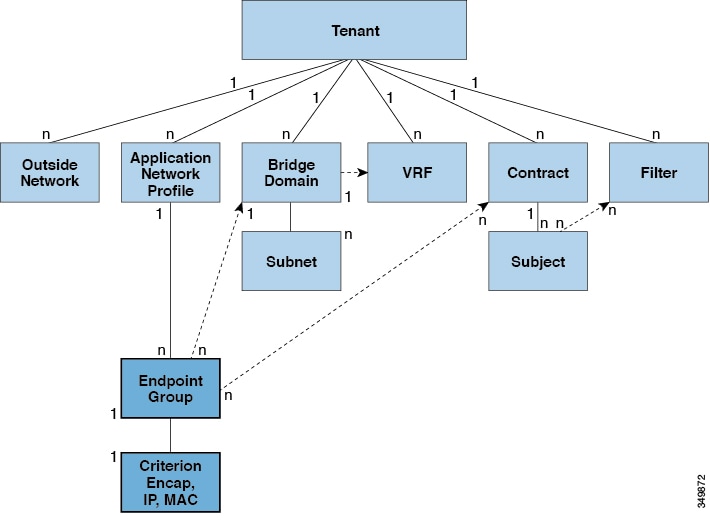
An EPG is a managed object that is a named logical entity that contains a collection of endpoints. Endpoints are devices that are connected to the network directly or indirectly. They have an address (identity), a location, attributes (such as version or patch level), and can be physical or virtual. Knowing the address of an endpoint also enables access to all its other identity details. EPGs are fully decoupled from the physical and logical topology. Endpoint examples include servers, virtual machines, network-attached storage, or clients on the Internet. Endpoint membership in an EPG can be dynamic or static.

The ACI fabric can contain the following types of EPGs:

  • Application endpoint group (fvAEPg)

  • Layer 2 external outside network instance endpoint group (l2extInstP)

  • Layer 3 external outside network instance endpoint group (l3extInstP)

  • Management endpoint groups for out-of-band (mgmtOoB) or in-band ( mgmtInB) access.

EPGs contain endpoints that have common policy requirements such as security, virtual machine mobility (VMM), QoS, or Layer 4 to Layer 7 services. Rather than configure and manage endpoints individually, they are placed in an EPG and are managed as a group.

Policies apply to EPGs, never to individual endpoints. An EPG can be statically configured by an administrator in the APIC, or dynamically configured by an automated system such as vCenter or OpenStack.


Note

When an EPG uses a static binding path, the encapsulation VLAN associated with this EPG must be part of a static VLAN pool. For IPv4/IPv6 dual-stack configurations, the IP address property is contained in the fvStIp child property of the fvStCEp MO. Multiple fvStIp objects supporting IPv4 and IPv6 addresses can be added under one fvStCEp object. When upgrading ACI from IPv4-only firmware to versions of firmware that support IPv6, the existing IP property is copied to an fvStIp MO.


Regardless of how an EPG is configured, EPG policies are applied to the endpoints they contain.

WAN router connectivity to the fabric is an example of a configuration that uses a static EPG. To configure WAN router connectivity to the fabric, an administrator configures an l3extInstP EPG that includes any endpoints within an associated WAN subnet. The fabric learns of the EPG endpoints through a discovery process as the endpoints progress through their connectivity life cycle. Upon learning of the endpoint, the fabric applies the l3extInstP EPG policies accordingly. For example, when a WAN connected client initiates a TCP session with a server within an application (fvAEPg) EPG, the l3extInstP EPG applies its policies to that client endpoint before the communication with the fvAEPg EPG web server begins. When the client server TCP session ends and communication between the client and server terminate, that endpoint no longer exists in the fabric.

Note

If a leaf switch is configured for static binding (leaf switches) under an EPG, the following restrictions apply:

  • The static binding cannot be overridden with a static path.

  • Interfaces in that switch cannot be used for routed external network (L3out) configurations.

  • Interfaces in that switch cannot be assigned IP addresses.


Virtual machine management connectivity to VMware vCenter is an example of a configuration that uses a dynamic EPG. Once the virtual machine management domain is configured in the fabric, vCenter triggers the dynamic configuration of EPGs that enable virtual machine endpoints to start up, move, and shut down as needed.

IP-Based EPGs

Although encapsulation-based EPGs are commonly used, IP-based EPGs are suitable in networks where there is a need for large numbers of EPGs that cannot be supported by Longest Prefix Match (LPM) classification. IP-based EPGs do not require allocating a network/mask range for each EPG, unlike LPM classification. Also, a unique bridge domain is not required for each IP-based EPG. The configuration steps for an IP-based EPG are like those for configuring a virtual IP-based EPG that is used in the Cisco AVS vCenter configuration.

Observe the following guidelines and limitations of IP-based EPGs:

  • IP-based EPGs are supported starting with the APIC 1.1(2x) and ACI switch 11.1(2x) releases on the following Cisco Nexus N9K switches:

    • Switches with "E" on the end of the switch name, for example, N9K-C9372PX-E.

    • Switches with "EX" on the end of the switch name, for example, N9K-93108TC-EX.

    The APIC raises a fault when you attempt to deploy IP-based EPGs on older switches that do not support them.

  • IP-based EPGs can be configured for specific IP addresses or subnets, but not IP address ranges.

  • IP-based EPGs are not supported in the following scenarios:

    • In combination with static EP configurations.

    • External, infrastructure tenant (infra) configurations will not be blocked, but they do not take effect, because there is no Layer 3 learning in this case.

    • In Layer 2-only bridge domains, IP-based EPG does not take effect, because there is no routed traffic in this case. If proxy ARP is enabled on Layer 3 bridge domains, the traffic is routed even if endpoints are in the same subnet. So IP-based EPG works in this case.

    • Configurations with a prefix that is used both for shared services and an IP-based EPG.

Access Policies Automate Assigning VLANs to EPGs

While tenant network policies are configured separately from fabric access policies, tenant policies are not activated unless their underlying access policies are in place. Fabric access external-facing interfaces connect to external devices such as virtual machine controllers and hypervisors, hosts, routers, or Fabric Extenders (FEXs). Access policies enable an administrator to configure port channels and virtual port channels, protocols such as LLDP, CDP, or LACP, and features such as monitoring or diagnostics.

Figure 2. Association of Endpoint Groups with Access Policies

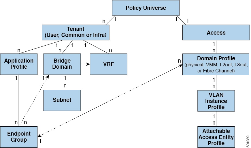
In the policy model, EPGs are tightly coupled with VLANs. For traffic to flow, an EPG must be deployed on a leaf port with a VLAN in a physical, VMM, L2out, L3out, or Fiber Channel domain. For more information, see Networking Domains.

In the policy model, the domain profile associated to the EPG contains the VLAN instance profile. The domain profile contains both the VLAN instance profile (VLAN pool) and the attacheable Access Entity Profile (AEP), which are associated directly with application EPGs. The AEP deploys the associated application EPGs to all the ports to which it is attached, and automates the task of assigning VLANs. While a large data center could easily have thousands of active virtual machines provisioned on hundreds of VLANs, the ACI fabric can automatically assign VLAN IDs from VLAN pools. This saves a tremendous amount of time, compared with trunking down VLANs in a traditional data center.

VLAN Guidelines

Use the following guidelines to configure the VLANs where EPG traffic will flow.

  • Multiple domains can share a VLAN pool, but a single domain can only use one VLAN pool.

  • To deploy multiple EPGs with same VLAN encapsulation on a single leaf switch, see Per Port VLAN.

Per Port VLAN

In ACI versions prior to the v1.1 release, a given VLAN encapsulation maps to only a single EPG on a leaf switch. If there is a second EPG which has the same VLAN encapsulation on the same leaf switch, the ACI raises a fault.

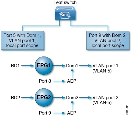
Starting with the v1.1 release, you can deploy multiple EPGs with the same VLAN encapsulation on a given leaf switch (or FEX), in the Per Port VLAN configuration, similar to the following diagram:

To enable deploying multiple EPGs using the same encapsulation number, on a single leaf switch, use the following guidelines:

  • EPGs must be associated with different bridge domains.

  • EPGs must be deployed on different ports.

  • Both the port and EPG must be associated with the same domain that is associated with a VLAN pool that contains the VLAN number.

  • Ports must be configured with portLocal VLAN scope.

For example, with Per Port VLAN for the EPGs deployed on ports 3 and 9 in the diagram above, both using VLAN-5, port 3 and EPG1 are associated with Dom1 (pool 1) and port 9 and EPG2 are associated with Dom2 (pool 2).

Traffic coming from port 3 is associated with EPG1, and traffic coming from port 9 is associated with EPG2.

This does not apply to ports configured for Layer 3 external outside connectivity.

When an EPG has more than one physical domain with overlapping VLAN pools, avoid adding more than one domain to the AEP that is used to deploy the EPG on the ports. This avoids the risk of traffic forwarding issues.

When an EPG has only one physical domain with overlapping VLAN pool, you can associate multiple domains with single AEP.

Only ports that have the vlanScope set to portlocal allow allocation of separate (Port, VLAN) translation entries in both ingress and egress directions. For a given port with the vlanScope set to portGlobal (the default), each VLAN used by an EPG must be unique on a given leaf switch.


Note

Per Port VLAN is not supported on interfaces configured with Multiple Spanning Tree (MST), which requires VLAN IDs to be unique on a single leaf switch, and the VLAN scope to be global.


Reusing VLAN Numbers Previously Used for EPGs on the Same Leaf Switch

If you have previously configured VLANs for EPGs that are deployed on a leaf switch port, and you want to reuse the same VLAN numbers for different EPGs on different ports on the same leaf switch, use a process, such as the following example, to set them up without disruption:

In this example, EPGs were previously deployed on a port associated with a domain including a VLAN pool with a range of 9-100. You want to configure EPGs using VLAN encapsulations from 9-20.

  1. Configure a new VLAN pool on a different port (with a range of, for example, 9-20).

  2. Configure a new physical domain that includes leaf ports that are connected to firewalls.

  3. Associate the physical domain to the VLAN pool you configured in step 1.

  4. Configure the VLAN Scope as portLocal for the leaf port.

  5. Associate the new EPGs (used by the firewall in this example) to the physical domain you created in step 2.

  6. Deploy the EPGs on the leaf ports.

VLAN Guidelines for EPGs Deployed on VPCs

Figure 3. VLANs for Two Legs of a VPC

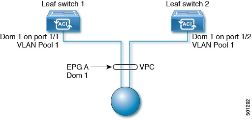
When an EPG is deployed on a VPC, it must be associated with the same domain (with the same VLAN pool) that is assigned to the leaf switch ports on the two legs of the VPC.

In this diagram, EPG A is deployed on a VPC that is deployed on ports on Leaf switch 1 and Leaf switch 2. The two leaf switch ports and the EPG are all associated with the same domain, containing the same VLAN pool.

Deploying an EPG on a Specific Port

Deploying an EPG on a Specific Port with APIC Using the GUI

Before you begin

The tenant where you deploy the EPG is already created.

Procedure


Step 1

On the menubar, click TENANTS.

Step 2

In the Navigation pane, expand the appropriate Tenant_name > Application Profiles.

Step 3

Right-click Application Profiles and click Create Application Profile.

Step 4

In the Create Application Profile dialog box, perform the following actions:

  1. In the Name field, enter a name for the application profile.

  2. Expand EPGs.

  3. In the Create Application EPG dialog box, in the Name field, enter an EPG name.

  4. In the Statically Link with Leaves/Paths field, check the checkbox for Statically Link with Leaves/Paths. (this is selected to specify on which port the EPG is required to be deployed). Click Next.

  5. In the Leaves/Paths area, expand Paths.

    In this example we are deploying the EPG on the port of a node. Alternatively, you could choose to deploy the EPG on a node.

  6. From the Path drop-down list, choose the appropriate node and port.

  7. In the Deployment Immediacy field drop-down list, choose the preferred deployment time.

  8. In the Mode field, choose the appropriate mode.

  9. In the Port Encap field, enter the secondary VLAN to be deployed.

  10. In the Primary Encap field, enter the primary VLAN to be deployed.

  11. Click Update, and click Finish.

Step 5

In the Navigation pane, expand Application Profiles to view the new application profile.

Step 6

Expand Application EPGs, to view the new EPG.

Step 7

Expand the EPG and click Static Bindings (Paths), and in the Properties pane, view the details of the static binding paths that are established.


Deploying an EPG on a Specific Port with APIC Using the NX-OS Style CLI

Procedure


Step 1

Configure a VLAN domain:

Example:


apic1(config)# vlan-domain dom1
apic1(config-vlan)# vlan 10-100
Step 2

Create a tenant:

Example:


apic1# configure
apic1(config)# tenant t1
Step 3

Create a private network/VRF:

Example:


apic1(config-tenant)# vrf context ctx1
apic1(config-tenant-vrf)# exit
Step 4

Create a bridge domain:

Example:


apic1(config-tenant)# bridge-domain bd1
apic1(config-tenant-bd)# vrf member ctx1
apic1(config-tenant-bd)# exit
Step 5

Create an application profile and an application EPG:

Example:


apic1(config-tenant)# application AP1
apic1(config-tenant-app)# epg EPG1
apic1(config-tenant-app-epg)# bridge-domain member bd1 
apic1(config-tenant-app-epg)# exit
apic1(config-tenant-app)# exit
apic1(config-tenant)# exit
Step 6

Associate the EPG with a specific port:

Example:


apic1(config)# leaf 1017
apic1(config-leaf)# interface ethernet 1/13
apic1(config-leaf-if)# vlan-domain member dom1
apic1(config-leaf-if)# switchport trunk allowed vlan 20 tenant t1 application AP1 epg EPG1
Note 

The vlan-domain and vlan-domain member commands mentioned in the above example are a pre-requisite for deploying an EPG on a port.


Deploying an EPG on a Specific Port with APIC Using the REST API

Before you begin

The tenant where you deploy the EPG is created.

Procedure


Deploy an EPG on a specific port.

Example:

<fvTenant name="<tenant_name>" dn="uni/tn-test1" >
    <fvCtx name="<network_name>" pcEnfPref="enforced" knwMcastAct="permit"/>
    <fvBD name="<bridge_domain_name>" unkMcastAct="flood" >
        <fvRsCtx tnFvCtxName="<network_name>"/>
    </fvBD>
    <fvAp name="<application_profile>" >
        <fvAEPg name="<epg_name>" >
            <fvRsPathAtt tDn="topology/pod-1/paths-1017/pathep-[eth1/13]" mode="regular" instrImedcy="immediate" encap="vlan-20"/>
        </fvAEPg>
    </fvAp>
</fvTenant>

Creating Domains, Attach Entity Profiles, and VLANs to Deploy an EPG on a Specific Port

Creating Domains, Attach Entity Profiles, and VLANs to Deploy an EPG on a Specific Port

This topic provides a typical example of how to create physical domains, Attach Entity Profiles (AEP), and VLANs that are mandatory to deploy an EPG on a specific port.


Note

All endpoint groups (EPGs) require a domain. Interface policy groups must also be associated with Attach Entity Profile (AEP), and the AEP must be associated with a domain, if the AEP and EPG have to be in same domain. Based on the association of EPGs to domains and of interface policy groups to domains, the ports and VLANs that the EPG uses are validated. The following domain types associate with EPGs:

  • Application EPGs

  • Layer 3 external outside network instance EPGs

  • Layer 2 external outside network instance EPGs

  • Management EPGs for out-of-band and in-band access

The APIC checks if an EPG is associated with one or more of these types of domains. If the EPG is not associated, the system accepts the configuration but raises a fault. The deployed configuration may not function properly if the domain association is not valid. For example, if the VLAN encapsulation is not valid for use with the EPG, the deployed configuration may not function properly.


Creating Domains, and VLANS to Deploy an EPG on a Specific Port Using the GUI

Before you begin

  • The tenant where you deploy the EPG is already created.

  • An EPG is statically deployed on a specific port.

Procedure


Step 1

On the menu bar, click FABRIC > Access Policies.

Step 2

In the Navigation pane, click Quick Start.

Step 3

In the Work pane, click Configure an interface, PC, and vPC.

Step 4

In the Configure Interface, PC, and vPC dialog box, click the + icon to select switches and perform the following actions:

  1. From the Switches drop-down list, check the check box for the desired switch.

  2. In the Switch Profile Name field, a switch name is automatically populated.

    Note 

    Optionally, you can enter a modified name.

  3. Click the + icon to configure the switch interfaces.

  4. In the Interface Type field, click the Individual radio button.

  5. In the Interfaces field, enter the range of desired interfaces.

  6. In the Interface Selector Name field, an interface name is automatically populated.

    Note 

    Optionally, you can enter a modified name.

  7. In the Interface Policy Group field, choose the Create One radio button.

  8. From the Link Level Policy drop-down list, choose the appropriate link level policy.

    Note 

    Create additional policies as desired, otherwise the default policy settings are available.

  9. From the Attached Device Type field, choose the appropriate device type.

  10. In the Domain field, click the Create One radio button.

  11. In the Domain Name field, enter a domain name.

  12. In the VLAN field, click the Create One radio button.

  13. In the VLAN Range field, enter the desired VLAN range. Click Save, and click Save again.

  14. Click Submit.

Step 5

On the menu bar, click TENANTS. In the Navigation pane, expand the appropriate Tenant_name > Application Profiles > Domains (VMs and Bare-Metals) > EPG_name and perform the following actions:

  1. Right-click Domains (VMs and Bare-Metals), and click Add Physical Domain Association.

  2. In the Add Physical Domain Association dialog box, from the Physical Domain Profile drop-down list, choose the appropriate domain.

  3. In the Deploy Immediacy field, click the desired radio button.

  4. In the Resolution Immediacy field, click the desired radio button. Click Submit.

    The AEP is associated with a specific port on a node and with a domain. The physical domain is associated with the VLAN pool and the Tenant is associated with this physical domain.

The switch profile and the interface profile are created. The policy group is created in the port block under the interface profile. The AEP is automatically created, and it is associated with the port block and with the domain. The domain is associated with the VLAN pool and the Tenant is associated with the domain.


Creating AEP, Domains, and VLANs to Deploy an EPG on a Specific Port Using the NX-OS Style CLI

Before you begin

  • The tenant where you deploy the EPG is already created.

  • An EPG is statically deployed on a specific port.

Procedure


Step 1

Create a VLAN domain and assign VLAN ranges:

Example:


apic1(config)# vlan-domain domP
apic1(config-vlan)# vlan 10
apic1(config-vlan)# vlan 25
apic1(config-vlan)# vlan 50-60
apic1(config-vlan)# exit
Step 2

Create an interface policy group and assign a VLAN domain to the policy group:

Example:


apic1(config)# template policy-group PortGroup
apic1(config-pol-grp-if)# vlan-domain member domP
Step 3

Create a leaf interface profile, assign an interface policy group to the profile, and  assign the interface IDs on which the profile will be applied:

Example:


apic1(config)# leaf-interface-profile InterfaceProfile1
apic1(config-leaf-if-profile)# leaf-interface-group range
apic1(config-leaf-if-group)# policy-group PortGroup    
apic1(config-leaf-if-group)# interface ethernet 1/11-13
apic1(config-leaf-if-profile)# exit
Step 4

Create a leaf profile, assign the leaf interface profile to the leaf profile, and  assign the leaf IDs on which the profile will be applied:

Example:


apic1(config)# leaf-profile SwitchProfile-1019          
apic1(config-leaf-profile)# leaf-interface-profile InterfaceProfile1 
apic1(config-leaf-profile)# leaf-group range                         
apic1(config-leaf-group)# leaf 1019                                
apic1(config-leaf-group)# 

Creating AEP, Domains, and VLANs to Deploy an EPG on a Specific Port Using the REST API

Before you begin

  • The tenant where you deploy the EPG is already created.

  • An EPG is statically deployed on a specific port.

Procedure


Step 1

Create the interface profile, switch profile and the Attach Entity Profile (AEP).

Example:

   <infraInfra>

      <infraNodeP  name="<switch_profile_name>" dn="uni/infra/nprof-<switch_profile_name>" >
           <infraLeafS  name="SwitchSeletor" descr="" type="range">
                <infraNodeBlk name="nodeBlk1" descr="" to_="1019" from_="1019"/>
           </infraLeafS>
          <infraRsAccPortP tDn="uni/infra/accportprof-<interface_profile_name>"/>
      </infraNodeP>

      <infraAccPortP name="<interface_profile_name>" dn="uni/infra/accportprof-<interface_profile_name>" >
           <infraHPortS  name="portSelector"  type="range">
                <infraRsAccBaseGrp tDn="uni/infra/funcprof/accportgrp-<port_group_name>" fexId="101"/>
               <infraPortBlk name="block2"  toPort="13" toCard="1" fromPort="11" fromCard="1"/>
         </infraHPortS>
     </infraAccPortP>

    <infraAccPortGrp  name="<port_group_name>" dn="uni/infra/funcprof/accportgrp-<port_group_name>" >
          <infraRsAttEntP tDn="uni/infra/attentp-<attach_entity_profile_name>"/>
          <infraRsHIfPol tnFabricHIfPolName="1GHifPol"/>
    </infraAccPortGrp>

    <infraAttEntityP  name="<attach_entity_profile_name>" dn="uni/infra/attentp-<attach_entity_profile_name>" >
         <infraRsDomP tDn="uni/phys-<physical_domain_name>"/>
    </infraAttEntityP>

<infraInfra>
Step 2

Create a domain.

Example:

<physDomP  name="<physical_domain_name>" dn="uni/phys-<physical_domain_name>">
    <infraRsVlanNs tDn="uni/infra/vlanns-[<vlan_pool_name>]-static"/>
</physDomP>
Step 3

Create a VLAN range.

Example:

<fvnsVlanInstP  name="<vlan_pool_name>" dn="uni/infra/vlanns-[<vlan_pool_name>]-static"  allocMode="static">
    <fvnsEncapBlk name="" descr="" to="vlan-25" from="vlan-10"/>
</fvnsVlanInstP>
Step 4

Associate the EPG with the domain.

Example:

<fvTenant  name="<tenant_name>" dn="uni/tn-" >
    <fvAEPg prio="unspecified" name="<epg_name>" matchT="AtleastOne" dn="uni/tn-test1/ap-AP1/epg-<epg_name>" descr="">
        <fvRsDomAtt tDn="uni/phys-<physical_domain_name>" instrImedcy="immediate" resImedcy="immediate"/>
    </fvAEPg>
</fvTenant>

Deploying EPGs to Multiple Interfaces Through Attached Entity Profiles

Deploying an Application EPG through an AEP or Interface Policy Group to Multiple Ports

Through the APIC Advanced GUI and REST API, you can associate attached entity profiles directly with application EPGs. By doing so, you deploy the associated application EPGs to all those ports associated with the attached entity profile in a single configuration.

Through the APIC REST API or the NX-OS style CLI, you can deploy an application EPG to multiple ports through an Interface Policy Group.

Deploying an EPG through an AEP to Multiple Interfaces Using the APIC Advanced GUI

You can quickly associate an application with an attached entity profile to quickly deploy that EPG over all the ports associated with that attached entity profile.

Before you begin

  • The target application EPG is created.

  • The VLAN pools has been created containing the range of VLANs you wish to use for EPG Deployment on the AEP.

  • The physical domain has been created and linked to the VLAN Pool and AEP.

  • The target attached entity profile is created and is associated with the ports on which you want to deploy the application EPG.

Procedure


Step 1

Navigate to the target attached entity profile.

  1. Open the page for the attached entity profile to use. In the Advanced GUI, click Fabric > Access Policies > Global Policies > Attachable Access Entity Profiles.

  2. Click the target attached entity profile to open its Attachable Access Entity Profile window.

Step 2

Click the Show Usage button to view the leaf switches and interfaces associated with this attached entity profile.

the application EPGs associated with this attached entity profile are deployed to all the ports on all the switches associated with this attached entity profile.

Step 3

Use the Application EPGs table to associate the target application EPG with this attached entity profile. Click + to add an application EPG entry. Each entry contains the following fields:

Field Action
Application EPGs

Use the drop down to choose the associated Tenant, Application Profile, and target application EPG.

Encap

Enter the name of the VLAN over which the target application EPG will communicate.

Primary Encap

If the application EPG requires a primary VLAN, enter the name of the primary VLAN.

Mode

Use the drop down to specify the mode in which data is transmitted:

  • Trunk -- Choose if traffic from the host is tagged with a VLAN ID.

  • Access -- Choose if traffic from the host is tagged with an 802.1p tag.

  • Access Untagged -- Choose if the traffic from the host is untagged.

Step 4

Click Submit.

the application EPGs associated with this attached entity profile are deployed to all the ports on all the switches associated with this attached entity profile.

Deploying an EPG through an Interface Policy Group to Multiple Interfaces Using the NX-OS Style CLI

In the NX-OS CLI, an attached entity profile is not explicitly defined to associate with an EPG for rapid deployment; instead the interface policy group is defined, assigned a domain, applied to all the ports associated with a VLAN and configured to include the application EPG to be deployed over that VLAN.

Before you begin

  • The target application EPG is created.

  • The VLAN pools has been created containing the range of VLANs you wish to use for EPG Deployment on the AEP.

  • The physical domain has been created and linked to the VLAN Pool and AEP.

  • The target attached entity profile is created and is associated with the ports on which you want to deploy the application EPG.

Procedure


Step 1

Associate the target EPG with the interface policy group.

The sample command sequence specifies an interface policy group pg3 associated with VLAN domain, domain1, and with VLAN 1261. The application EPG, epg47 is deployed to all interfaces associated with this policy group.

Example:

 apic1# configure terminal
apic1(config)# template policy-group pg3
apic1(config-pol-grp-if)# vlan-domain member domain1
apic1(config-pol-grp-if)# switchport trunk allowed vlan 1261 tenant tn10 application pod1-AP 
      epg epg47
Step 2

Check the target ports to ensure deployment of the policies of the interface policy group associated with application EPG.

The output of the sample show command sequence indicates that policy group pg3 is deployed on Ethernet port 1/20 on leaf switch 1017.

Example:

 apic1# show run leaf 1017 int eth 1/20
# Command: show running-config leaf 1017 int eth 1/20
# Time: Mon Jun 27 22:12:10 2016
  leaf 1017
    interface ethernet 1/20
      policy-group pg3
      exit
    exit
ifav28-ifc1#


Deploying an EPG through an AEP to Multiple Interfaces Using the REST API

The interface selectors in the AEP enable you to configure multiple paths for an AEPg. The following can be selected:

  1. A node or a group of nodes

  2. An interface or a group of interfaces

    The interfaces consume an interface policy group (and so an infra:AttEntityP).

  3. The infra:AttEntityP is associated to the AEPg, thus specifying the VLANs to use.

    An infra:AttEntityP can be associated with multiple AEPgs with different VLANs.

When you associate the infra:AttEntityP with the AEPg, as in 3, this deploys the AEPg on the nodes selected in 1, on the interfaces in 2, with the VLAN provided by 3.

In this example, the AEPg uni/tn-Coke/ap-AP/epg-EPG1 is deployed on interfaces 1/10, 1/11, and 1/12 of nodes 101 and 102, with vlan-102.

Before you begin

  • Create the target application EPG (AEPg).

  • Create the VLAN pool containing the range of VLANs you wish to use for EPG deployment with the Attached Entity Profile (AEP).

  • Create the physical domain and link it to the VLAN pool and AEP.

Procedure


To deploy an AEPg on selected nodes and interfaces, send a post with XML such as the following:

Example:

 <infraInfra dn="uni/infra">
   <infraNodeP name=“NodeProfile">
       <infraLeafS name=“NodeSelector" type="range">
          <infraNodeBlk name=“NodeBlok" from_="101" to_=“102”/>
          <infraRsAccPortP tDn="uni/infra/accportprof-InterfaceProfile"/>
        </infraLeafS>
   </<infraNodeP>
    
   <infraAccPortP name="InterfaceProfile">
      <infraHPortS name="InterfaceSelector" type="range">
          <infraPortBlk name=“ InterfaceBlock" fromCard="1" toCard="1" fromPort="10" toPort=“12"/>
          <infraRsAccBaseGrp tDn="uni/infra/funcprof/accportgrp-PortGrp" />
      </infraHPortS>
   </infraAccPortP>
 
   <infraFuncP>
       <infraAccPortGrp name="PortGrp”>
           <infraRsAttEntP  tDn="uni/infra/attentp-AttEntityProfile"/>
       </infraAccPortGrp>
   </infraFuncP>
 
   <infraAttEntityP name=“AttEntityProfile” >
       <infraGeneric name=“default” >
          <infraRsFuncToEpg tDn=“uni/tn-Coke/ap-AP/epg-EPG1” encap=“vlan-102"/>
       </infraGeneric>
   </infraAttEntityP>
</infraInfra>

Intra-EPG Isolation

Intra-EPG Endpoint Isolation

Intra-EPG endpoint isolation policies provide full isolation for virtual or physical endpoints; no communication is allowed between endpoints in an EPG that is operating with isolation enforced. Isolation enforced EPGs reduce the number of EPG encapsulations required when many clients access a common service but are not allowed to communicate with each other.

An EPG is isolation enforced for all ACI network domains or none. While the ACI fabric implements isolation directly to connected endpoints, switches connected to the fabric are made aware of isolation rules according to a primary VLAN (PVLAN) tag.


Note

If an EPG is configured with intra-EPG endpoint isolation enforced, these restrictions apply:
  • All Layer 2 endpoint communication across an isolation enforced EPG is dropped within a bridge domain.

  • All Layer 3 endpoint communication across an isolation enforced EPG is dropped within the same subnet.

  • Preserving QoS CoS priority settings is not supported when traffic is flowing from an EPG with isolation enforced to an EPG without isolation enforced.


Intra-EPG Isolation for Bare Metal Servers

Intra-EPG Isolation for Bare Metal Servers

Intra-EPG endpoint isolation policies can be applied to directly connected endpoints such as bare metal servers.

Examples use cases include the following:
  • Backup clients have the same communication requirements for accessing the backup service, buy they don't need to communicate with each other.

  • Servers behind a load balancer have the same communication requirements, but isolating them from each other protects against a server that is compromised or infected.

Figure 4. Intra-EPG Isolation for Bare Metal Servers


Bare metal EPG isolation is enforced at the leaf switch. Bare metal servers use VLAN encapsulation. All unicast, multicast and broadcast traffic is dropped (denied) within isolation enforced EPGs. ACI bridge-domains can have a mix of isolated and regular EPGs. Each Isolated EPG can have multiple VLANs where intra-vlan traffic is denied.

Configuring Intra-EPG Isolation for Bare Metal Servers Using the GUI

The port the EPG uses must be associated with a bare metal server interface in the physical domain that is used to connect the bare metal servers directly to leaf switches.

Procedure


Step 1

In a tenant, right click on an Application Profile, and open the Create Application EPG dialog box to perform the following actions:

  1. In the Name field, add the EPG name (intra_EPG-deny).

  2. For Intra EPG Isolation, click Enforced.

  3. In the Bridge Domain field, choose the bridge domain from the drop-down list (bd1).

  4. Check the Statically Link with Leaves/Paths check box.

  5. Click Next.

Step 2

In the Leaves/Paths dialog box, perform the following actions:

  1. In the Path section, choose a path from the drop-down list (Node-107/eth1/16) in Trunk Mode.

    Specify the Port Encap (vlan-102) for the secondary VLAN.

    Note 

    If the bare metal server is directly connected to a leaf switch, only the Port Encap secondary VLAN is specified.

    Specify the Primary Encap (vlan-103) for the primary VLAN.

  2. Click Update.

  3. Click Finish.


Configuring Intra-EPG Isolation for Bare Metal Servers Using the NX-OS Style CLI

Procedure

  Command or Action Purpose
Step 1

In the CLI, create an intra-EPG isolation EPG:

Example:

The VMM case is below.
ifav19-ifc1(config)# tenant Test_Isolation  
ifav19-ifc1(config-tenant)# application PVLAN 
ifav19-ifc1(config-tenant-app)# epg EPG1 
ifav19-ifc1(config-tenant-app-epg)# show running-config  
# Command: show running-config 
tenant Test_Isolation
 application PVLAN epg EPG1   
  tenant Test_Isolation
     application PVLAN 
      epg EPG1 
        bridge-domain member BD1
        contract consumer bare-metal
        contract consumer default
        contract provider Isolate_EPG 
        isolation enforce   <---- This enables EPG isolation mode.
        exit
    exit
ifav19-ifc1(config)# leaf ifav19-leaf3
ifav19-ifc1(config-leaf)# interface ethernet 1/16
ifav19-ifc1(config-leaf-if)# show running-config 
ifav19-ifc1(config-leaf-if)# switchport trunk native vlan 101 tenant Test_Isolation application PVLAN epg StaticEPG primary-vlan 100
exit 
Step 2

Verify the configuration:

Example:

 show epg StaticEPG detail
Application EPg Data: 
Tenant              : Test_Isolation 
Application         : PVLAN 
AEPg                : StaticEPG 
BD                  : BD1 
uSeg EPG            : no 
Intra EPG Isolation : enforced 
Vlan Domains        : phys 
Consumed Contracts  : bare-metal 
Provided Contracts  : default,Isolate_EPG 
Denied Contracts    :  
Qos Class           : unspecified 
Tag List            :   
VMM Domains: 
Domain                Type       Deployment Immediacy  Resolution Immediacy  State           Encap       Primary 
Encap  
 --------------------  ---------  --------------------  --------------------  --------------  ----------  ----------     
 DVS1                  VMware     On Demand             immediate             formed          auto        auto           
 
Static Leaves: 
 Node        Encap             Deployment Immediacy  Mode                Modification Time                
----------  ----------------  --------------------  ------------------  ------------------------------  
 
Static Paths: 
 Node        Interface                       Encap             Modification Time               
 ----------  ------------------------------  ----------------  ------------------------------  
 1018        eth101/1/1                      vlan-100          2016-02-11T18:39:02.337-08:00    
 1019        eth1/16                         vlan-101          2016-02-11T18:39:02.337-08:00   
 
Static Endpoints: 
 Node        Interface          Encap             End Point MAC      End Point IP Address          Modification Time               
 ----------  ------------------------------  ----------------  -----------------  ------------------------------  ------------------------------                                                                                      

Configuring Intra-EPG Isolation for Bare Metal Servers Using the REST API

Before you begin

The port the EPG uses must be associated with a bare metal server interface in the physical domain.

Procedure


Step 1

Send this HTTP POST message to deploy the application using the XML API.

Example:

   POST https://apic-ip-address/api/mo/uni/tn-ExampleCorp.xml
Step 2

Include this XML structure in the body of the POST message.

Example:

<fvTenant name="Tenant_BareMetal" > 
 	<fvAp name="Web"> 
 	 	<fvAEPg name="IntraEPGDeny" pcEnfPref="enforced"> 
  	 	     <!-- pcEnfPref="enforced" ENABLES ISOLATION--> 
	 	 	     <fvRsBd tnFvBDName="bd" /> 	 
 	 	      <fvRsDomAtt tDn="uni/phys-Dom1" /> 
 	 	      <!-- PATH ASSOCIATION --> 
 	 	      <fvRsPathAtt tDn="topology/pod-1/paths-1017/pathep-[eth1/2]" encap="vlan-51" primaryEncap="vlan-100" instrImedcy='immediate'/>
	   </fvAEPg> 	 
 </fvAp> 
</fvTenant> 
 

Intra-EPG Isolation for VMWare vDS

Intra-EPG Isolation for VMware vDS

Intra-EPG Isolation is an option to prevent physical or virtual endpoint devices that are contained in the same base EPG or uSeg EPG from communicating with each other. By default endpoint devices included in the same EPG are allowed to communicate with one another; however, conditions exist in which total isolation of the endpoint devices from on another within an EPG is desirable. For example, if the endpoint VMs in the same EPG belong to multiple tenants, or if you want to prevent the possible spread of a virus that might infect one VM from spreading to all VMs in an EPG, intra-EPG isolation might be desirable to enforce.

An ACI virtual machine manager (VMM) domain creates an isolated PVLAN port group at the VMware vDS switch for each EPG that has intra-EPG isolation enabled. A fabric administrator specifies primary encapsulation or the fabric dynamically specifies primary encapsulation at the time of EPG-to-VMM domain association. When the fabric administrator selects the VLAN-pri and VLAN-sec values statically, the VMM domain validates that the VLAN-pri and VLAN-sec are part of a static block in the domain pool.


Note

When intra-EPG isolation is not enforced, the VLAN-pri value is ignored even if it is specified in the configuration.


VLAN-pri/VLAN-sec pairs for the vDS switch are selected per VMM domain during the EPG-to-domain association. The port group created for the intra-EPG isolation EPGs uses the VLAN-sec tagged with type set to PVLAN. The vDS and fabric swap the VLAN-pri/VLAN-sec encapsulation:
  • Communication from the ACI fabric to the vDS switch uses VLAN-pri.

  • Communication from the vDS switch to the ACI fabric uses VLAN-sec.

Figure 5. Intra-EPG Isolation for VMware vDS


Note these details regarding this illustration:

  1. EPG-DB sends VLAN traffic to the ACI leaf switch. The ACI egress leaf switch encapsulates traffic with a primary VLAN (PVLAN) tag and forwards it to the Web-EPG endpoint.

  2. The vDS switch sends traffic to the ACI leaf switch using VLAN-sec. The ACI leaf switch drops all intra-EPG traffic because isolation is enforced for all intra VLAN-sec traffic within the Web-EPG.

  3. The vDS VLAN-sec uplink to the ACI Leaf is in isolated trunk mode. The ACI leaf switch uses VLAN-pri for downlink traffic to the vDS switch.

  4. The PVLAN map is configured in the vDS and ACI leaf switches. VM traffic from WEB-EPG is encapsulated in VLAN-sec. The vDS switch denies local intra-WEB EPG VM traffic according to the PVLAN tag. All intra-ESXi host VM traffic is sent to the ACI leaf using VLAN-sec

Related Topics

For information on configuring intra-EPG isolation in a Cisco AVS environment, see Intra-EPG Isolation Enforcement for Cisco AVS.

Configuring Intra-EPG Isolation for VMware VDS or Microsoft vSwitch using the GUI

Procedure


Step 1

Log into Cisco APIC.

Step 2

Choose Tenants > tenant .

Step 3

In the left navigation pane expand the Application Profiles folder and appropriate application profile.

Step 4

Right-click the Application EPGs folder and then choose Create Application EPG.

Step 5

In the Create Application EPG dialog box, complete the following steps:

  1. In the Name field, add the EPG name.

  2. In the Intra EPG Isolation area, click Enforced.

  3. In the Bridge Domain field, choose the bridge domain from the drop-down list.

  4. Associate the EPG with a bare metal/physical domain interface or with a VM Domain.

    • For the VM Domain case, check the Associate to VM Domain Profiles check box.

    • For the bare metal case, check the Statically Link with Leaves/Paths check box.

  5. Click Next.

  6. In the Associated VM Domain Profiles area, click the + icon.

  7. From the Domain Profile drop-down list, choose the desired VMM domain.

    For the static case, in the Port Encap (or Secondary VLAN for Micro-Seg) field, specify the secondary VLAN, and in the Primary VLAN for Micro-Seg field, specify the primary VLAN. If the Encap fields are left blank, values will be allocated dynamically.

    Note 
    For the static case, a static VLAN must be available in the VLAN pool.
Step 6

Click Update and click Finish.


Configuring Intra-EPG Isolation for VMware VDS or Microsoft vSwitch using the NX-OS Style CLI

Procedure


Step 1

In the CLI, create an intra-EPG isolation EPG:

Example:

The following example is for VMware VDS:
apic1(config)# tenant Test_Isolation  
apic1(config-tenant)# application PVLAN 
apic1(config-tenant-app)# epg EPG1 
apic1(config-tenant-app-epg)# show running-config  
# Command: show running-config tenant Tenant_VMM application Web epg intraEPGDeny
  tenant Tenant_VMM
    application Web
      epg intraEPGDeny
        bridge-domain member VMM_BD
        vmware-domain member PVLAN encap vlan-2001 primary-encap vlan-2002 push on-demand
        vmware-domain member mininet
          exit
        isolation enforce
        exit
      exit
    exit
apic1(config-tenant-app-epg)#

Example:

The following example is for Microsoft vSwitch:
apic1(config)# tenant Test_Isolation  
apic1(config-tenant)# application PVLAN 
apic1(config-tenant-app)# epg EPG1 
apic1(config-tenant-app-epg)# show running-config 
# Command: show running-config tenant Tenant_VMM application Web epg intraEPGDeny
  tenant Tenant_VMM
    application Web
      epg intraEPGDeny
        bridge-domain member VMM_BD
        microsoft-domain member domain1 encap vlan-2003 primary-encap vlan-2004
        microsoft-domain member domain2 
          exit
        isolation enforce
        exit
      exit
    exit
apic1(config-tenant-app-epg)#
 
Step 2

Verify the configuration:

Example:

 show epg StaticEPG detail
Application EPg Data: 
Tenant              : Test_Isolation 
Application         : PVLAN 
AEPg                : StaticEPG 
BD                  : VMM_BD 
uSeg EPG            : no 
Intra EPG Isolation : enforced 
Vlan Domains        : VMM 
Consumed Contracts  : VMware_vDS-Ext 
Provided Contracts  : default,Isolate_EPG 
Denied Contracts    :  
Qos Class           : unspecified 
Tag List            :   
VMM Domains: 
Domain                Type       Deployment Immediacy  Resolution Immediacy  State           Encap       Primary 
Encap  
 --------------------  ---------  --------------------  --------------------  --------------  ----------  ----------     
 DVS1                  VMware     On Demand             immediate             formed          auto        auto           
 
Static Leaves: 
 Node        Encap             Deployment Immediacy  Mode                Modification Time                
----------  ----------------  --------------------  ------------------  ------------------------------  
 
Static Paths: 
 Node        Interface                       Encap             Modification Time               
 ----------  ------------------------------  ----------------  ------------------------------  
 1018        eth101/1/1                      vlan-100          2016-02-11T18:39:02.337-08:00    
 1019        eth1/16                         vlan-101          2016-02-11T18:39:02.337-08:00   
 
Static Endpoints: 
 Node        Interface          Encap             End Point MAC      End Point IP Address          Modification Time               
 ----------  ------------------------------  ----------------  -----------------  ------------------------------  ------------------------------  
 
Dynamic Endpoints: 
Encap: (P):Primary VLAN, (S):Secondary VLAN 
 Node        Interface            Encap             End Point MAC      End Point IP Address         Modification Time               
 ----------  ------------------------------  ----------------  -----------------  ------------------------------  ------------------------------   
1017        eth1/3              vlan-943(P)       00:50:56:B3:64:C4  ---                        2016-02-17T18:35:32.224-08:00                    
                                vlan-944(S)                                                                                          


Configuring Intra-EPG Isolation for VMware vDS using the REST API

Procedure


Step 1

Send this HTTP POST message to deploy the application using the XML API.

Example:

   POST https://apic-ip-address/api/mo/uni/tn-ExampleCorp.xml
Step 2

For a VMware vDS VMM deployment, include this XML structure in the body of the POST message.

Example:

<fvTenant name="Tenant_VMM" > 
 	<fvAp name="Web"> 
 	 	<fvAEPg name="IntraEPGDeny" pcEnfPref="enforced"> 
  	 	     <!-- pcEnfPref="enforced" ENABLES ISOLATION--> 
	 	 	     <fvRsBd tnFvBDName="bd" /> 	 
 	 	      <fvRsPathAtt tDn="topology/pod-1/paths-1017/pathep-[eth1/2]" encap="vlan-51" primaryEncap="vlan-100" instrImedcy='immediate'/>
          <!-- STATIC ENCAP ASSOCIATION TO VMM DOMAIN-->
          <fvRsDomAtt encap="vlan-2001" instrImedcy="lazy" primaryEncap="vlan-2002" resImedcy="immediate" tDn="uni/vmmp-VMware/dom-DVS1”> 
	   </fvAEPg> 	 
 </fvAp> 
</fvTenant> 
 

Intra-EPG Isolation for AVS

Intra-EPG Isolation Enforcement for Cisco AVS

By default, endpoints with an EPG can communicate with each other without any contracts in place. However, beginning with Cisco AVS Release 5.2(1)SV3(1.20), you can isolate endpoints within an EPG from each other. In some instances, you might want to enforce endpoint isolation within an EPG to prevent a VM with a virus or other problem from affecting other VMs in the EPG.

You can configure isolation on all or none of the endpoints within an application EPG; you cannot configure isolation on some endpoints but not on others.

Isolating endpoints within an EPG does not affect any contracts that enable the endpoints to communicate with endpoints in another EPG.

Isolating endpoints within an EPG will trigger a fault When the EPG is associated with Cisco AVS domains in VLAN mode.


Note

Using intra-EPG isolation on a Cisco AVS microsegment (uSeg) EPG is not currently supported. Communication will be possible between two endpoints that reside in separate uSeg EPGs if either has intra-EPG isolation enforced, regardless of any contract that exists between the two EPGs.

Configuring Intra-EPG Isolation for Cisco AVS Using the GUI

Follow this procedure to create an EPG in which the endpoints of the EPG are isolated from each other.

The port that the EPG uses must belong to one of the VM Managers (VMMs).


Note

This procedure assumes that you want to isolate endpoints within an EPG when you create the EPG. If you want to isolate endpoints within an existing EPG, select the EPG in Cisco APIC, and in the Properties pane, in the Intra EPG Isolation area, choose Enforced, and then click SUBMIT.

Before you begin

Make sure that Cisco AVS is in VXLAN mode.

Procedure


Step 1

Log in to Cisco APIC.

Step 2

Choose Tenants, expand the folder for the tenant, and then expand the Application Profiles folder.

Step 3

Right-click an application profile, and choose Create Application EPG.

Step 4

In the Create Application EPG dialog box, complete the following actions:

  1. In the Name field, enter the EPG name.

  2. In the Intra EPG Isolation area, click Enforced.

  3. From the Bridge Domain drop-down list, choose the bridge domain.

  4. Check the Associate to VM Domain Profiles check box.

  5. Click Next.

  6. In the Associate VM Domain Profiles area, click the plus icon, and from the Domain Profile drop-down list, choose the desired VMM domain.

  7. Click Update and click FINISH.


What to do next

You can select statistics and view them to help diagnose problems involving the endpoint. See the sections "Choosing Statistics to View for Isolated Endpoints" and "Viewing Statistics for Isolated Endpoints" in this guide.

Configuring Intra-EPG Isolation for Cisco AVS Using the NX-OS Style CLI

Before you begin

Make sure that Cisco AVS is in VXLAN mode.

Procedure


In the CLI, create an intra-EPG isolation EPG:

Example:

# Command: show running-config
tenant TENANT1
  application APP1
    epg EPG1
      bridge-domain member VMM_BD
      vmware-domain member VMMDOM1
      isolation enforce <---- This enables EPG into isolation mode.
      exit
   exit
exit

What to do next

You can select statistics and view them to help diagnose problems involving the endpoint. See the sections "Choosing Statistics to View for Isolated Endpoints" and "Viewing Statistics for Isolated Endpoints" in this guide.

Configuring Intra-EPG Isolation for Cisco AVS Using the REST API

Before you begin

Make sure that Cisco AVS is in VXLAN mode.

Procedure


Step 1

Send this HTTP POST message to deploy the application using the XML API.

Example:

   POST 
https://192.0.20.123/api/mo/uni/tn-ExampleCorp.xml
Step 2

For a VMM deployment, include the XML structure in the following example in the body of the POST message.

Example:

Example:
<fvTenant name="Tenant_VMM" >
  <fvAp name="Web">
    <fvAEPg name="IntraEPGDeny" pcEnfPref="enforced">
      <!-- pcEnfPref="enforced" ENABLES ISOLATION-->
      <fvRsBd tnFvBDName="bd" />
      <fvRsDomAtt encap="vlan-2001" tDn="uni/vmmp-VMware/dom-DVS1”>
    </fvAEPg>
  </fvAp>
</fvTenant>

What to do next

You can select statistics and view them to help diagnose problems involving the endpoint. See the sections "Choosing Statistics to View for Isolated Endpoints" and "Viewing Statistics for Isolated Endpoints" in this guide.

Choosing Statistics to View for Isolated Endpoints on Cisco AVS

If you configured intra-EPG isolation on a Cisco AVS, you need to choose statistics—such as denied connections, received packets, or transmitted multicast packets—for the endpoints before you can view them.

Procedure


Step 1

Log into Cisco APIC.

Step 2

Choose Tenants > tenant .

Step 3

In the tenant navigation pane, choose Application Profiles > profile > Application EPGs, and then choose the EPG containing the endpoint the statistics for which you want to view.

Step 4

In the EPG Properties work pane, click the Operational tab to display the endpoints in the EPG.

Step 5

Double-click the endpoint.

Step 6

In the Properties dialog box for the endpoint, click the Stats tab and then click the check icon.

Step 7

In the Select Stats dialog box, in the Available pane, choose the statistics that you want to view for the endpoint and then use the right-pointing arrow to move them into the Selected pane.

Step 8

Click SUBMIT.


Viewing Statistics for Isolated Endpoints on Cisco AVS

If you configured intra-EPG isolation on a Cisco AVS, once you have chosen statistics for the endpoints, you can view them.

Before you begin

You must have chosen statistics to view for isolated endpoints. See "Choosing Statistics to View for Isolated Endpoints for Cisco AVS" in this guide for instructions.

Procedure


Step 1

Log into Cisco APIC.

Step 2

Choose Tenants > tenant .

Step 3

In the tenant navigation pane, choose Application Profiles > profile > Application EPGs, and then choose the EPG containing the endpoint the statistics for which you want to view.

Step 4

In the EPG Properties work pane, click the Stats tab to display the statistics for the EPG.

The central pane displays the statistics that you chose earlier. You can change the view by clicking the table view or chart view icon on the upper right side of the work pane.