The documentation set for this product strives to use bias-free language. For the purposes of this documentation set, bias-free is defined as language that does not imply discrimination based on age, disability, gender, racial identity, ethnic identity, sexual orientation, socioeconomic status, and intersectionality. Exceptions may be present in the documentation due to language that is hardcoded in the user interfaces of the product software, language used based on RFP documentation, or language that is used by a referenced third-party product. Learn more about how Cisco is using Inclusive Language.
A Layer 3 outside network configuration (L3Out) defines how traffic is forwarded outside of the fabric. Layer 3 is used to
discover the addresses of other nodes, select routes, select quality of service, and forward the traffic that is entering,
exiting, and transiting the fabric.
A new Create L3Out wizard is introduced in APIC release 4.2(1) that provides a straightforward walk-through for configuring
an L3Out.
The Create L3Out wizard streamlines the process for configuring an L3Out, which defines how the ACI fabric connects to external
layer 3 networks. With the Create L3Out wizard, you make the necessary basic configurations for the L3Out components in the
following pages:
Identity page: This page is used to configure the basic settings for the L3Out, as well as the static routing and dynamic routing protocols
settings.
Nodes and Interfaces page: This page is used to configure the node profiles and interface profiles for the Layer 3 and Layer 2 interface types.
Protocols page: This page is used to configure specific polices based on the protocols that you selected in the Identity page.
External EPG page: This page is used to configure the contract and subnets for the external EPG.
MP-BGP Route Reflectors
Configuring an MP-BGP Route Reflector Using the GUI
Procedure
Step 1
On the menu bar, choose System > System Settings.
Step 2
In the Navigation pane, right-click BGP Route Reflector, and click Create Route Reflector Node Policy EP.
Step 3
In the
Create
Route Reflector Node Policy EP dialog box, from the
Spine
Node drop-down list, choose the appropriate spine node. Click
Submit.
Note
Repeat the
above steps to add additional spine nodes as required.
The spine
switch is marked as the route reflector node.
Step 4
In the BGP Route Reflector properties area, in the Autonomous System Number field, choose the appropriate number. Click Submit.
Note
The autonomous
system number must match the leaf connected router configuration if Border
Gateway Protocol (BGP) is configured on the router. If you are using routes
learned using static or Open Shortest Path First (OSPF), the autonomous system
number value can be any valid value.
Step 5
On the menu bar, choose Fabric > Fabric Policies > POD Policies.
Step 6
In the
Navigation pane, expand and right-click
Policy
Groups, and click
Create
POD Policy Group.
Step 7
In the
Create
POD Policy Group dialog box, in the
Name field, enter the name of a pod policy group.
Step 8
In the
BGP
Route Reflector Policy drop-down list, choose the appropriate
policy (default). Click
Submit.
The BGP
route reflector policy is associated with the route reflector pod policy group,
and the BGP process is enabled on the leaf switches.
Step 9
In the
Navigation pane, choose
Pod
Policies > Profiles > default. In the
Work pane, from the
Fabric
Policy Group drop-down list, choose the pod policy that was created
earlier. Click
Submit.
The pod
policy group is now applied to the fabric policy group.
Verifying the MP-BGP
Route Reflector Configuration
Procedure
Step 1
Verify the
configuration by performing the following actions:
Use secure
shell (SSH) to log in as an administrator to each leaf switch as required.
Enter the
show
processes | grep bgp command to verify the state is S.
If the
state is NR (not running), the configuration was not successful.
Step 2
Verify that the
autonomous system number is configured in the spine switches by performing the
following actions:
Use the SSH
to log in as an administrator to each spine switch as required.
Execute the
following commands from the shell window
Example:
cd
/mit/sys/bgp/inst
Example:
grep asn summary
The
configured autonomous system number must be displayed. If the autonomous system
number value displays as 0, the configuration was not successful.
Layer 3 Out for
Routed Connectivity to External Networks
Routed connectivity to external networks is enabled by associating a fabric access (infraInfra) external routed domain (l3extDomP) with a tenant Layer 3 external instance profile (l3extInstP or external EPG) of a Layer 3 external outside network (l3extOut), in the hierarchy in the following diagram:
Figure 1. Policy Model for Layer 3 External Connections
A Layer 3 external outside network (l3extOut object) includes the routing protocol options (BGP, OSPF, or EIGRP or supported combinations) and the switch-specific and
interface-specific configurations. While the l3extOut contains the routing protocol (for example, OSPF with its related Virtual Routing and Forwarding (VRF) and area ID), the
Layer 3 external interface profile contains the necessary OSPF interface details. Both are needed to enable OSPF.
The l3extInstP EPG exposes the external network to tenant EPGs through a contract. For example, a tenant EPG that contains a group of web
servers could communicate through a contract with the l3extInstP EPG according to the network configuration contained in the l3extOut. The outside network configuration can easily be reused for multiple nodes by associating the nodes with the L3 external
node profile. Multiple nodes that use the same profile can be configured for fail-over or load balancing. Also, a node can
be added to multiple l3extOuts resulting in VRFs that are associated with the l3extOuts also being deployed on that node.
For scalability information, refer to the current Verified Scalability Guide for Cisco ACI.
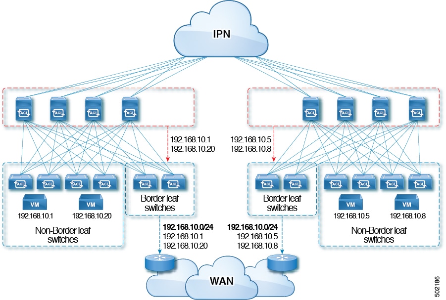
Advertise Host Routes
Enabling Advertise Host Routes on the BD, individual host-routes (/32 and /128 prefixes) are advertised from the Border-Leaf
switches (BL). The BD must be associated to the L3out or an explicit prefix list matching the host routes. The host routes
must be configured to advertise host routes out of the fabric.
Border-Leaf switches along with the subnet advertise the individual end-point(EP) prefixes. The route information is advertised
only if the host is connected to the local POD. If the EP is moved away from the local POD or once the EP is removed from
EP database (even if the EP is attached to a remote leaf), the route advertisement is then withdrawn.
Advertise Host Route configuration guidelines and limitations are:
The
Advertise Host Routes feature is supported on Generation 2 switches or later
(Cisco Nexus N9K switches with "EX", "FX", or "FX2" on the end of the switch
model name or later; for example, N9K-93108TC-EX).
Host route advertisement supports both BD to L3out Association and the explicit route map configurations. We recommend using
explicit route map configuration which allows you greater control in selecting individual or a range of host routes to configure.
EPs/Host routes in SITE-1 will not be advertised out through Border Leafs in other SITEs.
When EPs is aged out or removed from the database, Host routes are withdrawn from the Border Leaf.
When EP is moved across SITEs or PODs, Host routes should be withdrawn from first SITE/POD and advertised in new POD/SITE.
EPs learned on a specific BD, under any of the BD subnets are advertised from the L3out on the border leaf in the same POD.
EPs are advertised out as Host Routes only in the local POD through the Border Leaf.
Host routes are not advertised out from one POD to another POD.
In the case of Remote Leaf, if EPs are locally learned in the Remote Leaf, they are then advertised only through a L3out deployed
in Remote Leaf switches in same POD.
EPs/Host routes in a Remote Leaf are not advertised out through Border Leaf switches in main POD or another POD.
EPs/Host routes in the main POD are not advertised through L3out in Remote Leaf switches of same POD or another POD.
The BD subnet must have the Advertise Externally option enabled.
The BD must be associated to an L3out or the L3out must have explicit route-map configured matching BD subnets.
There must be a contract between the EPG in the specified BD and the External EPG for the L3out.
Note
If there is no contract between the BD/EPG and the External EPG the BD subnet and host routes will not be installed on the
border leaf.
Advertise Host Route is supported for shared services. For example: epg1/BD1 deployed is in VRF-1 and L3out in another VRF-2.
By providing shared contract between EPG and L3out host routes are pulled from one VRF-1 to another VRF-2.
When Advertise Host Route is enabled on BD custom tag cannot be set on BD Subnet using route-map.
When Advertise Host Route is enabled on a BD and the BD is associated with an L3Out, BD subnet is marked public. If there's
a rogue EP present under the BD, that EP is advertised out on L3Out.
Guidelines for Routed Connectivity to Outside Networks
Use the following guidelines when creating and maintaining Layer 3 outside connections.
Topic
Caution or Guideline
L3Out aggregate stats do not support egress drop counters
When accessing the Select Stats window through Tenants > tenant_name > Networking > L3Outs > L3Out_name > Stats, you will see that L3Out aggregate stats do not
support egress drop counters. This is because there is currently no
hardware table in the ASICs that record egress drops from the EPG
VLAN, so stats do not populate these counters. There are only
ingress drops for the EPG VLAN.
Updates through CLI
For Layer 3 external networks created through the API or GUI and
updated through the CLI, protocols need to be enabled globally on
the external network through the API or GUI, and the node profile
for all the participating nodes needs to be added through the API or
GUI before doing any further updates through the CLI.
Loopbacks for Layer 3 networks on same node
When configuring two Layer 3 external networks on the same node, the
loopbacks need to be configured separately for both Layer 3
networks.
Ingress-based policy enforcement
Starting with Cisco APIC release 1.2(1), ingress-based policy enforcement enables defining policy enforcement for Layer 3
Outside (L3Out) traffic for both egress and ingress directions. The default is ingress. During an upgrade to release 1.2(1)
or higher, existing L3Out configurations are set to egress so that the behavior is consistent with the existing configuration.
You do not need any special upgrade sequence. After the upgrade, you change the global property value to ingress. When it
has been changed, the system reprograms the rules and prefix entries. Rules are removed from the egress leaf and installed
on the ingress leaf, if not already present. If not already configured, an Actrl prefix entry is installed on the ingress leaf. Direct server return (DSR), and attribute EPGs require ingress based policy
enforcement. vzAny and taboo contracts ignore ingress based policy enforcement. Transit rules are applied at ingress.
Bridge Domains with L3Outs
A bridge domain in a tenant can contain a public subnet that is advertised through an l3extOut provisioned in the common tenant.
Bridge domain route advertisement For OSPF and EIGRP
When both OSPF and EIGRP are enabled on the same VRF on a node and if the bridge domain subnets are advertised out of one
of the L3Outs, it will also get advertised out of the protocol enabled on the other L3Out.
For OSPF and EIGRP, the bridge domain route advertisement is per VRF and not per L3Out. The same behavior is expected when
multiple OSPF L3Outs (for multiple areas) are enabled on the same VRF and node. In this case, the bridge domain route will
be advertised out of all the areas, if it is enabled on one of them.
BGP Maximum Prefix Limit
Starting with Cisco APIC release 1.2(1x), tenant policies for BGP l3extOut connections can be configured with a maximum prefix limit, that enables monitoring and restricting the number of route prefixes
received from a peer. Once the maximum prefix limit has been exceeded, a log entry is recorded, and further prefixes are rejected.
The connection can be restarted if the count drops below the threshold in a fixed interval, or the connection is shut down.
Only one option can be used at a time. The default setting is a limit of 20,000 prefixes, after which new prefixes are rejected.
When the reject option is deployed, BGP accepts one more prefix beyond the configured limit, before the APIC raises a fault.
MTU
Note
Cisco ACI does not support IP fragmentation. Therefore, when you configure Layer 3 Outside (L3Out) connections to external routers,
or Multi-Pod connections through an Inter-Pod Network (IPN), it is recommended that the interface MTU is set appropriately on both ends
of a link. On some platforms, such as Cisco ACI, Cisco NX-OS, and Cisco IOS, the configurable MTU value does not take into account the Ethernet headers (matching IP MTU, and excluding
the 14-18 Ethernet header size), while other platforms, such as IOS-XR, include the Ethernet header in the configured MTU
value. A configured value of 9000 results in a max IP packet size of 9000 bytes in Cisco ACI, Cisco NX-OS, and Cisco IOS, but results in a max IP packet size of 8986 bytes for an IOS-XR untagged interface.
For the appropriate MTU values for each platform, see the relevant configuration guides.
We highly recommend that you test the MTU using CLI-based commands. For example, on the Cisco NX-OS CLI, use a command such as ping 1.1.1.1 df-bit packet-size 9000 source-interface ethernet 1/1.
QoS for L3Outs
To configure QoS policies for an L3Out and enable the policies to be enforced on the BL switch where the L3Out is located,
use the following guidelines:
The VRF Policy Control Enforcement Direction must be set toEgress.
The VRF Policy Control Enforcement Preference must be set to Enabled.
When configuring the contract that controls communication between the EPGs using the L3Out, include the QoS class or Target
DSCP in the contract or subject of the contract.
ICMP settings
ICMP redirect and ICMP unreachable are disabled by default in Cisco ACI to protect the switch CPU from generating these packets.


 Feedback