Route Control with Route Maps and Route Profiles

This chapter contains the following sections:

Route Control Profile Policies

The ACI fabric also supports the route-map set clauses for the routes that are advertised into and out of the fabric. The route-map set rules are configured with the Route Control Profile policies and the Action Rule Profiles.

ACI supports the following set options:

Table 1. Action Rule Profile Properties (route-map set clauses)

Property

OSPF

EIGRP

BGP

Comments

Set Community

Yes

Supports regular and extended communities.

Set Additional Community

Yes

Supports regular and extended communities.

Route Tag

Yes

Yes

Supported only for BD subnets. Transit prefixes are always assigned the tag 4294967295.

Preference

Yes

Sets BGP local preference.

Metric

Yes

Yes

Sets MED for BGP. Will change the metric for EIGRP but you cannot specify the EIGRP composite metric.

Metric Type

Yes

OSPF Type-1 and OSPF Type-2.

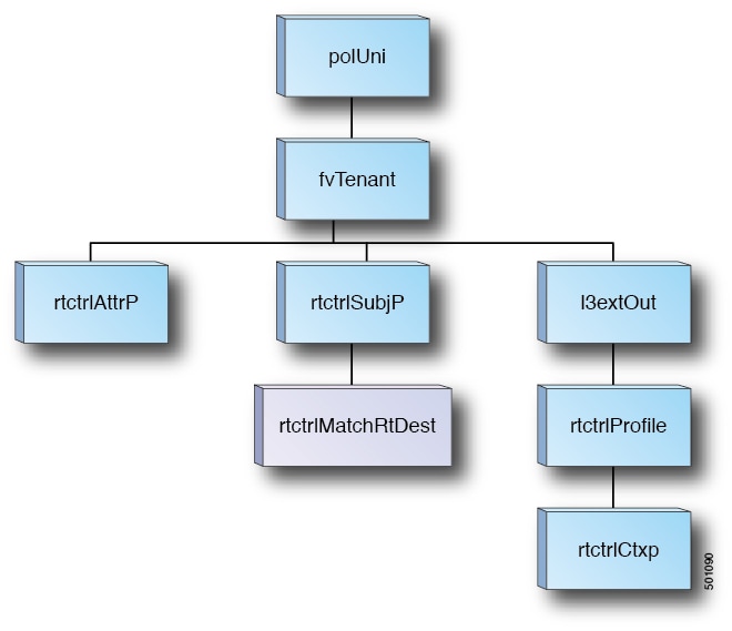
The Route Profile Polices are created under the Layer 3 Outside connection. A Route Control Policy can be referenced by the following objects:

  • Tenant BD Subnet

  • Tenant BD

  • External EPG

  • External EPG import/export subnet

Here is an example of using Import Route Control for BGP and setting the local preference for an external route learned from two different Layer 3 Outsides. The Layer 3 Outside connection for the external connection to AS300 is configured with the Import Route Control enforcement. An action rule profile is configured to set the local preference to 200 in the Action Rule Profile for Local Preference window.

The Layer 3 Outside connection External EPG is configured with a 0.0.0.0/0 import aggregate policy to allow all the routes. This is necessary because the import route control is enforced but any prefixes should not be blocked. The import route control is enforced to allow setting the local preference. Another import subnet 151.0.1.0/24 is added with a Route Profile that references the Action Rule Profile in the External EPG settings for Route Control Profile window.

Use the show ip bgp vrf overlay-1 command to display the MP-BGP table. The MP-BGP table on the spine displays the prefix 151.0.1.0/24 with local preference 200 and a next hop of the border leaf for the BGP 300 Layer 3 Outside connection.

There are two special route control profiles—default-import and default-export. If the user configures using the names default-import and default-export, then the route control profile is automatically applied at the Layer3 outside level for both import and export. The default-import and default-export route control profiles cannot be configured using the 0.0.0.0/0 aggregate.

A route control profile is applied in the following sequential order for fabric routes:

  1. Tenant BD subnet

  2. Tenant BD

  3. Layer3 outside

The route control profile is applied in the following sequential order for transit routes:

  1. External EPG prefix

  2. External EPG

  3. Layer3 outside

About Route Control Per BGP Peer

Route control policies determine what routes are advertised out to the external network (export) or allowed into the fabric (import). For Cisco APIC releases before Release 4.2(1), you configure these policies at the L3Out level, under the L3Out profile (l3extInstP) or through the L3Out subnet under the L3Out (l3extSubnet), so those policies apply to protocols configured for all nodes or paths included in the L3Out. With this configuration, there could be multiple node profiles configured in the L3Out, and each could have multiple nodes or paths with the BGP neighbor specified. Because of this, there is no way to apply individual policies to each protocol entity.

Beginning with Cisco APIC Release 4.2(1), the route control per BGP peer feature is introduced to begin to address this situation, where more granularity in route export and import control is needed.

Guidelines and Restrictions for Route Control Per BGP Peer

Following are the guidelines and restrictions for the route control per BGP peer feature:

  • You must configure route profiles used per BGP peer under a tenant.

  • The methods to configure route map match, set rule or route profile, and the behavior of each of those components, do not change from previous releases.

  • The route profile for this feature can only be set to Match Routing Policy Only (global policy), where the route profile is the only source of information to generate the per BGP peer route map. You cannot set the route profile for this feature to Match Prefix and Routing Policy.

    In addition, you must explicitly specify the BD subnets in the prefix list if you want them to be exported.

  • You can only associate one route-control profile with a BGP peer for a particular direction.

  • Default policy is not supported for these route-maps (only a named route profile can be applied to a BGP peer).

  • If you specify a route-control profile for a BGP peer, then a route-map will be generated solely based on that information. Any route-control profile configured in the L3Out profile (l3extInstP) or through the L3Out subnet under the L3Out (l3extSubnet) will not contribute to this route-map. Similarly, if there is no per BGP peer route-control profile configuration, then the route-control profiles under the L3Out will take effect.

  • If you specify a private BD subnet in the match prefix list, then it will be included. You do not have to go through additional configurations to exclude private BD subnets.

  • If you configure 0.0.0.0/0 in the match prefix list, then it will match all prefixes, including BD subnets.

  • Cisco APIC creates and deploys the route-map on border leaf switches with <tenant name>_<route profile name>_<L3Out name>-<direction>. For example, a route map with these settings:

    • Tenant name: t1

    • Route profile name: rp1

    • L3Out name: l3out1

    • Direction: import

    will have this as the route map name: t1_rp1_l3out1-in

  • Configuring the route control per BGP peer feature should not affect the behavior of the shared service route-map.

  • Keep the following considerations in mind when upgrading or downgrading the APIC software:

    • Upgrading the APIC software: If you configured route profiles in the L3Out before upgrading the APIC software, then the route profiles in the L3Out will continue to behave normally until you configure a per BGP peer route profile, at which point the normal guideline and restrictions listed above would apply.

    • Downgrading the APIC software: If you configure a per BGP peer route profile and you want to downgrade the APIC software afterwards, you must remove the policy before proceeding with the downgrade.

Configuring Route Control Per BGP Peer Using the GUI

The following procedure describes how to configure the route control per BGP peer feature using the GUI.

Before you begin

  • Configure the node, port, functional profile, AEP, and Layer 3 domain.

  • Configure a BGP Route Reflector policy to propagate the routes within the fabric.

Procedure


Step 1

Create the tenant and VRF:

  1. On the menu bar, choose Tenants > Add Tenant.

    The Create Tenant dialog box appears.

  2. In the Name field, enter the tenant name.

  3. In the VRF Name field, enter the VRF name.

  4. Click Submit.

Step 2

Create a bridge domain:

  1. In the Navigation pane, expand Tenant and Networking.

  2. Right-click Bridge Domains and choose Create Bridge Domain.

  3. In the Name field, enter a name for the bridge domain (BD).

  4. (Optional) Click the box for Advertise Host Routes to enable advertisement to all deployed border leafs.

  5. In the VRF field, from the drop-down list, choose the VRF you created (v1 in this example).

  6. Click Next.

  7. Click the + icon on Subnets.

  8. In the Gateway IP field, enter the subnet for the BD.

  9. In the Scope field, choose Advertised Externally.

    Add the L3 Out for Route Profile later, after you create it.

    Note 

    If Advertise Host Routes is enabled, the route-map also matches all host routes.

  10. Click OK.

  11. Click Next and click Finish.

Step 3

Create an application EPG:

  1. Right-click Application Profiles and choose Create Application Profile.

  2. Enter a name for the application.

  3. Click the + icon for EPGs.

  4. Enter a name for the EPG.

  5. From the BD drop-down list, choose the bridge domain you previously created.

  6. Click Update.

  7. Click Submit.

Step 4

Create a tenant level route-map that will be used as the BGP Per Peer Route-Map:

  1. In the Navigation pane, expand the Tenants > Tenant_name > Policies > Protocol.

  2. Right-click on Route Maps for BGP Dampening, Inter-leak and select Create Route Maps for BGP Dampening, Inter-leak.

  3. In the Create Route Maps for BGP Dampening, Inter-leak dialog box, in the Name field, enter a route profile name.

  4. In the Type field, you must choose Match Routing Policy Only.

  5. In the Contexts area, click the + sign to open the Create Route Control Context dialog box and perform the following actions:

    1. Populate the Order and the Name fields as desired.

    2. In the Match Rule field, click Create Match Rule.

    3. In the Create Match Rule dialog box, in the Name field, enter a name for the match rule.

    4. Enter the necessary information in the appropriate fields (Match Regex Community Terms, Match Community Terms and Match Prefix), then click Submit.

    5. In the Set Rule field, click Create Set Rules for a Route Map

    6. In the Create Set Rules for a Route Map dialog box, in the Name field, enter a name for the action rule profile.

    7. Choose the desired attributes, and related community, criteria, tags, and preferences. Click Finish.

    8. In the Create Route Control Context window, click OK.

    9. In the Create Route Maps for BGP Dampening, Inter-leak dialog box, click Submit.

Step 5

Create the L3Out and configure the BGP for the L3Out:

  1. On the Navigation pane, expand Tenant and Networking.

  2. Right-click L3Outs and choose Create L3Out.

  3. Enter the necessary information to configure BGP for the L3Out.

    You will select BGP in the Identity page in the L3Out creation wizard to configure the BGP protocol for this L3Out.
  4. Continue through the remaining pages (Nodes and Interfaces, Protocols, and External EPG) to complete the configuration for the L3Out.

Step 6

After you have completed the L3Out configuration, configure the route control per BGP peer feature:

  1. Navigate to the BGP Peer Connectivity Profile screen:

    Tenants > tenant > Networking > L3Outs > L3out-name > Logical Node Profiles > logical-node-profile-name > Logical Interface Profiles > logical-interface-profile-name > BGP Peer Connectivity Profile IP-address

  2. Scroll down to the Route Control Profile field, then click + to configure the following:

    • Name: Select the route-map that you configured in Step 4.

    • Direction: Choose one of the following options:

      • Route Import Policy

      • Route Export Policy


Route Maps/Profiles with Explicit Prefix Lists

About Route Map/Profile

The route profile is a logical policy that defines an ordered set (rtctrlCtxP) of logical match action rules with associated set action rules. The route profile is the logical abstract of a route map. Multiple route profiles can be merged into a single route map. A route profile can be one of the following types:

  • Match Prefix and Routing Policy: Pervasive subnets (fvSubnet) and external subnets (l3extSubnet) are combined with a route profile and merged into a single route map (or route map entry). Match Prefix and Routing Policy is the default value.

  • Match Routing Policy Only: The route profile is the only source of information to generate a route map, and it will overwrite other policy attributes.


Note

When explicit prefix list is used, the type of the route profile should be set to "match routing policy only".


After the match and set profiles are defined, the route map must be created in the Layer 3 Out. Route maps can be created using one of the following methods:

  • Create a "default-export" route map for export route control, and a "default-import" route map for import route control.

  • Create other route maps (not named default-export or default-import) and setup the relation from one or more l3extInstPs or subnets under the l3extInstP.

  • In either case, match the route map on explicit prefix list by pointing to the rtctrlSubjP within the route map.

In the export and import route map, the set and match rules are grouped together along with the relative sequence across the groups (rtctrlCtxP). Additionally, under each group of match and set statements (rtctrlCtxP) the relation to one or more match profiles are available (rtctrlSubjP).

Any protocol enabled on Layer 3 Out (for example BGP protocol), will use the export and import route map for route filtering.

About Explicit Prefix List Support for Route Maps/Profile

In Cisco APIC, for public bridge domain (BD) subnets and external transit networks, inbound and outbound route controls are provided through an explicit prefix list. Inbound and outbound route control for Layer 3 Out is managed by the route map/profile (rtctrlProfile). The route map/profile policy supports a fully controllable prefix list for Layer 3 Out in the Cisco ACI fabric.

The subnets in the prefix list can represent the bridge domain public subnets or external networks. Explicit prefix list presents an alternate method and can be used instead of the following:

  • Advertising BD subnets through BD to Layer 3 Out relation.


    Note

    The subnet in the BD must be marked public for the subnet to be advertised out.


  • Specifying a subnet in the l3extInstP with export/import route control for advertising transit and external networks.

Explicit prefix list is defined through a new match type that is called match route destination (rtctrlMatchRtDest). An example usage is provided in the API example that follows.

Figure 1. External Policy Model of API

Additional information about match rules, set rules when using explicit prefix list are as follows:

Match Rules

  • Under the tenant (fvTenant), you can create match profiles (rtctrlSubjP) for route map filtering. Each match profile can contain one or more match rules. Match rule supports multiple match types. Prior to Cisco APIC release 2.1(x), match types supported were explicit prefix list and community list.

    Starting with Cisco APIC release 2.1(x), explicit prefix match or match route destination (rtctrlMatchRtDest) is supported.

    Match prefix list (rtctrlMatchRtDest) supports one or more subnets with an optional aggregate flag. Aggregate flags are used for allowing prefix matches with multiple masks starting with the mask mentioned in the configuration till the maximum mask allowed for the address family of the prefix . This is the equivalent of the "le " option in the prefix-list in NX-OS software (example, 10.0.0.0/8 le 32).

    The prefix list can be used for covering the following cases:

    • Allow all ( 0.0.0.0/0 with aggregate flag, equivalent of 0.0.0.0/0 le 32 )

    • One or more of specific prefixes (example: 10.1.1.0/24)

    • One or more of prefixes with aggregate flag (example, equivalent of 10.1.1.0/24 le 32).


    Note

    When a route map with a match prefix “0.0.0.0/0 with aggregate flag” is used under an L3Out EPG in the export direction, the rule is applied only for redistribution from dynamic routing protocols. Therefore, the rule is not applied to the following (in routing protocol such as OSPF or EIGRP):

    • Bridge domain (BD) subnets

    • Directly connected subnets on the border leaf switch

    • Static routes defined on the L3Out


  • The explicit prefix match rules can contain one or more subnets, and these subnets can be bridge domain public subnets or external networks. Subnets can also be aggregated up to the maximum subnet mask (/32 for IPv4 and /128 for IPv6).

  • When multiple match rules of different types are present (such as match community and explicit prefix match), the match rule is allowed only when the match statements of all individual match types match. This is the equivalent of the AND filter. The explicit prefix match is contained by the subject profile (rtctrlSubjP) and will form a logical AND if other match rules are present under the subject profile.

  • Within a given match type (such as match prefix list), at least one of the match rules statement must match. Multiple explicit prefix match (rtctrlMatchRtDest) can be defined under the same subject profile (rtctrlSubjP) which will form a logical OR.

Enhancements for Match Prefix

Starting in Release 4.2(3), two new fields are now available in the Match Prefix field when you are creating a match rule and you enable aggregation:

  • From Prefix (fromPfxLen)

  • To Prefix (toPfxLen)

Use these fields to specify the mask range when you create a prefix match rule and enable aggregation. Following are example situations where you might use these fields:

  • Allow all (0.0.0.0/0 with mask length between 24 to 30, the equivalent of 0.0.0.0/0 ge 24 le 30)

  • Prefixes with a specific IP address and a netmask greater than 28 (for example, the equivalent of 10.1.1.0/24 ge 28)

The following table provides more information on the various scenarios where you might use these two new fields and the result for each scenario. Note the following:

  • The From Prefix and To Prefix fields are available only if you select the Aggregate option in the Create Match Route Destination Rule window.

  • A value of 0 in the From Prefix and To Prefix fields is considered unspecified and assumes the following default values:

    • From Prefix=0

    • To Prefix=32 or 128, depending on whether the IP address family is IPv4 or IPv6.

    This situation assumes legacy behavior and provides support for importing old configurations where these properties are missing. Refer to the second row in the following table for more information.

IP Address/Netmask

Aggregate

From Prefix Entry (fromPfxLen)

To Prefix Entry (toPfxLen)

Result

Additional Information

192.0.2.0/24

Not enabled

N/A

N/A

192.0.2.0/24

Exact match

192.0.2.0/24

Enabled

0

0

192.0.2.0/24 le 32

Legacy behavior

192.0.2.0/24

Enabled

24

Irrelevant value (error occurs because of value provided in From Prefix entry)

ERROR: Invalid configuration.

The From Prefix entry must be larger than the netmask length.

192.0.2.0/24

Enabled

28

30

192.0.2.0/24 ge 28 le 30

New behavior with these new fields

192.0.2.0/24

Enabled

30

0

192.0.2.0/24 ge 30

New behavior with these new fields

192.0.2.0/24

Enabled

28

28

192.0.2.0/24 eq 28

New behavior with these new fields

192.0.2.0/24

Enabled

0

28

192.0.2.0/24 le 28

New behavior with these new fields

192.0.2.0/24

Enabled

30

28

ERROR: Invalid configuration.

The From Prefix entry cannot be larger than the To Prefix entry.

Set Rules

Set policies must be created to define set rules that are carried with the explicit prefixes such as set community and set tag.

Aggregation Support for Explicit Prefix List

Each prefix (rtctrlMatchRtDest) in the match prefixes list can be aggregated to support multiple subnets matching with one prefix list entry.

Aggregated Prefixes and BD Private Subnets

Although subnets in the explicit prefix list match may match the BD private subnets using aggregated or exact match, private subnets will not be advertised through the routing protocol using the explicit prefix list. The scope of the BD subnet must be set to "public" for the explicit prefix list feature to advertise the BD subnets.

Differences in Behavior for 0.0.0.0/0 with Aggregation

The 0.0.0.0/0 with Aggregate configuration creates an IP prefix-list equivalent to “0.0.0.0/0 le 32”. The 0.0.0.0/0 with Aggregate configuration can be used mainly in two situations:

  • “Export Route Control Subnet” with “Aggregate Export” scope in L3Out subnet under the L3Out network (L3Out EPG)

  • An explicit prefix-list (Match Prefix rule) assigned to a route map with the name “default-export”

When used with the “Export Route Control Subnet” scope under the L3Out subnet, the route map will only match routes learned from dynamic routing protocols. It will not match BD subnets or directly-connected networks.

When used with the explicit route map configuration, the route map will match all routes, including BD subnets and directly-connected networks.

Consider the following examples to get a better understanding of the expected and unexpected (inconsistent) behavior in the two situations described above.

Scenario 1

For the first scenario, we configure a route map (with a name of rpm_with_catch_all) using a configuration post similar to the following:


<l3extOut annotation="" descr="" dn="uni/tn-t9/out-L3-out" enforceRtctrl="export" name="L3-out" nameAlias="" ownerKey="" ownerTag="" targetDscp="unspecified">
    <rtctrlProfile annotation="" descr="" name="rpm_with_catch_all" nameAlias="" ownerKey="" ownerTag="" type="combinable">
        <rtctrlCtxP action="permit" annotation="" descr="" name="catch_all" nameAlias="" order="0">
            <rtctrlScope annotation="" descr="" name="" nameAlias="">
                <rtctrlRsScopeToAttrP annotation="" tnRtctrlAttrPName="set_metric_type"/>
            </rtctrlScope>
        </rtctrlCtxP>
    </rtctrlProfile>
    <ospfExtP annotation="" areaCost="1" areaCtrl="redistribute,summary" areaId="backbone" areaType="regular" descr="" multipodInternal="no" nameAlias=""/>
    <l3extRsEctx annotation="" tnFvCtxName="ctx0"/>
    <l3extLNodeP annotation="" configIssues="" descr="" name="leaf" nameAlias="" ownerKey="" ownerTag="" tag="yellow-green" targetDscp="unspecified">
        <l3extRsNodeL3OutAtt annotation="" configIssues="" rtrId="20.2.0.2" rtrIdLoopBack="no" tDn="topology/pod-1/node-104">
            <l3extLoopBackIfP addr="14.1.1.1/32" annotation="" descr="" name="" nameAlias=""/>
            <l3extInfraNodeP annotation="" descr="" fabricExtCtrlPeering="no" fabricExtIntersiteCtrlPeering="no" name="" nameAlias="" spineRole=""/>
        </l3extRsNodeL3OutAtt>
        <l3extLIfP annotation="" descr="" name="interface" nameAlias="" ownerKey="" ownerTag="" tag="yellow-green">
            <ospfIfP annotation="" authKeyId="1" authType="none" descr="" name="" nameAlias="">
                <ospfRsIfPol annotation="" tnOspfIfPolName=""/>
            </ospfIfP>
            <l3extRsPathL3OutAtt addr="36.1.1.1/24" annotation="" autostate="disabled" descr="" encap="vlan-3063" encapScope="local" ifInstT="ext-svi" ipv6Dad="enabled" llAddr="::" mac="00:22:BD:F8:19:FF" mode="regular" mtu="inherit" tDn="topology/pod-1/paths-104/pathep-[accBndlGrp_104_pc13]" targetDscp="unspecified"/>
            <l3extRsNdIfPol annotation="" tnNdIfPolName=""/>
            <l3extRsIngressQosDppPol annotation="" tnQosDppPolName=""/>
            <l3extRsEgressQosDppPol annotation="" tnQosDppPolName=""/>
        </l3extLIfP>
    </l3extLNodeP>
    <l3extInstP annotation="" descr="" exceptionTag="" floodOnEncap="disabled" matchT="AtleastOne" name="epg" nameAlias="" prefGrMemb="exclude" prio="unspecified" targetDscp="unspecified">
        <l3extRsInstPToProfile annotation="" direction="export" tnRtctrlProfileName="rpm_with_catch_all"/>
        <l3extSubnet aggregate="" annotation="" descr="" ip="0.0.0.0/0" name="" nameAlias="" scope="import-security"/>
        <fvRsCustQosPol annotation="" tnQosCustomPolName=""/>
    </l3extInstP>
</l3extOut>


<rtctrlAttrP annotation="" descr="" dn="uni/tn-t9/attr-set_metric_type" name="set_metric_type" nameAlias="">
    <rtctrlSetRtMetricType annotation="" descr="" metricType="ospf-type1" name="" nameAlias="" type="metric-type"/>
</rtctrlAttrP>


<rtctrlSubjP annotation="" descr="" dn="uni/tn-t9/subj-catch_all_ip" name="catch_all_ip" nameAlias="">
    <rtctrlMatchRtDest aggregate="yes" annotation="" descr="" ip="0.0.0.0/0" name="" nameAlias=""/>
</rtctrlSubjP>

With this route map, what we would expect with 0.0.0.0/0 is that all the routes would go with the property metricType="ospf-type1", but only for the OSPF route.

In addition, we also have a subnet configured under a bridge domain (for example, 209.165.201.0/27), with a bridge domain to L3Out relation, using a route map with a pervasive subnet (fvSubnet) for a static route. However, even though the route map shown above is combinable, we do not want it applied for the subnet configured under the bridge domain, because we want 0.0.0.0/0 in the route map above to apply only for the transit route, not on the static route.

Following is the output for the show route-map and show ip prefix-list commands, where exp-ctx-st-2555939 is the name of the outbound route map for the subnet configured under the bridge domain, and the name of the prefix list is provided within the output from the show route-map command:


leaf4# show route-map exp-ctx-st-2555939
route-map exp-ctx-st-2555939, deny, sequence 1 
  Match clauses:
    tag: 4294967295
  Set clauses:
route-map exp-ctx-st-2555939, permit, sequence 15801 
  Match clauses:
    ip address prefix-lists: IPv4-st16391-2555939-exc-int-inferred-export-dst
    ipv6 address prefix-lists: IPv6-deny-all
  Set clauses:

leaf4# show ip prefix-list IPv4-st16391-2555939-exc-int-inferred-export-dst
ip prefix-list IPv4-st16391-2555939-exc-int-inferred-export-dst: 1 entries
   seq 1 permit 209.165.201.0/27 

leaf4# 

In this situation, everything behaves as expected, because when the bridge domain subnet goes out, it is not applying the rpm_with_catch_all route map policies.

Scenario 2

For the second scenario, we configure a "default-export" route map for export route control, where an explicit prefix-list (Match Prefix rule) is assigned to the "default-export" route map, using a configuration post similar to the following:


<l3extOut annotation="" descr="" dn="uni/tn-t9/out-L3-out" enforceRtctrl="export" name="L3-out" nameAlias="" ownerKey="" ownerTag="" targetDscp="unspecified">
    <rtctrlProfile annotation="" descr="" name="default-export" nameAlias="" ownerKey="" ownerTag="" type="combinable">
        <rtctrlCtxP action="permit" annotation="" descr="" name="set-rule" nameAlias="" order="0">
            <rtctrlScope annotation="" descr="" name="" nameAlias="">
                <rtctrlRsScopeToAttrP annotation="" tnRtctrlAttrPName="set_metric_type"/>
            </rtctrlScope>
        </rtctrlCtxP>
    </rtctrlProfile>
    <ospfExtP annotation="" areaCost="1" areaCtrl="redistribute,summary" areaId="backbone" areaType="regular" descr="" multipodInternal="no" nameAlias=""/>
    <l3extRsEctx annotation="" tnFvCtxName="ctx0"/>
    <l3extLNodeP annotation="" configIssues="" descr="" name="leaf" nameAlias="" ownerKey="" ownerTag="" tag="yellow-green" targetDscp="unspecified">
        <l3extRsNodeL3OutAtt annotation="" configIssues="" rtrId="20.2.0.2" rtrIdLoopBack="no" tDn="topology/pod-1/node-104">
            <l3extLoopBackIfP addr="14.1.1.1/32" annotation="" descr="" name="" nameAlias=""/>
            <l3extInfraNodeP annotation="" descr="" fabricExtCtrlPeering="no" fabricExtIntersiteCtrlPeering="no" name="" nameAlias="" spineRole=""/>
        </l3extRsNodeL3OutAtt>
        <l3extLIfP annotation="" descr="" name="interface" nameAlias="" ownerKey="" ownerTag="" tag="yellow-green">
            <ospfIfP annotation="" authKeyId="1" authType="none" descr="" name="" nameAlias="">
                <ospfRsIfPol annotation="" tnOspfIfPolName=""/>
            </ospfIfP>
            <l3extRsPathL3OutAtt addr="36.1.1.1/24" annotation="" autostate="disabled" descr="" encap="vlan-3063" encapScope="local" ifInstT="ext-svi" ipv6Dad="enabled" llAddr="::" mac="00:22:BD:F8:19:FF" mode="regular" mtu="inherit" tDn="topology/pod-1/paths-104/pathep-[accBndlGrp_104_pc13]" targetDscp="unspecified"/>
            <l3extRsNdIfPol annotation="" tnNdIfPolName=""/>
            <l3extRsIngressQosDppPol annotation="" tnQosDppPolName=""/>
            <l3extRsEgressQosDppPol annotation="" tnQosDppPolName=""/>
        </l3extLIfP>
    </l3extLNodeP>
    <l3extInstP annotation="" descr="" exceptionTag="" floodOnEncap="disabled" matchT="AtleastOne" name="epg" nameAlias="" prefGrMemb="exclude" prio="unspecified" targetDscp="unspecified">
        <l3extSubnet aggregate="" annotation="" descr="" ip="0.0.0.0/0" name="" nameAlias="" scope="import-security"/>
        <fvRsCustQosPol annotation="" tnQosCustomPolName=""/>
    </l3extInstP>
</l3extOut>

Notice that this default-export route map has similar information as the rpm_with_catch_all route map, where the IP is set to 0.0.0.0/0 (ip=0.0.0.0/0), and the set rule in the default-export route map is configured only with the Set Metric Type (tnRtctrlAttrPName=set_metric_type).

Similar to the situation in the previous example, we also have the same subnet configured under the bridge domain, with a bridge domain to L3Out relation, as we did in the previous example.

However, following is the output in this scenario for the show route-map and show ip prefix-list commands:


leaf4# show route-map exp-ctx-st-2555939
route-map exp-ctx-st-2555939, deny, sequence 1 
  Match clauses:
    tag: 4294967295
  Set clauses:
route-map exp-ctx-st-2555939, permit, sequence 8201 
  Match clauses:
    ip address prefix-lists: IPv4-st16391-2555939-exc-int-out-default-export2set-rule0pfx-only-dst
    ipv6 address prefix-lists: IPv6-deny-all
  Set clauses:
    metric-type type-1

leaf4# show ip prefix-list IPv4-st16391-2555939-exc-int-inferred-export-dst
% Policy IPv4-st16391-2555939-exc-int-inferred-export-dst not found
ifav82-leaf4# show ip prefix-list IPv4-st16391-2555939-exc-int-out-default-export2set-rule0pfx-only-dst
ip prefix-list IPv4-st16391-2555939-exc-int-out-default-export2set-rule0pfx-only-dst: 1 entries
   seq 1 permit 209.165.201.0/27

leaf4# 

Notice that in this situation, when the bridge domain subnet goes out, it is applying the default-export route map policies. In this situation, that route map matches all routes, including BD subnets and directly-connected networks. This is inconsistent behavior.

Guidelines and Limitations

  • You must choose one of the following two methods to configure your route maps. If you use both methods, it will result in double entries and undefined route maps.

    • Add routes under the bridge domain (BD) and configure a BD to Layer 3 Outside relation

    • Configure the match prefix under rtctrlSubjP match profiles.

  • Starting 2.3(x), deny-static implicit entry has been removed from Export Route Map. The user needs to configure explicitly the permit and deny entries required to control the export of static routes.

  • Route-map per peer in an L3Out is not supported for OSPF and EIGRP. Route-map can only be applied on L3Out as a whole. Starting 4.2(x), route-map per peer in an L3Out is supported for BGP.

    Following are possible workarounds to this issue:

    • Block the prefix from being advertised from the other side of the neighbor.

    • Block the prefix on the route-map on the existing L3Out where you don't want to learn the prefix, and move the neighbor to another L3Out where you want to learn the prefix and create a separate route-map.

  • Creating route-maps using a mixture of GUI and API commands is not supported. As a possible workaround, you can create a route-map different from the default route-map using the GUI, but the route-map created through the GUI on an L3Out cannot be applied to per-peer.

Configuring a Route Map/Profile with Explicit Prefix List Using the GUI

Before you begin

  • Tenant and VRF must be configured.

  • The VRF must be enabled on the leaf switch.

Procedure


Step 1

On the menu bar, click Tenant, and in the Navigation pane, expand Tenant_name > Policies > Protocol > Match Rules.

Step 2

Right click Match Rules, and click Create Match Rule for a Route Map.

Step 3

In the Create Match Rule window, enter a name for the rule and choose the desired community terms.

Step 4

Enter the necessary information for the match prefix.

The method that you use to enter information for the match prefix varies, depending on the APIC release.

  • For APIC releases prior to 4.2(3), in the Create Match Rule window, expand Match Prefix and perform the following actions:

    1. In the IP field, enter the explicit prefix list.

      The explicit prefix can denote a BD subnet or an external network.

    2. (Optional) In the Description field, enter descriptive information about the route destination policy.

    3. Check the Aggregate check box only if you desire an aggregate prefix.

    4. Click Update.

  • For APIC releases 4.2(3) and later, in the Create Match Rule window, click + in the Match Prefix area.

    The Create Match Route Destination Rule window appears. Perform the following actions in this window:

    1. In the IP field, enter the explicit prefix list.

      The explicit prefix can denote a BD subnet or an external network.

    2. (Optional) In the Description field, enter descriptive information about the route destination policy.

    3. Determine if you want an aggregate prefix or not.

      • If you do not want an aggregate prefix, leave the Aggregate unchecked and click Submit, then go to Step 5.

      • If you want an aggregate prefix, check the Aggregate check box.

        The From Prefix and To Prefix fields become available.

        1. In the From Prefix field, specify the prefix length to match.

          The range is from 0 to 128. A value of 0 is considered unspecified.

        2. In the To Prefix field, specify the prefix length to match.

          The range is from 0 to 128. A value of 0 is considered unspecified.

        See Enhancements for Match Prefix for more information on the From Prefix and To Prefix fields for APIC releases 4.2(3) and later.

    4. Click Submit in the Create Match Route Destination Rule window.

Step 5

In the Create Match Rule window, click Submit.

The match rule can have one or more of the match destination rules and one or more match community terms. Across the match types, the AND filter is supported, so all conditions in the match rule must match for the route match rule to be accepted. When there are multiple match prefixes in Match Destination Rules, the OR filter is supported. Any one match prefix is accepted as a route type if it matches.

Step 6

Under L3Outs, click and choose the available default layer 3 out.

If you desire another layer 3 out, you can choose that instead.

Step 7

Right-click Route map for import and export route control, and click Create Route map for import and export route control.

Step 8

In the Create Route map for import and export route control dialog box, use a default route map, or enter a name for the desired route map.

For the purpose of this example, we use default_export route map.

Step 9

In the Type field, choose Match Routing Policy Only.

The Match Routing policy is the global RPC match destination route. The other option in this field is Match Prefix and Routing Policy which is the combinable RPC match destination route.

Step 10

In the Contexts area, expand the + icon to display the Create Route Control Context dialog box.

Step 11

Enter a name for route control context, and choose the desired options for each field. To deny routes that match criteria that are defined in the match rule (which you will be choosing in the next step), select the action deny. The default action is permit.

Step 12

In the Match Rule field, choose the rule that was created earlier.

Step 13

In the Set Rule field, choose Create Set Rules for a Route Map.

Typically in the route map/profile you have a match and so the prefix list is allowed in and out, but in addition some attributes are being set for these routes, so that the routes with the attributes can be matched further.

Step 14

In the Create Set Rules for a Route Map dialog box, enter a name for the action rule and check the desired check boxes. Click Finish.

Step 15

In the Create Route Control Context dialog box, click OK. And in the Create Route map for import and export route control dialog box, click Submit.

This completes the creation of the route map/profile. The route map is a combination of match action rules and set action rules. The route map is associated with export profile or import profile or redistribute profile as desired by the user. You can enable a protocol with the route map.


Routing Control Protocols

About Configuring a Routing Control Protocol Using Import and Export Controls

This topic provides a typical example that shows how to configure a routing control protocol using import and export controls. It assumes that you have configured Layer 3 outside network connections with BGP. You can also perform these tasks for a Layer 3 outside network configured with OSPF.

Configuring a Route Control Protocol to Use Import and Export Controls, With the GUI

This example assumes that you have configured the Layer 3 outside network connections using BGP. It is also possible to perform these tasks for a network configured using OSPF.

This task lists steps to create import and export policies. By default, import controls are not enforced, so the import control must be manually assigned.

Before you begin

  • The tenant, private network, and bridge domain are created.

  • The Layer 3 outside for tenant networks is created.

Procedure


Step 1

On the menu bar, click TENANTS > Tenant_name > Networking > L3Outs > Layer3_Outside_name .

Step 2

Right click Layer3_Outside_name and click Create Route map for import and export route control.

Step 3

In the Create Route map for import and export route control dialog box, perform the following actions:

  1. From the Name field drop-down list, choose the appropriate route profile.

    Depending on your selection, whatever is advertised on the specific outside is automatically used.
  2. In the Type field, choose Match Prefix AND Routing Policy.

  3. In the Contexts area, click + to bring up the Create Route Control Context window.

Step 4

In the Create Route Control Context dialog box, perform the following actions:

  1. In the Order field, choose the desired order number.

  2. In the Name field, enter a name for the route control private network.

  3. From the Match Rule field drop-down list, click Create Match Rule For a Route Map.

  4. In the Create Match Rule dialog box, in the Name field, enter a route match rule name. Click Submit.

    Specify the match community regular expression term and match community terms as desired. Match community factors will require you to specify the name, community and scope.

  5. From the Set Rule drop-down list, choose Create Set Rules For a Route Map.

  6. In the Create Set Rules For a Route Map dialog box, in the Name field, enter a name for the rule.

  7. Check the check boxes for the desired rules you want to set, and choose the appropriate values that are displayed for the choices. Click Finish.

    The policy is created and associated with the action rule.
  8. In the Create Route Control Context window, click OK.

  9. In the Create Route map for import and export route control dialog box, click Submit.

Step 5

In the Navigation pane, choose Route Profile > route_profile_name > route_control_private_network_name .

In the Work pane, under Properties the route profile policy and the associated action rule name are displayed.
Step 6

In the Navigation pane, click the Layer3_Outside_name , then click the Policy/Main tabs.

In the Work pane, the Properties are displayed.
Step 7

(Optional) Next to the Route Control Enforcement field, check the Import check box to enable the import policy.

The import control policy is not enabled by default but can be enabled by the user. The import control policy is supported for BGP and OSPF, but not for EIGRP. If the user enables the import control policy for an unsupported protocol, it will be automatically ignored. The export control policy is supported for BGP, EIGRP, and OSPF.

Note 

If BGP is established over OSPF, then the import control policy is applied only for BGP and ignored for OSPF.

Step 8

To create a customized export policy, right-click Route map for import and export route control, click Create Route map for import and export route control, and perform the following actions:

  1. In the Create Route map for import and export route control dialog box, from the drop-down list in the Name field, choose or enter a name for the export policy.

  2. In the Contexts area, click + to bring up the Create Route Control Context window.

  3. In the Create Route Control Context dialog box, in the Order field, choose a value.

  4. In the Name field, enter a name for the route control private network.

  5. (Optional) From the Match Rule field drop-down list, choose Create Match Rule For a Route Map, and create and attach a match rule policy if desired.

  6. From the Set Rule field drop-down list, choose Create Set Rules For a Route Map and click OK.

    Alternatively, if desired, you can choose an existing set action, and click OK
  7. In the Create Set Rules For A Route Map dialog box, in the Name field, enter a name.

  8. Check the check boxes for the desired rules you want to set, and choose the appropriate values that are displayed for the choices. Click Finish.

    In the Create Route Control Context dialog box, the policy is created and associated with the action rule.
  9. Click OK.

  10. In the Create Route map for import and export route control dialog box, click Submit.

In the Work pane, the export policy is displayed.
Note 
To enable the export policy, it must first be applied. For the purpose of this example, it is applied to all the subnets under the network.
Step 9

In the Navigation pane, expand L3Outs > L3Out_name > External EPGs > externalEPG_name , and perform the following actions:

  1. Expand Route Control Profile.

  2. In the Name field drop-down list, choose the policy created earlier.

  3. In the Direction field drop-down list, choose Route Export Policy. Click Update.


Interleak of External Routes

Overview

This topic provides a typical example of how to configure an interleak of external routes such as OSPF when using Cisco APIC.

Interleak from OSPF has been available in earlier releases. The feature now enables the user to set attributes, such as community, preference, and metric for route leaking from OSPF to BGP.

Configuring Interleak of External Routes Using the GUI

The external routed network configured in the example can also be extended to support IPv4. Both IPv4 and IPv6 routes can be advertised to and learned from the external routed network.

Before you begin

  • The tenant, VRF, and bridge domain are created.

  • The external routed domain is created.

Procedure


Step 1

On the menu bar, click Tenants.

Step 2

In the Navigation pane, expand the Tenant_name > Networking > L3Outs and perform the following actions:

  1. Right-click L3Outs and click Create L3Out.

  2. In the L3Out dialog box, in the Name field, enter a name for the routed outside.

  3. In the VRF field, from the drop-down list, choose the appropriate VRF.

  4. From the L3 Domain drop-down list, choose the appropriate external routed domain.

  5. Check the check box for the desired protocol.

    The options for the purpose of this task are OSPF.

  6. Complete the L3Out configuration using the L3Out wizard.

    Configure the remaining parameters for this L3Out, such as:

    • Associating nodes with the L3Out node profile in the Nodes and Interfaces area

    • Creating an external EPG and creating subnets for that external EPG in the External EPG area

Step 3

After you have completed the configuration of the L3Out, navigate back to the L3Out that you just configured:

Tenants > Tenant_name > Networking > L3Outs > L3Out_name

Step 4

Click the Policy/Main tab to access the Properties window for this L3Out.

Step 5

In the Route Profile for Interleak field, click Create Route Maps for BGP Dampening, Inter-leak.

Step 6

In the Create Route Maps for BGP Dampening, Inter-leak dialog box, in the Name field, enter a route profile name.

Step 7

In the Type field, you must choose Match Routing Policy Only.

Step 8

In the Contexts area, click the + sign to open the Create Route Control Context dialog box and perform the following actions:

  1. Populate the Order and the Name fields as desired.

  2. In the Set Rule field, click Create Set Rules for a Route Map.

  3. In the Create Set Rules for a Route Map dialog box, in the Name field, enter a name for the action rule profile.

  4. Choose the desired attributes, and related community, criteria, tags, and preferences. Click Finish.

  5. In the Create Route Control Context window, click OK.

  6. In the Create Route Maps for BGP Dampening, Inter-leak dialog box, click Submit.

Step 9

In the L3 Outside window, verify that you have this route profile selected in the Route Profile for Interleak field, then click Submit.

The route profile for interleak is created and associated with the L3 Outside.

About Redistribution of Static Routes to BGP With Prefix List

For Cisco APIC releases before Release 4.2(1), you can configure a route map policy for the redistribution of transit routes into BGP using the Create Route Map/Profile feature, which defines the route map for BGP dampening and route redistribution.


Note

The Create Route Map/Profile feature has been renamed to Create Route Maps for BGP Dampening, Interleak in the Cisco APIC 4.2(1) release.


This feature is used to set attributes, such as community, on certain transit routes on one border leaf switch, and then, based on these attributes, configure these routes on other border leaf switches.

Beginning with Cisco APIC Release 4.2(1), this feature is also being extended for static routes. This allows you to configure a route map policy that will be applied while redistributing static routes into BGP.

Configuring the Redistribution of Static Routes to BGP With Prefix List Using the GUI

The following procedure describes how to configure the redistribution of static routes to BGP with prefix list feature using the GUI.

Before you begin

  • Configure the node, port, functional profile, AEP, and Layer 3 domain.

  • Configure a BGP Route Reflector policy to propagate the routes within the fabric.

  • Configure the L3Out.

Procedure


Step 1

Navigate to the L3Out that you just created:

Tenants > tenant > Networking > L3Outs > L3out-name

Step 2

Click the Policy tab for this L3Out to display the Properties page for this L3Out.

Verify that the Main subtab is also selected for this L3Out.

Step 3

Scroll down to the Route Profile for Redistribution field in the L3Out Properties page, then click + to configure the following:

  1. In the Source field, choose static as the source for the route profile for redistribution.

  2. In the Route Map field, choose or create a route map/profile.

    A route profile allows you to set attributes such as community, preference, and metric for route leaking from static.

Step 4

Click Update.


The configuration is complete.