Wiring
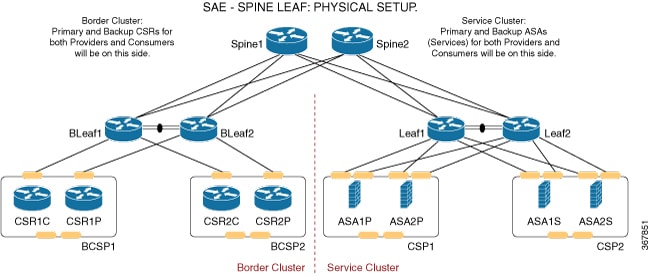
For Acme Corp, it’s proposed that SAE designates two interconnected domains: services and shared-services. The services domain would contain the VNFs and networking of service chains. The services domain is dynamic and capable of scaling out as required.
The shared services domain contains all the services that SAE consumes–NSO, ESC, Firepower Configuration Center (FMC-2500) etc. The shared services domain mainly static and can host SAE-independent platforms.
Hardware Components
| Device | Note |
|---|---|
|
2 x (n) CSP Devices |
|
|
2 x (n) N9K 93180YC-FX leaves |
|
CSP devices support SR-IOV high throughput virtual switching. CSP provides REST APIs and a ConfD interface for managing and creating VNFs and NSO modelled service chains and zones.
Nexus 9000 switches provide the networking fabric for interconnecting VNFs and the physical devices. N9K-C93180YC-FX pairs support Virtual Port Channel (vPC). A vPC can provide Layer 2 multipathing, which allows you to create redundancy by increasing bandwidth, enabling multiple parallel paths between nodes and load-balancing traffic where alternative paths exist.
Recommended Wiring Topology
 Note |
This section details the wiring topology that Cisco recommends. |
Switching Basics
-
Each leaf must be connected to each spine.
-
No spines must be connected to each other.
-
No leaves must be connected to each other, except for the vPC pairs.
Note |
If you don’t order spines, only the leaves would be connected through vPC pairing. |
CSP Devices
Connect the CSP devices as per the topology specified below.
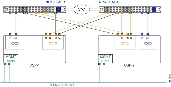
-
Connect each CSP device to both the Nexus 9000 switches using two 10G ports in port-channel configuration. Each CSP device has four XL710 interfaces, which enable port channeling. Two of these ports must be connected to leaf 1 and two to leaf 2.
The figure above shows the formation of two separate port channels. However, you can also form a single aggregate port channel using all four ports on the CSP device.
-
Connect the two X520 interfaces to the switches in a non port-channel configuration.
-
Connect all CSP devices to a separate management L3 network.
This same wiring must be repeated for any new CSP pairs you add to your SAE cluster.
 Feedback