- Preface
- Chapter 1 - Introduction
- Chapter 2 - System Overview
- Chapter 3 - Initial Installation of Connected Lighting
- Chapter 4 - Lighting Migration to Campus Network Architecture
- Chapter 5 - Lighting Deployment without Campus Network Core
- Chapter 6 - Lighting Small Scale Deployment
- Chapter 7 - Lighting Control and Maintenance
- Chapter 8 - Caveats
- Appendix A - References
- Appendix B - Glossary
Lighting Small Scale Deployment
When a lighting solution needs to deploy in a small store/site where 20 or fewer number of light fixtures are required to be installed, a Cisco Catalyst 3850 standalone switch is sufficient, along with SCM, for the lighting network for provisioning light fixtures. In this small scale deployment, a Syslog server can also be connected to the same Cisco Catalyst 3850 switch to manage this small lighting network.
This chapter, which covers the implementation of networking Layer 2, Layer 3, and security features required for a small scale network powered lighting deployment as specified in the Design Guide, includes the following major topics:
Network Topology
In this deployment, one standalone Cisco Catalyst 3850 UPOE is sufficient to implement lighting in a small scale (for example, up to 20 lights in a small retail store) as shown in Figure 6-1.
Figure 6-1 Cisco Digital Building Cree Solution Small Scale Deployment Topology
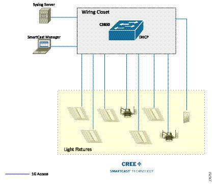
Wiring Closet Access Switch (Cisco Catalyst 3850)
When migrating a lighting initial setup with a Cisco Catalyst 3850 standalone switch for a small scale deployment, SCM is connected directly to the Cisco Catalyst 3850 switch for provisioning light fixtures. Networking Layer 2, Layer 3, and UPOE and security features are also configured on the Cisco Catalyst 3850 switch.
Configuring DHCP Server for Light Fixture IP Addressing
When migrating the initial lighting setup to a small scale deployment, the DHCP server IP addressing pool for light fixtures and wall dimmers is configured on the Cisco Catalyst 3850 switch itself to assign IP addresses to Cree endpoints.
Table 6-1 shows an example DHCP pool range for Cree light fixtures.
Perform the following steps to configure DHCP server pool on Cisco Catalyst 3850/Cisco Catalyst 4506-E switches.
Step 1 Follow Configuring Network Layer 2 and Layer 3 from Steps 1 to 4 in the Wiring Closet Access Switch configuration section in Chapter 4.
Step 2 Configure DHCP server on the Cisco Catalyst 3850 switch. For example:
Configuring Cisco Catalyst 3850 Switch
The configuration of wiring closet access switch in this deployment for UPOE features, security and logging is same as described in Wiring Closet Access Switch (Cisco Catalyst 3850 Stack).
In that section, refer to Configuring UPOE Features, Configuring Security Features, and Configuring Logging (Syslog) to complete the Cisco Catalyst 3850 switch configuration for small scale deployment.
Provisioning Light Fixtures using SmartCast Manager
The light fixtures provisioning steps in this deployment are same as described in Provisioning Light Fixtures (SmartCast Manager), where you can refer to when migrating the lighting initial setup to deployment as shown in Figure 6-1.
 Feedback