- Preface
- Chapter 1 - Introduction
- Chapter 2 - System Overview
- Chapter 3 - Initial Installation of Connected Lighting
- Chapter 4 - Lighting Migration to Campus Network Architecture
- Chapter 5 - Lighting Deployment without Campus Network Core
- Chapter 6 - Lighting Small Scale Deployment
- Chapter 7 - Lighting Control and Maintenance
- Chapter 8 - Caveats
- Appendix A - References
- Appendix B - Glossary
Initial Installation of Connected Lighting
This chapter, which covers implementation details for the initial installation (Day 0) of the Cisco Digital Building Cree Solution, using UPOE switches for the deployment scenarios discussed in the Cisco Digital Building Cree Design Guide, includes the following major topics:
- Initial Installation with Cisco Catalyst 3850 UPOE Switch
- Configuring Cisco Catalyst 3850 UPOE Switch for Initial Installation
- Initial Installation with Cisco Catalyst 4506-E UPOE Switch
- Light Fixture Provisioning for Initial Installation
During the initial installation, the electrician will install the light fixture on wiring closet switches (Cisco Catalyst 3850 or Cisco Catalyst 4506-E) with the default factory configuration to verify the light fixture's operation.
Initial Installation with Cisco Catalyst 3850 UPOE Switch
This section covers network topology and configuration required on Cisco Catalyst 3850 switches for the initial installation of light fixtures.
Network Topology
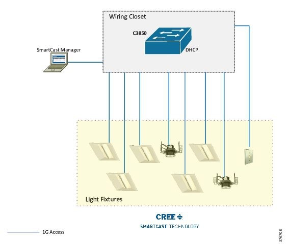
During the initial installation, light fixtures are connected to the wiring closet Cisco Catalyst 3850 UPOE access switch, as shown in the network topology depicted in Figure 3-1.
Figure 3-1 Cisco Digital Building Cree Solution Initial Setup with Cisco Catalyst 3850 Switch
Configuring Cisco Catalyst 3850 UPOE Switch for Initial Installation
Cree Light Fixtures Installation
The initial installation of Cree light fixtures at installation site is generally done by an electrician along with an UPOE switch. The CREE installation, which involves low voltage wiring, does not require an electrical contractor.
When the light fixtures are connected to Cisco Catalyst 3850 UPOE switch ports, the light fixtures turn on with low brightness (~15W of switch port PoE power); this verifies light fixtures' hardware operation by the electrician.
Initial Network Setup
The initial installation of lighting network is generally done by an IT network engineer or the commissioning engineer. Perform the following configuration steps to prepare the lighting network.
Prerequisite for Initial Installation
Complete the following prerequisite step for initial lighting network setup:
- The Cisco Catalyst 3850 switch supports Perpetual and Fast PoE features (described in Chapter 5, “Lighting Deployment without Campus Network Core”) on 3.7.0 EX switch IOS software release. Hence, it is suggested to upgrade the switch IOS image to 3.7.0 EX before beginning lighting network installation.
Step 1 Enable LLDP on the switch global configuration, as shown below. LLDP is required to be enabled on the switch for Cree lights fixtures’ power negotiation. Additionally, static power configuration needs to be enabled per port.
Step 2 Configure SVI for default VLAN 1:
Initial Installation with Cisco Catalyst 4506-E UPOE Switch
This section covers the network topology and configuration required on a Cisco Catalyst 4506-E switch with UPOE line card for the initial installation of light fixtures.
Network Topology
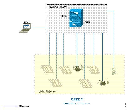
During the initial installation, light fixtures are connected to wiring closet Cisco Catalyst 4506-E UPOE ports, as shown in Figure 3-2.
Figure 3-2 Cisco Digital Building Cree Solution Initial Setup with Cisco Catalyst 4506E Switch
Cree Light Fixtures Installation
The initial installation of Cree light fixtures at an installation site can be done by a low voltage or high voltage electrician. The Cree fixtures will be connected to the Cisco UPOE switch.
When the light fixtures are connected to Cisco Catalyst 4506-E switch UPOE ports, the light fixtures turn on with low brightness (~15W of switch port PoE power); this verifies the light fixtures' hardware operation and connection.
Initial Network Setup
Step 1 Enable LLDP on the switch global configuration, as shown below. LLDP is required to be enabled on the switch for Cree lights fixtures’ power negotiation and operation. Additionally, static power configuration is enabled per port connected to the light fixture.
Step 2 Configure SVI for default VLAN, as shown below:
Light Fixture Provisioning for Initial Installation
This section covers IP addressing using DHCP server and initial commissioning of light fixtures using Cree SCM.
Configuring DHCP Server for Light Fixture IP Addressing
Commissioning the Cree light fixtures for the initial installation verifies the light fixture discovery, calibration, auto-grouping, and wall dimmer operation, using OneButton™ Setup on the Cree SCM application. Light fixtures require IP addresses assigned in the network to perform OneButton Setup for initial provisioning.
During the initial installation, the DHCP server IP addressing pool for light fixtures and wall dimmers is configured on a Cisco Catalyst 3850 or a Cisco Catalyst 4506-E switch to assign IP addresses to Cree endpoints.
Table 3-1 shows an example DHCP pool range for Cree light fixtures.
Configure the DHCP server on a Cisco Catalyst 3850 or a Cisco Catalyst 4506-E switch, where the light fixtures are connected. The following is an example:
Configuring SmartCast Manager for Light Fixture Provisioning
Complete the steps described in this section for installing and configuring Cree SmartCast Manager.
Installing Cree SCM
Refer to Section 3.1, “Installation Procedure” in Cree SmartCast PoE User Manual v1.2.2 for installing Cree SCM.

Note The SCM application connects to the wiring closet switch in the same VLAN as the light fixtures. The switch access port configurations for SCM are similar to light fixture switch port configurations that are discussed in this guide.
Commissioning Light Fixtures
Complete the following steps to provision light fixtures. Refer to Section 3.2, “Walkthrough of the Screens" in the Cree SmartCast PoE User Manual v1.2.2 for detailed step-by-step instructions for provisioning the light fixtures. The following is a summary of the steps:
1. Connect the SCM to an access port on the switch.
2. Launch the SCM application.
3. In the network interface selection, choose the PoE network.
5. Once the devices are listed on the SCM, perform OneButton Setup.
6. Click All to start OneButton Setup.
7. Once the OneButton Setup completes, click Settings. Verify that the Occupancy Group and Switch Group is created.
8. Once OneButton Setup is complete, click All Devices under the Settings tab to verify that all devices in the lighting network are assigned to Occupancy Groups and Switch Groups.
Verifying and Upgrading Light Fixture Firmware
The firmware version of the light fixture can be verified on SCM after it is discovered by SCM. Complete the following steps to check the firmware version of the light fixture on SCM:
Step 1 Navigate to Advanced > Firmware Versions.
Step 2 Choose Lighting Network and then click Show Versions.
Step 3 Verify the version of the Primary, Secondary Firmware, and Firmware Upgrade application. Versions should be Cree endpoints firmware versions contained in the SmartCast PoE v1.2.2 release package.
Note Cree software release package SmartCast PoE v1.2.2 contains SCM v7.3.22, primary firmware v7.4.63, and secondary firmware v1.6.24, which are mapped to top level release packages.
If the light fixtures and wall dimmers are on different firmware versions than the SmartCast PoE v1.2.2 release, upgrading the endpoints to the v1.2.2 release firmware as suggested by Cree is required.
Refer to the Cree Firmware Update section in Cree SmartCast PoE User Manual v1.2.2 for upgrading firmware on Cree endpoints. Also, verify the firmware version after the successful upgrade, by following Steps 1 to 3 above.
 Feedback