- Preface
- Chapter 1 - Introduction
- Chapter 2 - System Overview
- Chapter 3 - Initial Installation of Connected Lighting
- Chapter 4 - Lighting Migration to Campus Network Architecture
- Chapter 5 - Lighting Deployment without Campus Network Core
- Chapter 6 - Lighting Small Scale Deployment
- Chapter 7 - Lighting Control and Maintenance
- Chapter 8 - Caveats
- Appendix A - References
- Appendix B - Glossary
System Overview
This chapter, which provides an overview of the Cisco Digital Building Cree Solution implementation, includes the following major topics:
System Topology
The Cisco Digital Building Cree Solution can be deployed in multiple deployment topologies, based on the customer's requirements and the time when the installation will be done.
Refer to the Cisco Digital Building Cree Design Guide for more details on different deployment topologies.
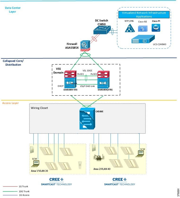
Figure 2-1 and Figure 2-2 show physical network topologies for a large scale lighting network integration with a Campus Network, where wiring closet access switches (Cisco Catalyst 3850 stack or Cisco Catalyst 4506-E) connect to a Campus Network aggregation/distribution switch (Cisco Catalyst 4500-X). In this deployment, the aggregation switch aggregates lighting wiring closet switches and provides IP addressing to light fixtures using DHCP. An aggregation switch in a Campus Network collapsed core/distribution layer connects to the data center via a firewall. The firewall allows only management traffic from the lighting network to flow to the data center.
Figure 2-1and Figure 2-2 show the Cisco Catalyst 3850 switch as an example data center switch for the server farm network access. However, any data center switch as recommended or implemented in the campus data center design, can be leveraged to configure network access to servers.

Note The Campus Network topology shown in Figure 2-1 is one of the deployment models of Campus Network architectures (that is, using a Collapsed Core Network topology) considered for the system design and validation. The detailed implementation of a Campus Network for enterprise network services is beyond the scope of this document. For detailed implementation and best practices for deploying the Campus Network, refer to the Cisco Campus Network CVD at the following URL:
- http://www.cisco.com/c/dam/en/us/td/docs/solutions/CVD/Aug2014/CVD-CampusWiredLANDesignGuide-AUG14.pdf
Figure 2-1 Cisco Digital Building Cree Solution on a Campus Network—Physical Topology with Cisco Catalyst 3850 Stack in Wiring Closet
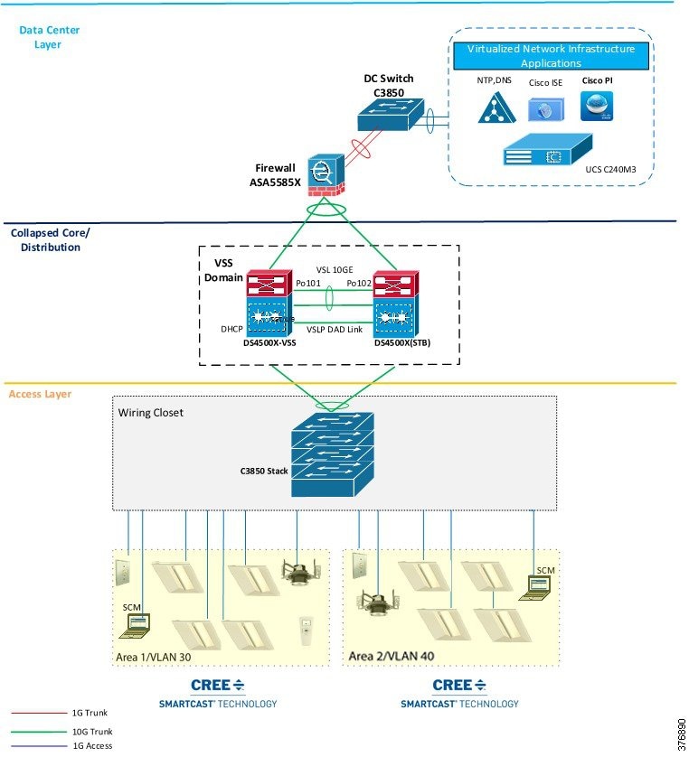
Figure 2-2 Cisco Digital Building Cree Solution on a Campus Network—Physical Topology with Cisco Catalyst 4506E in Wiring Closet
System Components
The components validated within this system consist of a mix of Cisco products (see Table 2-1 ) and Cree products (see Table 2-2 ).
|
|
|
|
|---|---|---|
TACACS+ authentication and authorization server for network devices |
||
Cree will provide the list of commercial names for the following products so that it is in line with the website and the ordering process. See Table 2-2 .
|
|
|
|
|---|---|---|
Table 2-3 is the list of third-party infrastructure components used in the system.
|
|
|
|
|---|---|---|
System Networking
The Digital Building system should deploy on a separate logical network (VLAN) with a limit of 1,000 lights fixtures per VLAN. A new VLAN is required to deploy more than 1,000 light fixtures, which will restrict the number of broadcast messages the light fixtures can process at a time. Each VLAN requires a SmartCast Manager to configure, calibrate and monitor the light fixtures.
This section summarizes the logical network (VLAN) configuration for the Cisco Digital Building Cree Solution network. In Table 2-4 , which lists example implemented VLANs, the subnet mask 255.255.252.0 is used to allow up to 1000 light fixtures per VLAN, as recommended in the Cisco Digital Building Cree Design Guide, Section 4.2.
|
|
|
|
|---|---|---|
VLAN for light fixtures and SmartCast Manager in the data network |
||
VLAN for light fixtures and SmartCast Manager in the data network |
||
Note![]() The VLANs shown in Table 2-4 are only examples that were used in this Cisco Digital Building Cree Solution validation. VLAN numbering may vary based on your actual deployment.
The VLANs shown in Table 2-4 are only examples that were used in this Cisco Digital Building Cree Solution validation. VLAN numbering may vary based on your actual deployment.
 Feedback