Design Details
Virtual Multiservice Data Center (VMDC) functional layers are shown in Figure 2-1.
Figure 2-1 Functional Layers Within the VMDC Data Center
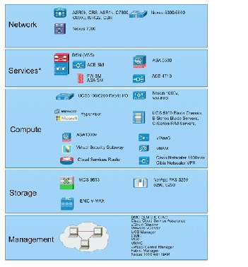

Note Generally, the Services Functional Layer includes physical firewall and server load balancing (SLB) appliance or service module form factors. However, in VMDC VSA 1.0, this layer may comprise virtual appliance form factors.
VMDC Building Blocks
The following functional layers comprise the VMDC component building blocks:
The Network layer includes the WAN/provider edge (PE) router, which forms the data center perimeter to the enterprise area or service provider (SP) IP/NGN backbone, and to the public Internet. These perimeter nodes can be dedicated to Layer 3 (L3) routing functions, or can be multi-service in nature, providing L2 interconnects between data centers along with L3 services. WAN/PE routers validated in the VMDC reference system architecture include: Cisco CRS-1, Cisco ASR 9000, Cisco Catalyst 7600, Catalyst 6500, Cisco ASR 1000, and Cisco ISRG2.
The Network layer includes either a two-layer Clos spine and leaf arrangement of switching nodes, or the traditional two or three-layer hierarchical model described in previous (2.X) releases. While the Virtual Services Architecture (VSA) introduced in VMDC VSA 1.0 works with both models, in this release the Network layer comprises Nexus 9500 systems, serving as core/ aggregation nodes, and Nexus 9300 systems as Top of Rack (TOR) access nodes.
VMDC VSA introduces another network layer functional component, the Cloud Services Router (CSR) which serves as the L3 boundary and logical perimeter for the tenant Virtual Private Cloud container in the multi-tenant/shared cloud data center infrastructure. The CSR is a virtual router, so it resides in the compute tier of the infrastructure. Supporting multiple services, such as IOS zone-based firewalls (ZBFWs), IP security (IPsec) remote access virtual private network (VPN) termination and network address translation (NAT), the CSR provides the flexibility to add additional services without additional CAPEX.
The Services layer comprises network and security services, such as firewalls, SLB, Secure Sockets Layer (SSL) offload, intrusion prevention, network analysis, and gateway functions. A distinct difference arises between the conventional data center services layer and "cloud" data center services layer: the solution set for the latter must support L4 - L7 services at a per-tenant level through logical abstraction of physical resources. Centralized services are most useful in applying policies that are broadly applicable across a range of tenants (or workgroups, in the private case).
In previous VMDC reference architectures (2.X, 3.0), the Data Center Services Node (DSN) provides firewall and SLB services, in a service module form factor (for example, ACE30 and ASA-SM modules). Alternatively, these services are available in appliance form factors (ACE 4710, ASA 5500). This layer also serves as the termination point for remote access IPsec or SSL VPNs. In the VMDC architecture, the Cisco ASA 5580 appliance connected to the aggregation, aggregation-edge switching nodes or the DSN fulfills this function, securing remote tenant access to cloud resources.
In the all-virtual service scenario of VMDC VSA 1.0, these services and more were embedded in the virtual service subsystem of the Compute layer of the infrastructure. Of course, as discussed in VSA 1.0.1, the architecture provides the flexibility to support hybrid physical/virtual service combinations if required for performance or security compliance.
The Compute layer includes three subsystems: virtual access, virtual service, and compute. The first subsystem is a virtual access switching layer, which extends the L2 network across multiple physical compute systems. This virtual access switching layer is key because it also logically extends the L2 network to individual virtual machines (VMs) within physical servers. The feature-rich Cisco Nexus 1000V generally fulfills this role within the architecture. Depending upon the level of software functionality, such as quality of service or security policy or scale required, the Cisco VM Fabric Extender (VM-FEX) can serve as a hardware-based alternative to the Nexus 1000V.
A second subsystem is virtual services (vApp-based), which can include security, SLB, network analysis, and optimization services. Services implemented at this layer of the infrastructure complement more centralized service applications, and uniquely apply to a specific tenant or workgroup and their applications. Specific vApp-based services previously validated for the VMDC architecture include the Cisco Virtual Security Gateway (VSG), providing a second security policy enforcement point within the tenant virtual data center or Virtual Private Cloud container. Additionally, in the VSA system release, IOS-XE ZBF features on the CSR or ASA 1000V may provide perimeter firewalling; the Cisco Netscaler 1000v or Citrix NetScaler VPX provide SLB; the CSR or VPX provide NAT services; the CSR provides IPsec VPN termination; the Virtual Network Analysis Module (vNAM) provides network analysis; and Virtual Wide Area Application Services (vWAAS) provides WAN optimization.
The third subsystem in the Compute layer is the computing resource. This subsystem includes physical servers, hypervisor software providing compute virtualization abilities, and the VMs. The Cisco Unified Computing System (UCS), featuring redundant 6100 or 6200 Fabric Interconnects, UCS 5108 Blade Chassis, and B-Series Blade or C-Series servers, comprise the compute resources in the VMDC reference architecture.
The Storage layer provides storage resources, access and control. Data stores reside in a storage area network (SAN), which is block-based, or in network attached storage (NAS), which is file-based. SAN switching nodes provide resilience, interconnecting multiple SAN storage arrays to the compute resources over redundant FibreChannel or FibreChannel over Ethernet (FCoE) links. For NAS data traffic, the Network Layer design provides a similar level of resiliency.
The Management layer comprises the "back-end" hardware and software resources required to manage the multi-tenant infrastructure. These resources include domain element management systems and higher level service orchestration systems. The domain management systems currently validated within VMDC include Cisco UCS Manager, Cisco Integrated Management Controller, VMware vCenter, and vCloud Director for compute resource allocation; EMC UIM and Cisco Fabric Manager for storage administration; vWAAS Central Manager for traffic optimization services management; and Cisco VSM and Virtual Network Management Center (VNMC) for virtual access and virtual services management. Network Analysis Modules (NAMs), residing within Nexus 1010 systems or as vNAMs within the compute layer of the infrastructure, provide network analysis functionality.
Note Also available and validated as FlexPod domain management components are the NetApp OnCommand Unified Manager and OnCommand System Manager software, NetApp VSC (Virtual Storage Console - a vCenter plug-in that provides end-to-end virtual machine (VM) monitoring, provisioning, B&R and management for VMware vSphere environments running on NetApp storage).
This layer can also include third party NetFlow collectors for aggregating and correlating network statistics. BMC Cloud Lifecycle Management (CLM) or Cisco Intelligent Automation for Cloud (CIAC) provides automated service provisioning, including cross-resource service orchestration. Zenoss Cloud Service Assurance provides "Day 2" service impact visibility and root cause analysis tools. However, service orchestration and assurance solutions were not in scope for this VMDC system release.
PoD
Previous iterations of the VMDC reference architecture defined resource containers called "pods" that serve as the basis for modularity within the Cloud data center (Figure 2-2). As a homogenous modular unit of network, compute, and storage resources, the pod concept addresses environmental, physical, logical, and application-level requirements in a consistent way. The pod serves as a blueprint for incremental build-out of cloud data centers in a structured fashion. When resource utilization within a pod reaches a predetermined threshold (for example, 70% to 80%), the idea is that one simply deploys a new pod. From a service fulfillment and orchestration perspective, a pod represents a discrete resource management domain.
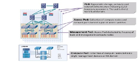
In practice, the pod concept can serve simply as a framework, with designers defining variants tuned to specific environmental or performance characteristics. A pod can be defined at different levels of modularity, supporting growth in differing increments. For example, one could have an access pod, terminating at access switching nodes within an infrastructure; and one could have a compute pod, addressing only the compute or the compute and storage portions of the infrastructure. Special-purpose pods can be defined around application requirements or operational functions. For example, in the VMDC reference architecture, a management pod, called a Virtual Management Infrastructure (VMI) pod, is defined to physically and logically separate back-end management resources from production resources.
Previously in the VMDC reference architecture, a general purpose utility compute pod extended from the compute and storage layers to the L2 ports on aggregation nodes serving as the L2/L3 boundary, up to and including components in the network services layer. This demarcation allowed one to factor in network services in the resource pool, plus the fact that raw port capacity and MAC address scale on the aggregation nodes comprised basic but key growth constraints. However, in the VSA architecture models, the logical topology is modified to move the L3 boundaries to the centralized PE/WAN edge router and the per-tenant virtual CE routers (or distributed per-tenant virtual PE routers) in the compute layer. Similarly, service appliances move from the aggregation layer to the compute layer. In this case, one could consider the L3VPN gateway (physical PE) routers as a pod boundary, in that they essentially serve as a multi-tenant aggregation point, with L3 (route peer) scale a key resource in determining per-pod capacity.
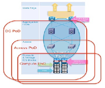
Another option is to define a pod along access switch (leaf node) boundaries. Alternatively, one can define a compute pod, built along UCS system boundaries. In this release, because a tenant footprint is hosted across a number of Compute or Access switching systems, we depict a pod as extending from the compute layer across the entire data center FabricPath domain, up to and including trunks to ports on the PE/WAN edge routers (DC Pod, Figure 2-3).
Figure 2-3 DC Pod in VMDC VSA 1.0
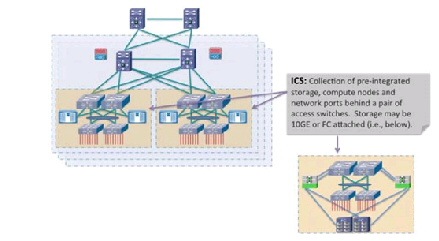
Integrated Compute Stacks
An Integrated Compute Stack (ICS) represents another potential unit of modularity in the VMDC cloud data center, representing a subcomponent within the pod. An ICS is an integrated collection of storage, compute, and network resources, up to and including L2 ports on a pair of access switching nodes. Figure 2-4 shows the location of the ICS in a pod. Multiple ICSs are deployed like building blocks to fill the capacity of a pod. This optimizes flexibility and allows Data Center Operations to incur CAPEX costs on a pay as you grow basis.
Figure 2-4 DC Pod in VMDC VSA 1.0
Working with ecosystem partners, Cisco currently supports two ICS options: Vblock and FlexPod.
- A Vblock comprises Cisco UCS and EMC storage systems, offered in several combinations to meet price, performance, and scale requirements.
- A FlexPod comprises UCS compute and NetApp storage resources. FlexPods are offered in a range of sizes designed to achieve specific workload requirements. A FlexPod can be scaled up or scaled out to host the entire workload for a particular pod. Using a FlexPod at the ICS layer provides the flexibility to scale the ICS layer to a Pod. FlexPods are integrated into ICS by attaching at the FabricPath access-edge nodes (for example, Nexus 5500 or Nexus 7000).
More information about Vblocks and FlexPod implementations is available here: http://ww
w.cisco.com/en/US/netsol/ns1137/index.html
The VMDC reference architecture further accommodates generic compute and storage units, including storage from other third-party vendors. However, the business advantage of an ICS is that integration takes the guesswork out of balancing compute processing power with storage input/output operations per second (IOPS) to meet application performance requirements.
Data Center Interconnect
In the VMDC reference architecture, pods can be interconnected between data centers using various data center interconnection methods, such as Overlay Transport Virtualization (OTV), xPLS, or Locator/ID Separation Protocol (LISP). Though not in scope for VMDC VSA 1.0, these technologies have been tested and the resulting analysis is available in VMDC reference documents, Refer to VMDC DCI 1.0 Design Guide for details.
Unified Data Center Networking
Past descriptions of a unified fabric focused rather narrowly on storage transport technologies, such as FCoE. In a cloud architecture model such as VMDC, the concept of a unified fabric is one of virtualized data center resources (compute, application, storage) connected through a high-bandwidth network that is very scalable, high performing, and enables the convergence of multiple protocols onto a single physical network. In this context, the network is the unified fabric. FCoE, VM-FEX, vPCs and FabricPath are Ethernet technologies that have evolved data center fabric design options. These technologies can be used concurrently over the VMDC Nexus-based infrastructure.
FCoE uses FSPF (Fabric Shortest Path First) forwarding, which FabricPath does not yet support (FabricPath uses an IS-IS control plane). FCoE must be transported on separate (classical Ethernet) VLANs. In VSA, we assume that FCoE links are leveraged outside of the FabricPath domain-such as within the ICS portions of the FabricPath-based pod-to reduce cabling and adapter expenses and to realize power and space savings. It should also be noted that Nexus 9000 systems do not support FCOE or FabricPath as of this writing.
Compute
The VMDC compute architecture assumes, as a baseline premise, a high degree of server virtualization, driven by data center consolidation, the dynamic resource allocation requirements fundamental to a "cloud" model, and the need to maximize operational efficiencies while reducing capital expense (CAPEX). Therefore, the architecture is based upon three key elements:
1.![]() Hypervisor-based Virtualization—In VMDC VSA 1.0, as in previous VMDC releases, VMware vSphere plays a key role, logically abstracting the server environment in terms of CPU, memory, and network into multiple virtual software containers to enable VM creation on physical servers. In this release, vSphere VMs provide the foundation for router and service node virtualization.
Hypervisor-based Virtualization—In VMDC VSA 1.0, as in previous VMDC releases, VMware vSphere plays a key role, logically abstracting the server environment in terms of CPU, memory, and network into multiple virtual software containers to enable VM creation on physical servers. In this release, vSphere VMs provide the foundation for router and service node virtualization.
Note Separate, interrelated documents address Microsoft Hyper-V and Nexus 1000V integration for application workloads in VMDC FabricPath systems: http://www.cisco.com/en/US/docs/solutions/Enterprise/Data_Center/VMDC/Hyper-V/MS_Hyper_V.html
2.![]() UCS Network, Server, and I/O Resources in a Converged System—UCS provides a highly resilient, low-latency unified fabric for integrating lossless 10 Gigabit Ethernet and FCoE functions using x86 server architectures. UCS provides a stateless compute environment that abstracts I/O resources, server personality, configuration, and connectivity to facilitate dynamic programmability. Hardware state abstraction simplifies moving applications and operating systems across server hardware.
UCS Network, Server, and I/O Resources in a Converged System—UCS provides a highly resilient, low-latency unified fabric for integrating lossless 10 Gigabit Ethernet and FCoE functions using x86 server architectures. UCS provides a stateless compute environment that abstracts I/O resources, server personality, configuration, and connectivity to facilitate dynamic programmability. Hardware state abstraction simplifies moving applications and operating systems across server hardware.
3.![]() The Nexus 1000V—This virtual switch, which provides a feature-rich alternative to VMware Distributed Virtual Switch, incorporates software-based VN-link technology to extend network visibility, QoS, and security policy to the VM level. VMDC VSA 1.0 uses VMware vSphere 5.1 as the compute virtualization operating system. A complete list of new vSphere 5.1 enhancements is available
online
. Key "baseline" vSphere features leveraged by the system include ESXi boot from SAN, VMware High Availability (HA), and Distributed Resource Scheduler (DRS). Basic to the virtualized compute architecture is the notion of clusters; a cluster comprises two or more hosts with their associated resource pools, VMs, and data stores. Working with vCenter as a compute domain manager, vSphere advanced functionality, such as HA and DRS, is built around the management of cluster resources. vSphere supports cluster sizes of up to 32 servers when HA or DRS features are used. In practice, however, the larger the scale of the compute environment and the higher the virtualization (VM, network interface, and port) requirements, the more advisable it is to use smaller cluster sizes to optimize performance and virtual interface port scale and limit the intra-cluster failure domain. Previously in VMDC large pod simulations, cluster sizes were limited to eight servers; in smaller pod simulations, cluster sizes of 16 or 32 were used. For VMDC VSA 1.0, cluster sizes of 16 servers are deployed in the system under test (SUT). As in previous VMDC releases, three compute profiles are created to represent large, medium, and small application workloads: “Large” has 1 vCPU/core and 16 GB RAM; “Medium” has 0.5 vCPU/core and 8 GB RAM; and “Small” has 0.25 vCPU/core and 4 GB of RAM.
The Nexus 1000V—This virtual switch, which provides a feature-rich alternative to VMware Distributed Virtual Switch, incorporates software-based VN-link technology to extend network visibility, QoS, and security policy to the VM level. VMDC VSA 1.0 uses VMware vSphere 5.1 as the compute virtualization operating system. A complete list of new vSphere 5.1 enhancements is available
online
. Key "baseline" vSphere features leveraged by the system include ESXi boot from SAN, VMware High Availability (HA), and Distributed Resource Scheduler (DRS). Basic to the virtualized compute architecture is the notion of clusters; a cluster comprises two or more hosts with their associated resource pools, VMs, and data stores. Working with vCenter as a compute domain manager, vSphere advanced functionality, such as HA and DRS, is built around the management of cluster resources. vSphere supports cluster sizes of up to 32 servers when HA or DRS features are used. In practice, however, the larger the scale of the compute environment and the higher the virtualization (VM, network interface, and port) requirements, the more advisable it is to use smaller cluster sizes to optimize performance and virtual interface port scale and limit the intra-cluster failure domain. Previously in VMDC large pod simulations, cluster sizes were limited to eight servers; in smaller pod simulations, cluster sizes of 16 or 32 were used. For VMDC VSA 1.0, cluster sizes of 16 servers are deployed in the system under test (SUT). As in previous VMDC releases, three compute profiles are created to represent large, medium, and small application workloads: “Large” has 1 vCPU/core and 16 GB RAM; “Medium” has 0.5 vCPU/core and 8 GB RAM; and “Small” has 0.25 vCPU/core and 4 GB of RAM.
The Nexus 1000V provides additional logical segmentation capabilities using VXLANs. A MAC-in-UDP encapsulation, VXLAN packets feature a 24-bit LAN segment identifier that significantly increases logical scale in the infrastructure. The Nexus 1000V performs VXLAN encapsulation and de-encapsulation, so VXLANs are transparent to infrastructure layers north of this virtual access edge device.
Finally, the compute layer of the infrastructure can include bare metal servers for applications that are unsuitable for virtualization. For example, in VMDC VSA 1.0, bare metal servers were attached via 1 GE interfaces to FEX 2200s attached to Nexus 5500 or Nexus 7000 access-edge (leaf) nodes. In this release, Nexus 93128TX Top of Rack access nodes provide ninety-six nonblocking ports for direct attachment of bare metal servers at 1 and 10Gbps. Of course, blade servers within the UCS may be provisioned as non-virtualized servers.
The UCS-based compute architecture has the following characteristics:
- It comprises multiple UCS 5100 Series chassis, each populated with eight half-width server blades.
- Each server has dual 10 GigE attachments – in other words, to redundant A and B sides of the internal UCS fabric.
- UCS is a fully redundant system, with two 2200 Series FEX per chassis and two 6200 Series Fabric Interconnects per system.
- Internally, eight uplinks per FEX feed into dual Fabric Interconnects to pre-stage the system for the maximum possible bandwidth per server. This configuration means that each server has 20 GigE bandwidth for server-to-server traffic in the UCS fabric.
- Each UCS 6200 Fabric Interconnect aggregates via redundant 10 GigE EtherChannel connections into the "access-edge" switch (Nexus 9300 in this release). The number of uplinks provisioned will depend upon traffic engineering requirements. For example, to provide an eight-chassis system with an 8:1 oversubscription ratio for internal fabric bandwidth to aggregation-edge bandwidth, a total of 160 Gbps (16 x 10 Gbps) of uplink bandwidth capacity must be provided per UCS system.
- Four ports from an FC GEM in each 6200 Expansion Slot provide 8 Gbps Fibre Channel to Cisco MDS 9513 SAN switches (for example, 6200 chassis A, 4 x 8 Gbps Fibre Channel to MDS A and 6200 chassis B, 4 x 8 Gbps Fibre Channel to MDS B). To maximize IOPS, the aggregate link bandwidth from the UCS to the MDS should match the processing capability of the storage controllers. For Ethernet connectivity to FAS systems vPCs provide redundant active/active (2x10Gbps) paths to each redundant Nexus 5596 switch in the FlexPod ICS. LACP technology also provides redundant 10Gbps FCOE paths to each Nexus 5596 ICS switch.
- The Nexus 1000V functions as the virtual access switching layer, providing per-VM policy and policy mobility.
Storage
The following storage architecture is detailed.
SAN Architecture
The VMDC SAN architecture remains unchanged from previous (2.0 and 3.0) programs. It follows current best practice guidelines for scalability, high availability, and traffic isolation. Key design aspects of the architecture include:
- Leveraging Cisco Data Center Unified Fabric to optimize and reduce LAN and SAN cabling costs.
- HA through multi-level redundancy (link, port, fabric, Director, RAID).
- Risk mitigation through fabric isolation (multiple fabrics, VSANs).
- Data store isolation through n-port virtualization (NPV) and n-port identifier virtualization (NPIV) techniques, combined with zoning and LUN masking.
In terms of VMDC validation, the focus to date has been on storage as a distributed, pod-based resource. This is based on the premise that it is more efficient for performance and traffic flow optimization to locate data store resources as close to the tenant hosts and vApps as possible. In this context, we have the following methods of attaching FibreChannel storage components into the infrastructure as shown in Figure 2-5:
1.![]() Models that follow the ICS model of attachment via Nexus 5000 and Nexus 7000, depending upon ICS type.
Models that follow the ICS model of attachment via Nexus 5000 and Nexus 7000, depending upon ICS type.
2.![]() Models that provide for attachment at the UCS Fabric Interconnect.
Models that provide for attachment at the UCS Fabric Interconnect.
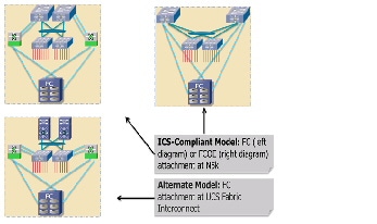
In these scenarios, Cisco's unified fabric capabilities are leveraged with converged network adapters (CNAs) to provide "SAN-ready" servers, and NPV on the UCS Fabric Interconnect or Nexus 5000 top-of-rack (ToR) switches, enabling each aggregated host to be uniquely identified and managed through the fabric and over uplinks to the SAN. Multiple FC links are used from each (redundant) Nexus 5000 or UCS Fabric Interconnect to the MDS SAN switches, to match the current maximum processing capability of the SAN and thus eliminate lack of bandwidth as a potential bottleneck between the SAN components and their point of attachment to the network infrastructure.
Similarly, for FCOE, multiple 10 GigE links provide resilience, and performance and cost efficiencies, by consolidating IP data, file and block traffic onto Ethernet. In this case, additional consolidation for smaller infrastructures may be attained by eliminating SAN switching systems, as illustrated.
Although Figure 2-5 shows a simplified SAN switching topology, it is important to note that if greater SAN port switching capacity is required, the architecture supports (and has been validated with) more complex, two-tier core-edge SAN topologies, as documented in the VMDC 2.0 " Compact Pod Implementation Guide ," and more generally in Cisco SAN switching best practice guides, available at http://www.cisco.com/en/US/prod/collateral/ps4159/ps6409/ps5990/white_paper_C11-515630.html .
NAS Architecture
The VMDC NAS architecture is FlexPod -aligned, following current best practice guidelines for scalability, HA, and traffic isolation. Key design aspects of this portion of the architecture include:
- Infrastructure resiliency through multi-level redundancy of field replaceable unit (FRU) components, multipath HA controller configurations, RAID-DP, and software enhancements that help with failures from a software perspective and a hardware perspective.
- Risk mitigation through fabric isolation and multi-level redundancy of connections (multiple fabrics, vPCs or port-channels, interface groups at the storage layer).
- vPCs address aggregate bandwidth, link, and device resiliency. UCS fabric interconnects and NetApp FAS controllers benefit from the Nexus vPC abstraction, gaining link and device resiliency, and full utilization of a non-blocking Ethernet fabric. From a storage perspective, both standard Link Aggregation Control Protocol (LACP) and the vPC link aggregation technologies play important roles in the FlexPod design.
- Network redundancy in NetApp clustered Data ONTAP is supported by the interconnect and switching fabrics, permitting cluster and data and management network interfaces to fail over to different nodes in the cluster, which extends beyond the HA pair.
For NAS connectivity, the FlexPod architecture leverages the Unified Target Adapter (UTA) and the traditional 10 GigE Ethernet adapter. UTA provides the greatest flexibility when migrating to an end-to-end FCoE design; however, a standard 10 GigE can be used for IP-based storage designs. The vPC links between the Nexus 5548 switches and NetApp storage controller UTAs are converged, supporting both FCoE and traditional Ethernet traffic at 10 Gbps and providing a robust connection between initiator and target. UTAs installed in each NetApp storage controller use FCoE to send and receive Fibre Channel traffic to and from the Nexus switches over 10 GigE. UCS also uses FCoE to send and receive Fibre Channel traffic to and from the various UCS components (for example, UCS B-Series blade servers and UCS C-Series servers). The system provides the option to leverage true end-to-end FCoE, which greatly simplifies network design and reduces application time to market.
Container Models
This section details the following types of containers.
Networking Models
Virtualizing compute and storage resources enables sharing across an organizational entity. In contrast, virtualized multi-tenancy, a concept at the heart of the VMDC reference architecture, refers to the logical isolation of shared virtual compute, storage, and network resources. In essence, this is "bounded" or compartmentalized sharing. A tenant is a user community with some level of common security affinities. For example, in an enterprise, a tenant may be a business unit, department, or workgroup. Depending upon business requirements or regulatory policies, a tenant "container" may stretch across physical boundaries, organizational boundaries, and even between corporations. In large-scale environments, network function virtualization of tenant services provides considerable CAPEX cost savings, enabling a "pay as you grow" infrastructure model.
A tenant container can reside wholly in the private cloud, or can extend from the tenant enterprise to SP facilities in a public cloud. The VMDC architecture addresses these tenancy use cases through a combination of secured data path isolation and a tiered security model that leverages classical security best practices and updates them for the virtualized multitenant environment.
VMDC VSA 1.0.2 considers the following (all virtual) container models:
- Bronze—The most basic container type, a bronze container features a single logical segment for the attachment of hosts. Optionally, an L2 virtual firewall (for example, Cisco VSG) can be applied to provide security zoning. In this container model the CSR provides the L3 boundary, serving as the logical perimeter for this container, and as the default gateway.
- Zinc—A new container in VMDC VSA, the Zinc container is similar to Bronze in that the zinc container is also a single-segment container. However, the logical perimeter and L3 boundary is the ASA 1000V virtual firewall. With only one “outside” and “inside” interface, a common deployment use case is expected to be protecting servers from client traffic originating from the public Internet. Again, the VSG is shown as an optional second L2 policy enforcement point. Additional virtual optimization and network analysis appliances are also options.
- Silver—The silver container expands services, featuring three logical segments and adding SLB. As in any container model, VSG can be added to provide additional zoning. Also, as in the Bronze container, the CSR provides the L3 boundary and default gateway.
- Expanded Gold—This container type is the most complex, providing more expansion of protected front-end and back-end zones while furthering the notion of separating public (Internet or demilitarized zone (DMZ)) or shared (campus/inter-organizational) access from private access. The expanded gold container type can include secured remote IPsec access. Note: the CSR does not support SSL remote access (RA) VPN termination as of this writing. In this case, the term "private" can mean that the virtual data center is routed over the private enterprise WAN or through the public cloud provider's IP/NGN via a private MPLS VPN. In the public cloud scenario, this type of virtual data center linked to the tenant Enterprise via an L2 or L3 MPLS VPN, is commonly termed a virtual private data center (VPDC). Public cloud providers often use MPLS VPNs as transport for hybrid managed cloud services. Such services include IP addressing, security (firewalling, managed DMZ, zoning, and secure remote VPN access), and server resiliency solutions.
Figure 2-9 Expanded Gold Container
It is important to note that because the CSR supports multiple logical interfaces, any virtual containers featuring CSR as the L3 boundary support combined virtual and bare metal hosts, via VLAN stitching, or alternatively, via the VXLAN gateway on the Nexus 1000V.
As previously noted, this incremental VSA release included only all-virtual network services functions in scope; however, in VSA 1.0.1 an alternate Expanded Gold container model provides an example of how the architecture may extend to include physical service appliances as required, in this case with a hybrid physical and virtual tiered firewall implementation in which unique per-tenant virtual contexts on the ASA 5500 serve as the perimeter policy enforcement point, and the CSR provides additional security zones within the tenancy container.
Storage Containers
NetApp clustered Data ONTAP is an inherently multi-tenant storage operating system. It is possible to have a single container that represents the resources of the entire cluster, or multiple containers that are assigned specific subsets of cluster resources. These secure virtual storage containers are known as Storage Virtual Machines, or SVMs. A Storage Virtual Machine contains data volumes and one or more logical interfaces (LIFs) which have unique IP addresses or World Wide Port Names (WWPNs) through which data is accessed by the hosts. Each SVM securely isolates the shared virtualized data storage, and appears as a single dedicated array to its clients. Each SVM has a separate administrator authentication domain and can be managed independently by a SVM administrator. Secure multi-tenancy is provided by network administration and control that is scoped to a particular SVM. Multiple SVMs can coexist in a single cluster without being bound to any node in a cluster. Because it is a secure entity, an SVM is only aware of the resources that have been assigned to it and has no knowledge of other SVMs and their respective resources.
Although SVMs have the potential to use any resource available within the cluster, cluster administrators also have the ability to control exactly to which resources, or class of resources, a tenant would have access. This allows the cluster administrator to implement a tiering strategy whereby different business units, workloads, or customers could be assigned different classes of resources. A small cluster might have a small number of potential tiers, while a large cluster with multiple controller and disk types can support many different tiers. Aggregates of various types can be created: SAS aggregates, SATA aggregates, SSD aggregates, and/or Flash Pool aggregates. Tenant volumes can be provisioned in the appropriate aggregate based on requirements in place at the time of initial creation. If those needs or requirements change at a later time, cluster administrators can nondisruptively relocate the volumes to another aggregate of a different tier. Volumes can be easily moved when tenant storage needs change without impacting the running applications. Workloads can be moved between nodes of differing memory and CPU potential, as well as differing amounts of flash-based cache by using Flash Pools and/or Flash Cache as performance tiers.
For infrastructure Service Providers, multiple SVMs can be deployed to securely allocate storage resources to different tenants and delegate management of those resources without dedicating physical hardware to each tenant, or exposing multiple tenants and their data to one another. Service providers can create tiers of service based on the types of cluster resources that will be made available to the tenant SVM, such as SSD storage, high-performance nodes with Flash Cache™, Gigabit Ethernet (GbE) vs. 4Gb Fibre Channel vs. 8Gb Fibre Channel vs. 10GbE interfaces, and so on. Volumes and LIFs can be nondisruptively reconfigured to use these resources, allowing service providers to maintain high availability for their customers. Storage QoS also allows providers to control the data throughput allocated to each tenant. With Storage QoS policies in place, tenants can share the same physical nodes of a cluster without one tenant consuming an unfair share of the node's resources.
Each SVM operates as a separate and distinct entity with its own security domain. Tenants may manage the resources allocated to them through a delegated SVM administration account. Each SVM may connect to unique authentication zones such as Active Directory®, LDAP, or NIS. When using delegation, cluster administrators specify which back-end storage resources (aggregates) the SVM is able to use, and configuration options with the potential to affect other tenants, such as logical interfaces, can only be modified by the cluster administrator. From a performance perspective, maximum IOPS and throughput levels can be set per SVM using quality of service (QoS) policy groups. This allows the cluster administrator to quantify the performance capabilities allocated to each SVM.
For truly secure multi-tenancy, network and fabric configuration must also ensure that tenants are properly isolated from one another. Although it might be desirable for SVMs in an enterprise context to share a common IP network, SVMs used by individual tenants within a shared infrastructure environment should not share IP networks and should remain separated. Both of these goals can be accomplished through the use of VLANs and routing groups with the SVM configuration. From a Fibre Channel perspective, each SVM will have its own unique World Wide Node Name (WWNN) and World Wide Port Names (WWPNs) that are presented to the storage fabric, allowing for granular zoning and fabric security in addition to the array-based LUN masking using initiator groups (igroups). In cases where SVM management has been delegated to the tenant, firewall policies can be enforced at the SVM layer to ensure that only designated IP addresses or subnets can be used for administrative access.
Several tenancy models, characterized by differing applications of NetApp SVMs are described below:
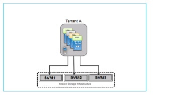
1.![]() Multiple tenants sharing an SVM (Figure 2-10).
Multiple tenants sharing an SVM (Figure 2-10).
A many-to-one mapping between tenants and SVMs is often the most efficient and scalable model for tenant use cases where each may only need relatively small amounts of storage, do not require self-management, and do not require the level of secure data isolation provided by a dedicated SVM. In this model, the storage is effectively abstracted by the hypervisor, which also governs security. This model features relatively limited fault isolation for tenants.
Figure 2-10 Multiple Tenants Sharing an SVM
2.![]() Many tenants mapped to multiple SVMs (Figure 2-11).
Many tenants mapped to multiple SVMs (Figure 2-11).
A many-to-many mapping between tenants and SVMs is an extension of the one-to-many mapping where the isolation and security functionality of individual SVMs are not required, but there may be advantages using different SVMs. Advantages of this model include a high degree of flexibility; the ability for tenants to span clusters and data center; plus the ability to segment service offerings by SVM for fault isolation. Some disadvantages to consider are that this model is more complex and thus more challenging to build and maintain; and the storage is abstracted by the hypervisor, disallowing direct tenant administrative access to storage per VM.
Figure 2-11 Many Tenants Mapped to Multiple SVMs
3.![]() Dedicated 1:1 mapping of tenants to SVMs (Figure 2-12).
Dedicated 1:1 mapping of tenants to SVMs (Figure 2-12).
One-to-one mapping between tenants and SVMs provides the most granular level of control and containment, but does introduce additional design factors around management and scalability. In this model, each tenant is securely isolated at multiple layers of the storage stack: from the storage access point (via IP addresses and VLANs for NAS and/or iSCSI, or WWNNs and WWPNs for FC/FCoE), to the backing volumes and LUNs, to the management of the storage itself. Even the administration of the storage can be securely delegated to the tenant, including integration with the tenant's directory services. Other advantages of this model include a high degree of flexibility in terms of applying storage QoS (per tenant or service level category) and in the application of DR policies per tenant.
Note This model, by definition, allows direct tenant access to storage from VMs.
Dedicating an SVM per tenant for all tenants will not scale in very large environments, as the number of SVMs supported per cluster is limited (e.g., 250 with SAN storage as of this writing for this version of clustered Data ONTAP). SVM scale is dependent on factors such as the number of controllers in the storage cluster, the number of physical ports on each controller and the version of Data ONTAP.
Figure 2-12 Dedicated 1:1 Mapping of Tenants to SVMs
4.![]() One tenant with multiple SVMs (Figure 2-13).
One tenant with multiple SVMs (Figure 2-13).
A one-to-many mapping between a tenant and multiple SVMs can provide larger tenants a secure and flexible allocation of storage resources for multiple groups or business units within their organization. These individual SVMs may be mapped to directly to the internal groups for their own self-management, or provide shared resources for multiple internal groups.
For service providers, the flexibility provided by clustered Data ONTAP's Storage Virtual Machines allows for the implementation of multiple container models tailored to customer application security and availability requirements. As the business needs of a tenant change, the storage resources provided to them can be changed on-the-fly and without disruption to their normal business operations.
Additional information on implementing secure customer separation within a FlexPod unit can be found at:
https://tech.netapp.com/internal/03/technet_services_solutions_smt.html
http://www.netapp.com/us/media/tr-4160.pdf
Figure 2-13 One Tenant with Multiple SVMs
Extending VSA 1.0 Tenancy Models to Storage
The VSA 1.0.1 release leveraged Data ONTAP's SVMs in the following ways to achieve a mapping of tenant network containers to storage containers:
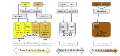
- Three Service Tiers (Gold, Silver, Bronze) were defined.
- The Gold Tier comprised "Gold" tenants, who were each allocated a dedicated SVM for one datastore, the premise being that workloads requiring greater security and isolation would be placed in these SVMs. Gold tenants also shared a common SVM, for other workloads.
- Silver tenants share an SVM. Each tenant in this category has two datastores (on two LUNs), in one volume. FlashCache was enabled on Silver volume types.
- Bronze tenants share an SVM and common datastore, with the number of LUNs scaled to handle all Bronze tenants. FlashCache was disabled on Bronze volume types.
- Additional characteristics that may be employed to profile a storage service level category include—disk size per VM; disk type (FC, SATA, flash); data protection (for example, NetApp SnapVault to provide logical copies at remote sites, Snapshot for virtual copies at local sites); and disaster recovery capabilities (i.e., remote replication at either a LUN or file level of granularity).
These models are illustrated in Figure 2-14.
Figure 2-14 Tenant Containers to NetApp Storage Virtual Machines
Network
Network considerations are detailed in the following sections:
Centralized PE to Distributed Virtual CE Model
A combination of dynamic and static routing is used to communicate reachability information across the L3 portions of the Data Center infrastructure. In this design, dynamic routing is achieved using External Border Gateway Protocol (eBGP) from dedicated, per-tenant virtual routers (CSRs) functioning as vCE routers to redundant, centralized routers (ASR 9000s or ASR 1000s) functioning as PE routers. In cases where ASR1000s are the WAN Edge/PE routers, MED and Local Preference attributes are used to effectively spread inbound and outbound tenant traffic across redundant router pairs.
Note: static routes could alternatively be configured for the vCE to PE paths. This may be an acceptable alternative from an operational standpoint if the routes will be configured using automation systems; otherwise manually maintaining static routes could present a challenge in highly scaled environments.
Depending upon the virtual private cloud container model, the CSR has either one (for example, Bronze, Silver) or two (for example, Expanded Gold) northbound interfaces to the PE router: one connects to the tenant private VRF and the second connects to the PE global routing table for routing over the Internet. Because the CSR supports IPsec VPN termination, encrypted IPsec client traffic from the Internet can be routed via the PE router to the CSR, where it is decrypted and routed to destination hosts in the container. For Zinc containers, in which the ASA 1000V is the logical L3 perimeter, static routes communicate reachability from and to the PE routers. In this model, WAN edge/PE routers effectively function as an L3 autonomous system boundary router (ASBR) and MPLS VPN gateway, extending the tenant virtual private cloud container in the public provider Data Center to their IP VPN.
The CSR1000V and ASA1000V are default gateways for all Hosts and routable virtual service appliances within the tenant containers. The ASR 1000 WAN/PE (or ASR9000 as in VSA 1.0) is the gateway to the Internet and private customer networks, for all devices in the data center. For the ASA 1000V in the Zinc container, the ASR1000 is the default gateway to the Internet, via static routing. For the CSR1000V in Silver/Bronze/Gold containers the ASR1000 is the gateway to the customer networks, which the ASR1000 advertises to the CSR1000v via eBGP. The ASR1000 can inject specific prefixes via BGP to the CSR for more granular control of tenant routing. For the CSR1000V in a Gold container with Internet access, the ASR1000 is the Internet gateway, and advertises a default route to the CSR1000V via eBGP on the Internet-facing link. The CSR does not have to learn all Internet routes, but can simply route traffic destined to the Internet toward the default route. Tenant-to-tenant communication may be enabled through leaking of VRF routes at the centralized PE.
Alternative Logical L3 Models
Alternative L3 logical models for addressing tenancy scale not addressed in this incremental system release include but are not limited to:
1.![]() Implementing MPLS Inter-AS Option B at the aggregation switching nodes, functioning as intra-DC PEs in a traditional hierarchical DC design.
Implementing MPLS Inter-AS Option B at the aggregation switching nodes, functioning as intra-DC PEs in a traditional hierarchical DC design.
2.![]() A distributed Virtual PE (vPE) model, described in
BGP L3VPN Virtual PE Framework
.
A distributed Virtual PE (vPE) model, described in
BGP L3VPN Virtual PE Framework
.
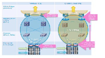
However, the second of these options, the distributed Virtual PE model, is discussed as an alternative VSA logical model in VSA 1.0.1. Briefly, in this model, MPLS is extended to the CSR, functioning in this case as a dedicated, single-tenant Provider Edge router (Figure 2-15). Furthermore, with an additional pair of intra-DC routers functioning as Autonomous System Border Routers (ASBRs)—redundant ASR1000s in our example, the Data Center core can be logically isolated from the backbone, with its own unique Autonomous System representing a separate administrative domain under the management of the Data Center Operations team. Another use case facilitated by this type of logical model is that of a remotely managed private Enterprise cloud, where the intra-DC ASBRs are effectively Cloud Edge Routers for the managed private cloud, with back-end management VLANs for this part of the infrastructure routed via an Extranet set of VPNs to the Service Provider data center for administration.
It is important to note that the vCE and vPE models are not necessarily mutually exclusive - it is possible that a Provider might run both models within a Data Center, depending upon the WAN backbone characteristics, to meet the differing needs of their customers. A practical use case which might lead a Provider to implement a vPE model over a vCE model is one in which the customer or "tenant" requires sub-tenancy—for example, the customer might be an ISV (Independent Software Vendor), and wish to use their slice of the Cloud to provide granular, differentiated services to their customers. Other practical deployment considerations include operational consistency and ease of use: for some, implementing a vCE model might be the simplest and thus more desirable approach; for others, implementing a vPE model may be a more familiar, and thus easier to operate approach.
Figure 2-15 vPE and vCE Models
Layer 2 Design
As previously noted, the VSA architecture may function over a traditional classical Ethernet layer 2 fabric or over a Clos type model utilizing enhanced IS-IS forwarding, such as FabricPath (for example). VSA 1.0 and 1.0.1 in fact were based on the latter option. In this release we consider the use of a classical Ethernet fabric for transport of transit VLANs from the per-tenant CSRs to the centralized WAN Edge/PE routers.
The L2 fabric design relies on extensive use of virtual port channels (vPCs) to eliminate layer 2 loops in the infrastructure from the ICS up through the access and aggregation/core layers and at the WAN Edge/PE router L2 10GE interfaces supporting links connecting to the downstream Nexus 9500 aggregation/core switches (Figure II-1 reference Figure 1-5: VMDC VSA 1.0.2 Intra-DC Topology). Based on LACP technology, vPCs are essentially special types of Ether Channels, with a single device (port) on one end and two sets of devices (and ports) at the other. Since vPCs eliminate loops by making redundant uplinks look like a single logical link, this greatly reduces reliance on Spanning Tree Protocol for loop avoidance. Also, if one link of a vPC goes down, there is no topology change, and so no need for an STP recalculation, with the attendant flooding and traffic interruption that occurs as a result. Between the redundant pair of 9508 core/aggregation switches and pairs of 9300 access switches, back-to-back vPCs, also known as "multi-layer" vPCs, provide a single non-blocking 320G fabric (i.e., 8 x 40G, between 2 sets of paired switches). For this multi-layer vPC deployment mode, each pair of switches interconnected by a vPC peer-link must comprise a single, unique vPC domain, identified as such by a unique domain ID. Thus for example, the 9508s are in vPC domain 1 while a single pair of 9300s are in vPC domain 10. In effect, this insures that each pair of vPC peers looks like a single device, utilizing the same system MAC address for LACP LAGID and STP BPDU Bridge ID generation in order to insure proper operation of LACP and STP.
Multiple Spanning Tree Protocol (MST) prevents the inadvertent creation of loops across the layer 2 topology. MST is recommended over other spanning tree protocol options for any Nexus 9000 L2 design featuring greater than 500 VLANs. In this case the layer 2 domain comprises a single MST instance, though the technology allows for configuration of multiple instances if required. In this design the logical choice is to set the MST roots as the (9508) aggregation/core nodes, as they have the most direct connectivity across the span of access-edge nodes. Further, in order to prevent STP recalculations in the event of the loss of a vPC peer node and optimize reconvergence, the 9508s are configured as vPC peer-switch nodes. By definition, vPC peer-switch nodes function as spanning tree roots and must be configured with the same priority (i.e., appearing to be a single logical root) for proper calculation of the MST tree. Should a root fail, the switch with the next highest priority takes over as root.
Additional key design aspects of the Ethernet layer 2 portion of the design as deployed in this release are summarized below:
- Two core/aggregation nodes, aggregating multiple top of rack access-edge nodes (i.e., mirroring commonly-deployed hierarchical DC topologies).
- Access-edge switches and core/aggregation nodes provide pure layer two functions, providing transit VLANs for vCE to WAN Edge/PE connectivity. This is in contrast to the FabricPath models as implemented in VMDC 3.0-3.0.1, where the Spine nodes performed routing functions or similarly, in traditional hierarchical Ethernet models (i.e., as in VMDC 2.X releases), where the aggregation nodes serve as the L2/L3 boundary.
- The core/aggregation nodes also provide bridging for East/West intra-VLAN traffic flows.
- L2 resilience design options in this infrastructure layer comprise using virtual port-channels between core/aggregation and access-edge nodes across the layer core; and vPCs or Ether Channels on edge nodes for the following options:
1. Attaching UCS servers in end-host mode with vPCs
2. Attaching other Ethernet Switches in vPC mode
3. Attaching rack-mount servers in active/active mode with LACP
4. Direct (1:1) connection of FEX 2200s to upstream 9300 access-edge switches with LACP Ether Channels
- UDLD, rather than LACP, must be used on port channel interfaces from the ASR1000 DC PE to the Layer 2 aggregation layer Nexus 9500 switches, in order to support edge QOS configuration on ASR1000 port channel sub-interfaces.
As of this writing the Nexus 9508 supports three types of I/O modules
1. N9K-X9636PQ (NX-OS 6.1(2)I1(1))—a 36 port, 40G aggregation line card. The 40G interface ports on this module support 10G connectivity with the use of a quad breakout cable (i.e., to 4 x 10GBASE-CU SFP+).
Note Mixing of native 40G and 40G Quad breakouts on the same module is not supported as of this writing.
2. N9K-X9564TX (NX-OS 6.1(2)I2(1))—a 48 port, 1/10G-T plus 4 port QSFP linecard, and the
3. N9K-X9564PX (NX-OS 6.1(2)I2(1))—a 48 port, 1/10G SFP+ plus 4 port QSFP linecard.
These can all be used in standalone NX-OS mode for L2 and L3 forwarding. Only the 9564 models are ACI (leaf)-ready.
With respect to access-edge nodes, the Nexus 9396s with FEX 2232s or 2248s for port expansion or 93128 nodes provide TOR access. Traffic oversubscription can be greatly impacted with increased FEX usage. Alternatively, Nexus 9596s can perform this function, for end-of-row (EOR) access.
Currently, 6200 Series Fabric Interconnects connect to Nexus 9300 access-edge nodes using vPC host mode (vPC-HM).
Virtualization Techniques
Previous program releases leveraged VMware vSphere 5.0, 4.0 and 4.1. vSphere 5.1 is the tenant hypervisor resource used in VMDC VSA 1.X releases. This integrates with Cisco's Nexus 1000V distributed virtual switch, enabling end-to-end visibility to the hypervisor level for security, prioritization, and virtual services.
Though not in scope for VMDC VSA 1.0.2, alternate hypervisors can be used in VMDC reference architectures if UCS is in their prospective Hardware Compatibility List. As of this writing, the Nexus 1000V distributed virtual switch supports only vSphere and Hyper-V. However, alternate hypervisor VMs can connect at the FEX or primary access layer, and participate in appliance-based or Data Center Services Node (DSN) module-based services.
Services
Previous VMDC releases incorporated physical appliance-based and DSN module-based services, and virtual service appliance form factors. From VMDC 2.2 forward, two tiers of security policy enforcement points are featured in the enterprise-grade Expanded Gold container: the first perimeter firewall implemented on a physical form factor, and the second (VSG) implemented as a virtual appliance. The premise was that this hybrid model would best satisfy rigorous security requirements. As is traditional, with the exception of the VMDC 3.0 “Switched Data Center” FabricPath topology model, all physical form factors were attached at the aggregation or aggregation-edge nodes.
VMDC VSA 1.0 departs from tradition in that all IaaS network service functions are virtualized. In this model, services are attached via VLAN stitching at the virtual access edge in the compute layer of the infrastructure. The list of virtual service appliances includes: CSR; Citrix NetScaler VPX, or Cisco Netscaler 1000v for SLB; ASA 1000V; VSG; Virtual Network Analysis Module (vNAM); and the Virtual WAN Acceleration Service Module (vWAAS). Running on general-purpose server hardware, these software-based form factors are ideal for cloud data centers in that they are software-defined and provide flexibility and agility through enhanced programmability.
CSR
Discussed at length in an earlier white paper (VMDC Virtual Service Architecture with CSR), the CSR is an x86-based virtual router based on the ASR 1000 product family. Although the ASR 1000 features optimized ASIC-based forwarding, CSR forwarding is software- based. However, the CSR is extremely feature-rich, inheriting much of the ASR 1000 functionality as it leverages IOS-XE (XE3.10 as of this writing). CSR currently offers a maximum forwarding rate of 1 Gbps, and fixed licensing packages presently rate-limit performance to the following throughput options: 250 Mbps, 100 Mbps, 50 Mbps, 25 Mbps, and 10 Mbps. These packages position CSR as the virtual private Cloud perimeter router solution, where routing throughput requirements generally range from 10Mbps to 1Gbps. As of XE3.10, for the 50 Mbps throughput option, resources required to host the CSR are: 1 vCPU, 2.5G RAM, 8G HD. Note: process-intensive functions may require additional DRAM. Check the release notes for more detailed considerations: http://www.cisco.com/en/US/products/ps12559/prod_release_notes_list.html
The CSR can provide the following services in the VMDC VSA architecture:
Virtual Routing—The CSR is implemented in this release as a virtual CE for routing tenant traffic to the Internet or the tenant IP MPLS VPN via the PE L3 gateway. The CSR routes IPv4 and IPv6 packets and is also the L3 (default) gateway for hosts in the logical virtual private cloud container.
It is important to note that the CSR supports full MPLS functionality. The CSR provides the flexibility to support alternative logical models for scaling multi-tenancy, such as the single-tenant virtual PE model previously validated in VSA 1.0.1.
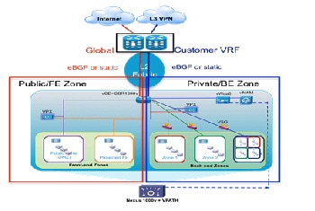
IOS XE ZBF (Zone Based Firewall)—Collapsing perimeter firewall policy enforcement onto the virtual router appliance provides the opportunity to simplify the virtual private cloud container, reducing CAPEX and OPEX costs. Stateful ZBFs are implemented on logical interfaces (Figure 2-16). By default, only interfaces belonging to the same zone can communicate. Zone pairs must be defined to enable inter-zone communication. ZBFs are supported for IPv4 and IPv6 packets. The vCE model facilitates this use case; fine-grained firewalling is possible because the CSR routes only IP-encapsulated packets. In this example, CSR implements a front-end zone, including all applicable downstream and upstream logical segments, to securely separate public and Internet traffic from devices and logical segments participating in the private, back-end zone.
Figure 2-16 Public and Private IOS Zone-Based Firewall on CSR
IPsec VPN gateway—CSR provides route-based IPsec VPNs, terminating and decrypting IPsec VPN tunnels for secure remote access to resources in the virtual private cloud container via the Internet.
Traffic control and visibility point—CSR provides instrumentation for high-touch application visibility and control with features such as Performance Agent for round-trip response time statistics collection, AppNav traffic redirection (for example, to performance optimization service appliances), Switched Port Analyzer (SPAN), NetFlow, QoS, NAT and Dynamic Host Configuration Protocol (DHCP).
Should redundant CSRs be required, Hot Standby Router Protocol (HSRP) can be used to provide resiliency between CSR pairs. In this case, it is actually the HSRP VIP interface that would be the default gateway for hosts within the container. HSRP route tracking can be defined to insure symmetric traffic flows through each CSR.
Server Load Balancer
The Citrix NetScaler VPX, or the Cisco Netscaler 1000v, virtual appliances perform SLB and SSL offload services in the VMDC VSA architecture. As of this writing, the VPX is available in four models, ranging from 200 Mbps to 3 Gbps maximum throughput, suiting a broad range of performance requirements and use cases. This release leverages the 200 Mbps (VPX-200) model. Supported hypervisors as of this writing are: vSphere ESXi, Microsoft Hyper-V, and XenServer. This release is based on the vSphere ESXi hypervisor. The number of logical network interfaces supported by the VPX is determined by hypervisor limits. Currently, for vSphere 5.1 and ESXi hardware version VMX-09, this is a maximum of 10. The VPX supports IPv4 and IPv6 packets, and can operate in transparent or routed mode. Required VPX-200 resources are two vCPUs, 2 GB RAM, and 20 GB HD.
Note The Cisco Netscaler 1000v is an alternative to the Citrix Netscaler VPX. Also available in a variety of license bundles, this version of the Netscaler load balancer differs from the Citrix VPX in the following ways:
- Sold and supported directly by Cisco, providing administrative benefits of a single point of contact.
- Integration into the Nexus 1000v service insertion technology, providing consistent operational experience and flexible service delivery.
One has the option of disabling vPath for service insertion, effectively making the Cisco Netscaler functionally equivalent to the Citrix version for the Cisco-supported feature set. Therefore, descriptions and considerations noted in the following sections of this document apply equally to both Server Load Balancer models.
Additional information regarding details of Netscaler 1000v are available at the following links:
In this release we focus mainly on load balancing and resilience capabilities, however this virtual SLB (vSLB) implementation is quite feature-rich, supporting a broad range of use cases and functionality. The Netscaler may be installed from an OVF and configured via CLI, however further enhancing usability and ease of configuration is the browser-based VPX GUI. More detailed information about the Netscaler is available online .
Characteristics of the Netscaler vSLB implemented in this release include:
- Virtual network interface card (vNIC)-based attachment at the DVS or Nexus 1000V virtual access edge switch.
- Netscaler vSLB instance per front-end and back-end zone (zone in Expanded Gold Container).
Figure 2-17 VPX per Zone in Expanded Gold Container
- In Figure 2-17, the CSR creates two firewall zones – a front-end zone, for hosts that can be accessed from clients in the public Internet (in this example, on two subnets), and a back-end zone, for hosts that can be accessed only using the tenant private MPLS VPN. Rather than have a single vSLB serving both public and private zones (e.g., with an interface in each set of zones), in this case two vSLB instances are used – one in the front-end zone and another in the back-end zone. This reinforces security policy enforcement, insuring that there is no chance of “back-door” access from the public to the private zones.
- In Figure 2-17, each Netscaler vSLB is in multi-subnet “one-arm” mode featuring L2 adjacency to server subnets in order to optimize traffic flows for load balanced and non-load balanced traffic. In contrast, an alternative option would be to use a single vNIC connection to the CSR – another one-arm, multi-subnet implementation, which has the benefit of reducing the number of vNICs required on the vSLB. Another important benefit of note is that from an automation perspective, this alternative may be somewhat simpler to orchestrate in terms of adding load balanced subnets, with minimal service impact. However in this case traffic flows and performance would be sub-optimal, as all load-balanced traffic from both hosts and clients would first need to transit through the CSR. Both options will work, however in this release we focused on the illustrated model for end-to-end system validation purposes.
- The CSR is the default gateway, so that all load-balanced traffic is properly routed on to either the Internet or the tenant MPLS VPNs.
- Incoming client traffic accesses the Virtual IP (VIP) address of the Netscaler vSLB. One-arm mode deployments require source-NATing of client requests and server responses to insure symmetry.
- Though not illustrated, a separate subnet having a NetScaler IP (NSIP) address is configured on the vSLB to transport back-end management traffic. The NSIP is the IP address utilized for management and general system access to the VPX itself, and for HA communication. As baseline parameters, initial instantiation of a Netscaler vSLB instance simply requires definition of the NSIP, mask and default route.
- Additionally, a Subnet IP Address (SNIP) is defined per load-balanced server subnet, in order to bind these interfaces for server communication.
- For HA scenarios, two redundancy options are available: Active/standby failover between redundant Netscaler vSLB pairs, or clustering. It is important to note that load balancing distribution across multiple Netscaler vSLB appliances is supported only in the clustered case. Given that a virtual appliance is a dedicated rather than shared resource, and that the failure domain is thus minimized, in this release we focused on active/standby failover as the most applicable use case. Setting up HA pairs is fairly simple: one assigns a unique node ID number to the primary and secondary nodes, and points each node to the NSIP (management interface) address of the other node in the pair. In HA mode, heartbeat packets are sent on all active interfaces, eliminating the need for a dedicated peer link between primary and secondary systems. Failover from a primary to a secondary occurs when the dead-interval timer is exceeded, at which time connections are reestablished on the new primary vSLB instance. Note: in practice it may also be useful to define a SNIP on the NSIP (management) subnet, in order to allow continued communication with the primary vSLB appliance, regardless of whether it is in active or standby state.
Direct Server Return (DSR), also known as “direct routing”, “nPath” or “SwitchBack” is another possible mode of load balancer operation that offers the following benefits versus one-arm mode:
- Preservation of client source addresses (e.g., SNAT loses them).
- Performance—In many cases, inbound client traffic is typically much smaller than outbound traffic (e.g., 1:8 for Yahoo, per NANOG 2010 reports). In DSR, the load balancer only handles inbound packets, as servers respond directly to clients, bypassing the load balancer. Thus this mode of operation may offer better performance than one-arm mode.
Some limitations of DSR (in layer 2 mode) are that PAT is not possible and servers cannot respond directly to ARP requests for the VIP (e.g., non-ARPing loopback interfaces must be configured on the servers).
ASA 1000V
If only perimeter firewalling is required, without multiple inside and outside interfaces, dynamic routing or other multi-service L3 features, the ASA 1000V provides an alternative to CSR. Like VSG, the ASA 1000V is integrated with the Nexus 1000V DVS, leveraging vPath for service chaining and fast-path traffic offload, and presently supporting up to a maximum 500 Mbps throughput.
Each ASA 1000V instance is installed as a virtual machine with the following characteristics: 1 vCPU at 1 GHz; 1.5 GB vRAM; and 2.5 GB vHD. Four interfaces are provided per virtual appliance: one management, one failover, and two for data (for example, one “inside” protected and one “outside” interface). As with VSG, VNMC provides hierarchical, policy-driven domain management.
Figure 2-18 VNMC Hierarchical Policy
In cases in which multiple tiers of policy enforcement are required, the ASA 1000V may be combined with the VSG, the latter serving to provide additional security zoning within the tenancy container – i.e., below the “inside” interface of the ASA 1000V. This is illustrated in Figure 2-7.
Unlike the physical ASA appliance, the ASA 1000V supports only active/standby failover. To maximize availability, active and standby systems should be placed on separate server blades. Heartbeats are exchanged between the failover pair over a failover link. When a failure is detected, the newly active ASA 1000V accepts all traffic destined for the ASA 1000V. Because of the failover link, the active ASA 1000V already has connection state information for connections that were active before failover. Because only one context exists, preemption is not supported.
Cisco vWAAS
vWAAS is a key component of Cisco’s AVC (Application, Visibility and Control) product portfolio. Available in numerous form factors sized to fit a wide range of customer deployment requirements, from branch to HQ to data center, vWAAS provides end-to-end application performance optimization to improve response times and minimize the negative impacts of latency and limited bandwidth.
vWAAS 5.2 features enhanced integration with the Nexus 1000V, supporting vPath co-residency with virtual service appliances such as the VSG. In the VMDC VSA 1.0 architecture, release 5.2 version of the vWAAS-750 is used in tenant virtual private clouds with a router-integrated form-factor, the Cisco Services-Ready Engine module, on ISR G2s at remote customer premises. Resource requirements for vWAAS-750 are: 2 vCPU, 4 GB RAM, and 250 GB HD. In the data center Virtual Management Infrastructure (VMI), vWAAS Central Manager (vCM) provides domain management support for 100 to 2000 devices. Out of band (OOB) management over the WAN to the vCM enables management of remote WAAS devices.
In the data center Virtual Management Infrastructure (VMI), vWAAS Central Manager (vCM) provides domain management support for 100 to 2000 devices. Out of band (OOB) management over the WAN to vCM enables management of remote WAAS devices. Figure 2-19 is an example of the application traffic and optimization visibility provided by the system.
Figure 2-19 Sample vWAAS Application Reports
Traffic must be redirected from networking devices to the vWAAS for optimization; there are multiple ways to do so, including policy based routing and Web Cache Coordination Protocol (WCCP). In this system we focused on validation of AppNav redirection from the CSR.
Introduced on CSR in IOS XE 3.8, AppNav provides key benefits over previous technologies such as WCCP, providing a way to scale traffic redirection and improve performance and lower CPU overhead using the following characteristics and techniques:
- Scaling redirection through decoupling flow distribution from flow processing; in AppNav deployments, a flow distribution unit, called the AppNav Controller, and multiple service nodes (1-32) process flows. In VMDC VSA 1.0, CSR functions as an AppNav Controller, and vWAAS functions as a service node. As noted, code prerequisites are IOS-XE 3.8 (CSR) and 5.1 (vWAAS).
- Intelligent redirection of new flows based on the load on each service node.
- Bypass of flows that do not require optimization; service nodes can inform the AppNav Controller to directly pass through non-optimized traffic, minimizing latency and resource utilization.
- Ability to add or remove a service node with minimal impact to traffic.
- For special applications (for example, Messaging API (MAPI)/Exchange and Citrix VDI), ensures that a family of flows is redirected to the same service node for optimal treatment.
vPath redirection from the Nexus 1000v DVS is another option. In this case interception and redirection is based on the Nexus 1000V port-profile configuration. This is a MAC-in-MAC redirection technique, which requires vWAAS to be L2-adjacent to the host toward which traffic is destined (it need not be located on the same ESXi host). In this case, vPath interception is configured, on the port profile of the VM server in both directions, to redirect VM server packets to vWAAS. vPath redirects are transported over the Nexus 1000V service VLAN. vWAAS receives the vPath intercepted packet, performs WAN optimization, and returns the response packet to VEM. vWAAS egress traffic received by VEM is forwarded without additional vPath interception. Management packets are not vPath-encapsulated. The key benefits of vPATH interception are:
- No need to define the direction of interception (in or out)—vPath maintains a flow entry table for each TCP flow that is used to intercept and redirect traffic.
- Automatic bypass of pass-through traffic; vWAAS automatically offload pass-through traffic to vPath.
- Policy-based configuration; policies defined in the Nexus 1000V VSM are propagated to VMware vCenter and applied to the specified VM.
- VM mobility awareness; if a VM is moved, vPath continues to intercept and redirect traffic without requiring network changes.
- Fault-tolerant persistent performance; the vWAAS Data Redundancy Elimination (DRE) cache can deploy in SAN. VMware HA creates a new VM using the same DRE cache storage if vWAAS fails.
vNAM
The vNAM extends the Cisco Prime Network Analysis Module portfolio maximizing deployment flexibility in the virtual/cloud environment. The vNAM combines application awareness, deeper visibility into the network and rich performance analytics to accelerate operational decisions. It can be deployed easily anywhere in the network to improve or assure services levels. For example, vNAM can be deployed in the tenant container to monitor hosted workloads, at remote sites to monitor the end-user experience, or wherever there is a need to eliminate network blind spots. It can be installed on x86 platforms with ESXi and KVM virtualization infrastructures.
The vNAM gathers information from the network in multiple ways:
- Switched Port Analyzer (SPAN), Remote SPAN (RSPAN), encapsulated remote SPAN (ERSPAN) from Cisco switches.
- VLAN access control list (VACL)-based captures, used in conjunction with SPAN when supported by the switching platform.
- Promiscuous mode enabled on VMWare vSwitch for ESXi deployments.
- Cisco WAAS to deliver end-to-end visibility into WAN optimization infrastructure.
- Cisco Performance Agent to extend visibility into remote sites.
- NetFlow (Versions 5 and 9).
Deployed in the tenant network container, Cisco Prime vNAM analyzes the TCP-based interactions for the hosted workload to monitor performance in terms of metrics such as transaction time, server response time, and application delay. Setting performance thresholds helps to proactively detect performance problems, troubleshoot application response time concerns, and minimize the risks of violating service-level objectives. Cisco Prime vNAM also provides insight into network usage by applications, top talkers, and conversations to help optimize use of cloud infrastructure.
Refer to Service Assurance and Monitoring, and NetFlow for more details.
System Level Design Considerations
The following system level design considerations are defined:
Scalability
- The following lists the most relevant scale concerns for the models discussed in this system release.
- BGP Scale—At this writing the ASR 9000 supports 5,000 BGP peers and functions as the centralized PE router for the virtual CE routers in the pod. For non-redundant CSR scenarios, up to 5000 virtual CE peers are supported per ASR 9000. Alternatively, the ASR1000 with RP2 and 16G memory supports up to a maximum of 8000 ebgp peers.
- Transit VLAN Scale—At this writing (in NX-OS release 6.1(2)), up to 4,000 802.1q VLANs are supported in a single classical Ethernet layer 2 domain. This figure will improve in subsequent releases, when segmentation scale will increase with the use of alternative encapsulations such as VXLANs.
- MST Virtual Ports Per Nexus 9000 Node—In NX-OS 6.1.(2) the Nexus 9500 supports up to 85,000 MST virtual ports; the Nexus 9300 up to 48,000.
- Port Density Per Nexus 9000 Node—The N9508 currently supports up to Up to 1152 10 Gigabit Ethernet nonblocking ports; while the 9396 supports up to forty-eight 1/10 Gigabit Ethernet non-blocking ports and the 93128, ninety-six 1/10GBASE-T nonblocking ports for aggregation of downstream ICS systems or direct-attached servers. These are one-dimensional figures, but serve to give a theoretical maximum in terms of one measure of capacity.
Note Refer to additional Nexus 9000 scale factors.
- Tenancy—The tenancy scope for this validation was 2,000. However, this does not represent the maximum scale of the architecture models. For the models we addressed, several factors constrain overall tenancy scale. These are: BGP peers per PE router per DC pod (5,000 or 8000, depending on WAN Edge/PE Router); end-to-end VLAN support (4,000 transit VLANs); VLANs per UCS (1,000, although this constraint can be minimized through the use of VXLANs for host connectivity); and Nexus 1000V scale (4,000 ports/128 hosts in release 2.2).
Availability
The following methods are used to achieve HA in the VMDC data center architecture:
- Routing and (for the ASR9000) NV-edge clustered redundancy at the WAN/IP NGN infrastructure edge, including path and link redundancy, BFD, non-stop forwarding and route optimization, (i.e. BGP MED and local preference to load balance tenant traffic toward the WAN backbone).
- L2 redundancy technologies are implemented through the Layer 2 Ethernet domain and access tiers of the infrastructure. This includes vPC peer-switch and vPC-enabled topologies to minimize STP recalculations, flooding and the need for reconvergence; and similarly, LACP Ether Channels for resilient interconnection in cases where vPCs were not supported.
- Hardware and fabric redundancy throughout.
- VEM: Multi-Chassis EtherChannel (MCEC) uplink redundancy and VSM redundancy in the virtual access tier of the infrastructure.
- In the compute tier of the infrastructure, HSRP (for CSR redundancy), port-channeling, NIC teaming, and intra-cluster HA through the use of VMware vMotion, along with Active/Standby redundant failover for SLB and ASA 1000V virtual appliances.
Security
Security best practices from previous VMDC releases are leveraged for tenancy separation and isolation. The fact that dedicated network service resources are employed simplifies the isolation model so that VRF isolation is not required in the data center.
Security related considerations include:
- Remote Access—IPsec and MPLS VPNs provide secure remote access over the Internet or public provider IP/NGN backbone.
- L3 Separation—BGP at the WAN edge/PE routing provides per-tenant routing to dedicated per-tenant vCE routers. Policies can be applied on both devices to restrict inter-tenant communication.
- Access and Virtual Access Layer (L2) Separation—VXLAN or VLAN IDs and the 802.1q tag provide isolation and identification of tenant traffic across the Layer 2 domain.
- Network Services Separation (Compute)—Dedicated per-tenant virtual service appliances or zones provide virtualized security, load balancing, NAT, and SSL offload services, and the application of unique per-tenant policies at VLAN/VXLAN or VM granularity.
- Storage—This VMDC design uses NetApp for NFS storage, which enables virtualized storage space so that each tenant (application or user) can be separated using ipspace and VLANs mapped to network layer separation. The vSphere hypervisor’s cluster file system management creates a unique Virtual Machine Disk (VMDK) per VM, ensuring that multiple VMs cannot access the same VMDK sub-directory within the Virtual Machine File System (VMFS) volume, and thus, isolating one tenant's VMDK from another. In clustered Data ONTAP, a Storage Virtual Machine (SVM) contains data volumes and one or more LIFs (logical interfaces which have IPs) through which it serves data to the clients. An SVM securely isolates the shared virtualized data storage and network, and appears as a single dedicated server to its clients. Each SVM has a separate administrator authentication domain and can be managed independently by a SVM administrator. Secure multi-tenancy is provided by network administration and control that is scoped to a particular SVM. Multiple SVMs can coexist in a single cluster without being bound to any node in a cluster. Additional methods for implementing secure customer separation within a FlexPod unit can be found at: https://tech.netapp.com/internal/03/technet_services_solutions_smt.html . For SANs, this design allows for Fiber Channel (FC) access separation at the switch port level (VSAN), Logical path access separation on the path level (World Wide Name (WWN) or Device Hard Zoning), and at the virtual media level in the storage array (LUN masking and mapping).
Manageability
For service provisioning and orchestration, this architecture leverages Cisco Intelligent Automation for Cloud (CIAC) and BMC Cloud Lifecycle Management (CLM) for automated service orchestration. Information about CIAC can be found here: Intelligent Automation for Cloud . CLM was addressed in previous system releases (VMDC 2.0 and updated in the VMDC 2.2 release). Additional documentation can be found on Design Zone at Cloud Orchestration with BMC CLM.
From a storage/FlexPod automation perspective, OnCommand: Workflow Automation (WFA), NetApp's storage automation product, makes common storage management processes simple and easy. Storage experts can easily define common storage management processes like provisioning, setup, migration, and decommissioning, and make them available for execution by approved users. WFA can leverage the current automation policies to demonstrate the value of a Storage Service Catalog and can also integrate with the existing orchestration systems.
Service Assurance and Monitoring
Service assurance is generally defined as the application of policies and processes to ensure that network services meet predefined service quality levels for optimal subscriber experiences. Service assurance enables SPs to control traffic flows, identify faults, and resolve issues in a timely manner to minimize service downtime. Service assurance also includes policies and processes to proactively diagnose and resolve service quality degradations or device malfunctions before subscribers are impacted.
In VMDC VSA 1.0, network service assurance encompasses the following concepts:
–![]() NBAR
NBAR
–![]() NetFlow
NetFlow
Network service assurance may be used in conjunction with storage service assurance to provide application-centric service differentiation. In this release we leverage the following storage service assurance functions:
Traffic Engineering
Traffic engineering is a method of optimizing network performance by dynamically analyzing, predicting and regulating the behavior of transmitted data.
Port-channels are frequently deployed for redundancy and load sharing. Because the Nexus 1000V is an end-host switch, network administrators can use different approach than those used on physical switches, implementing a port-channel mechanism in one of the following modes:
- Standard Port-Channel—The port-channel is configured on the Nexus 1000V and on upstream switches.
- Special Port-Channel—The port-channel is configured only on the Nexus 1000V; there is no need to configure anything upstream. Two options are available: MAC pinning and vPC host mode.
Regardless of mode, port-channels are managed using standard port-channel CLI, but each mode behaves differently.
Refer to Nexus 1000V for port-channel configurations details.
The VMDC virtual access layer design uses vPC host mode and then uses MAC pinning to select specific links from the port channel. As discussed in previous system releases, multiple port-channels can be used for a more granular approach for uplink traffic management on the Nexus 1000V. These options are shown in Figure 2-20 and Figure 2-21.
Figure 2-20 Nexus 1000v 5 Uplink Port Channel Model
Figure 2-21 Nexus 1000v 5 Uplink PortChannel Model
Traffic engineering can be performed selectively by configuring the Nexus 1000V to select the target uplink using a manual configuration (static pinning) instead of the default. For example, front-end traffic that contains many diversified flows can use both members (fabrics) of the port-channel. On the other hand, backend traffic, which has more diversity in terms of bandwidth/response time (VM-to-VM inter-fabric traffic flows, vMotion, backup, and so on) can benefit by selecting a path that enables VM-to-VM traffic to remain in the same fabric so that Fabric Interconnect switches the traffic locally. Table 2-1 lists key architectural features of VMDC VSA 1.0.
MAC Pinning
MAC pinning defines all uplinks coming out of the server as standalone links and pins different MAC addresses to those links in a round-robin fashion. This approach helps to ensure that the MAC address of a virtual machine is never seen on multiple interfaces on the upstream switches. No upstream configuration is required to connect the Nexus 1000V VEM to upstream switches (Figure 2-22).
MAC pinning does not rely on any protocol to distinguish upstream switches, so the deployment is independent of any hardware or design. MAC pinning enables consistent, easy Nexus 1000V deployment because it does not depend on any physical hardware or any upstream configuration, and it is the preferred method for deploying Nexus 1000V if upstream switches cannot be clustered.
However, this approach does not prevent the Nexus 1000V from constructing a port-channel on its side, providing the required redundancy in the data center in case of a failure. If a failure occurs, the Nexus 1000V sends a gratuitous ARP packet to alert the upstream switch that the MAC address of the VEM learned on the previous link must now be learned on a different link, enabling sub-second failover.
Figure 2-22 MAC-Pinning Details
In the case of a fabric failure, the Nexus 1000V selects the available remaining fabric to recover the traffic. Figure 2-23 shows the fabric failover with subgroup MAC pining.
Figure 2-23 MAC-Pinning Failover
QoS Framework
QoS is a key to service assurance because it enables differentiated treatment of specific traffic flows. Differentiated treatment ensures that critical traffic is provided sufficient bandwidth to meet throughput requirements during congestion or failure conditions.
Figure 2-24 illustrates the different traffic flow types defined in previous VMDC releases. These traffic types are organized in infrastructure, tenant, and storage traffic categories.
- Infrastructure traffic comprises management and control traffic, including VMware service console and vMotion communication. This is typically set to the highest priority to maintain administrative communication during periods of instability or high CPU utilization.
- Tenant traffic can be differentiated into front end and backend traffic, with service levels to accommodate various traffic requirements in each category.
- The VMDC design incorporates Fibre Channel and IP-attached storage. As shown in Figure 2-24, storage requires two subcategories, because these traffic types are treated differently throughout the network. Fibre Channel traffic, by definition, requires a “no drop” policy, while Network File System (NFS) data store traffic is sensitive to delay and loss.
Figure 2-24 Traffic Flow Types
To provide differentiated services, VMDC leverages the following QoS functionality:
- Traffic Classification and Marking
- Congestion Management and Avoidance (Queuing, Scheduling, and Dropping)
- Traffic Conditioning (Shaping and Policing)
Classification and Marking
Classification and marking enables networks using QoS to identify traffic types based on source packet headers (L2 802.1p CoS and L3 Differentiated Services Code Point (DSCP) information), and assign specific markings to those traffic types for appropriate treatment as the packets traverse network nodes. Marking (coloring) is the process of setting the value of DSCP, MPLS EXP, or Ethernet L2 class of service (CoS) fields so that traffic can later easily be identified. using simple classification techniques. Conditional marking is used to designate in-contract ("conform") or out-of-contract ("exceed") traffic.
As in previous releases, the traffic service objectives translate to support for three broad traffic categories:
2.![]() Tenant service classes (three data; two multimedia priority)
Tenant service classes (three data; two multimedia priority)
Figure 2-25 provides a more granular description of the requisite traffic classes, characterized by their DSCP markings and per-hop behavior (PHB) designations. This represents a normalized view across validated VMDC and HCS reference architectures in the context of an eight-class IP/NGN aligned model.
Figure 2-25 VMDC Traffic Classes (8-Class Reference)
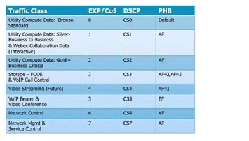
Note that in some data center QoS models, CoS 3 is reserved for lossless data (FCoE). However, in alternative WAN/campus QoS services models, CoS 3 is used for voice over IP (VoIP) signaling. This table assumes that FCOE traffic is localized to UCS and Ethernet-attached storage systems, enabling the use of CoS 3 for VoIP signaling traffic in the data center QoS domain. Classification values may need to be tweaked per traffic characteristics; for example, CoS 4 could potentially be used for VoIP call control if video streams are not deployed.
It is a general best practice to mark traffic at the source-end system, or as close to the traffic source as possible, to simplify network design. However, if the end system cannot mark or cannot be trusted, marking can be performed on network ingress. In the VMDC QoS framework, the cloud data center represents a single QoS domain, with the Nexus 1000V forming the "southern" access edge, and the ASR 9000 or ASR 1000 forming the "northern" DC PE/WAN edge. These QoS domain edge devices mark traffic, and these markings are trusted at nodes within the data center infrastructure. In other words, they use simple classification based on the markings received from the edge devices. Note that where VM-FEX adapters are used, marking is implemented on UCS Fabric Interconnects; in contrast to the Nexus 1000V implementation, there is no ability to conditionally mark-down CoS in the event of congestion.
In VMDC, the assumption is that DSCP values are not altered. Intermediate nodes would ideally support QoS transparency, so that CoS values would not need to be re-marked. That said, if QoS transparency is not supported on a particular node within the QoS domain, it will be necessary to workaround this gap by re-marking.
In VMDC VSA 1.0, the Netscaler vSLB does not support QoS transparency. The insertion of CSR as the tenant virtual private cloud represents a trust boundary. In these cases, it is necessary to classify and remark at the CSR.
These notes apply specifically to the VSA 1.0.2 QoS implementation:
- The insertion of CSR as the tenant virtual private cloud represents a trust boundary. In these cases, it is necessary to classify and remark at the CSR.
- Nexus 9000 Series Switches support ingress traffic classification. On an ingress interface traffic can be classified based on the address fields, 802.1q CoS, and IP Precedence or DSCP in the packet header. The classified traffic can be assigned to one of the four qos-groups. The qos-groups serve as an internal identification of the traffic classes that is used for the subsequent QoS processes as packets go through the system.
Traffic reaching the Nexus 9300 access-edge and 9508 aggregation/core layer is classified on ingress, based on the COS value (previously set at the edges of the Data Center QoS domain or at the CSR trust boundary) and mapped to a corresponding QOS queue group at ingress.
Queuing, Scheduling, and Dropping
In a router or switch, the packet scheduler applies policy to decide which packet to dequeue and send next, and when to do it. Schedulers service queues in different orders. The most frequently used are:
We use a variant of weighted bandwidth queuing called class-based weighted fair queuing/low latency queuing (CBWFQ/LLQ) on the Nexus 1000V at the southern edge of the data center QoS domain. At the ASR 9000 or ASR 1000 northern data center WAN edge, we use priority queuing (PQ)/CBWFQ to bound delay and jitter for priority traffic while supporting weighted bandwidth allocation for the remaining data traffic classes.
Queuing mechanisms manage the front of a queue, while congestion avoidance mechanisms manage the back of a queue. Because queue depths are limited, dropping algorithms, which drop packets as queue depths build, are used to avoid congestion. Two dropping algorithms are commonly used: weighted tail drop (often for VoIP or video traffic) or weighted random early detection (WRED), typically for data traffic classes. As in previous releases, WRED is used to drop out-of-contract data traffic (CoS 1) before in-contract data traffic (Gold and CoS 2), and for Bronze/Standard traffic (CoS 0) in the event of congestion.
On the Nexus 9500 aggregation/core switches used in this release, the buffer manager performs ingress accounting and admission functions on traffic in the ingress processing pipeline. Both line cards and fabric modules of the Cisco Nexus 9500 Series are equipped with multiple network forwarding engines (NFE) that perform packet lookup, processing and forwarding functions. Each NFE has a 12 MB buffer that is dynamically shared by ingress and egress traffic. The ingress admission control mechanism decides if a packet should be admitted into the memory. This decision is based on the amount of buffer memory available and the amount of buffer already utilized by the ingress port and traffic class.
The Nexus 9000 systems effectively implement an egress queuing architecture. In contrast to many other Cisco switch architectures, there are no Virtual Output queues on ingress to line cards. In the event of egress port congestion, packets are directly queued in the buffer of the egress line card. A Nexus 9500 switch can support up to six traffic classes on egress (four user defined classes identified by qos-group IDs, a CPU control traffic class and a SPAN traffic class). Each user defined class can have a unicast queue and a multicast queue per egress port. The 12 MB buffer on an NFE is shared among the local ports. The switch software has a mechanism to meter and limit buffer utilization per egress port. This ensures that no single port can consume more than its fair share of the buffer memory.
Defining an end-to-end QoS architecture can be challenging because not all nodes in a QoS domain have consistent implementations. In the cloud data center QoS domain, we run the gamut from systems that support 16 queues per VEM (Nexus 1000V) to four internal fabric queues (i.e., Nexus 7000) or user-defined queues (i.e., Nexus 9000). This means that traffic classes must be merged on systems that support less than eight queues. Figure 2-26 shows the class-to-queue mapping that applies to the cloud data center QoS domain in the VMDC reference architecture, in the context of alignment with either the HCS reference model or the more standard NGN reference.
Figure 2-26 VMDC Class-to-Queue Mapping
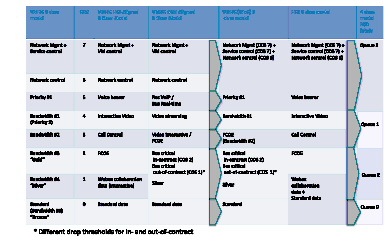
Note The Nexus 2000 Fabric Extender provides only two user queues for QoS support: one for all no-drop classes and the other for all drop classes. The classes configured on its parent switch are mapped to one of these queues; traffic for no-drop classes is mapped to one queue and traffic for all drop classes is mapped to the other. Egress policies are also restricted to these classes.
Shaping and Policing
Policing and shaping are used to enforce a maximum bandwidth rate (MBR) on a traffic stream; while policing effectively does this by dropping out-of-contract traffic, shaping does this by delaying out-of-contract traffic. In general, VMDC uses policing in and at the edges of the cloud data center QoS domain to rate-limit data and priority traffic classes. At the data center WAN edge/PE, hierarchical QoS (HQoS) may be implemented on egress to the cloud data center; this uses a combination of shaping and policing in which L2 traffic is shaped at the aggregate (port) level per class, while policing is used to enforce per-tenant aggregates. Sample bandwidth port reservation percentages are shown in Figure 2-27.
Figure 2-27 Sample Bandwidth Port Reservations
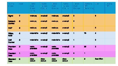
Figure 2-28 and Figure 2-29 summarize the QoS mechanisms employed intra-DC in this release:
Figure 2-28 IntraDC QoS, North to South
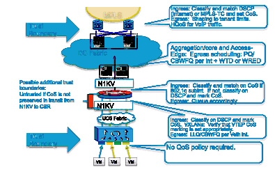
Figure 2-29 Sample Bandwidth Port Reservations
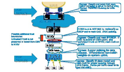
Application Visibility and Control
Cisco's Application Visibility and Control solution is a suite of services for application classification, traffic control and monitoring that support capacity planning and resource management, improve business-critical application performance, and in the public environment, allow for highly tuned service assurance. Technologies such as Quality of Service, previously discussed, Network Based Application Recognition, Netflow, Network Analysis and Application Optimization form the basis of this solution set.
NBAR
Cisco Network Based Application Recognition (NBAR) provides the option of using stateful deep packet inspection for granular, application-level traffic inspection and traffic classification for performance monitoring and tuning or for other use cases, such as application monitoring for security purposes. NBAR currently provides the ability to identify over 1000 application signatures. NBAR is also capable of defining customized application profiles based on ports, URL or even payload values. NBAR is implemented in hardware on physical routers such as the ASR1000 or ISRG2, however on the CSR, NBAR is software-based. This means that caution should be employed in deploying NBAR to understand the impact on forwarding performance and insure the desired packet throughput.
NetFlow
Cisco developed NetFlow to provide better insight into IP traffic. A key component of Cisco's Application, Visibility and Control suite of features and functionality, NetFlow defines flows as records and exports the records to collection devices. NetFlow provides information about the applications in and utilization of the data center network. The NetFlow collector aggregates and assists network administrators and application owners to interpret the performance of the data center environment.
The use of NetFlow is well documented in traditional network environments, but the Nexus 1000V provides this capability in the virtual network environment. Nexus 1000V supports NetFlowv9 and by default uses the management 0 interface as an export source.

CPU). It is important to understand these resource dynamics before enabling advanced features.
Figure 2-30 shows the Cisco NAM application traffic statistics on the Nexus 1000V virtual Ethernet interfaces. The Nexus 1000V can also monitor flows from the physical interfaces associated with the platform and VMkernel interfaces including vMotion traffic, as seen in Figure 2-31.
Figure 2-30 Cisco NAM Traffic Summary
Figure 2-31 Cisco Netflow Collector Nexus 1000v vMotion Results Example
ERSPAN supports remote monitoring of network resources. ERSPAN uses generic routing encapsulation (GRE) tunnels to route traffic. The Nexus 1000V supports ERSPAN, enabling network administrators to observe traffic associated with:
- The individual vNIC of a VM connected to a VEM
- The physical ports associated with the ESXi host
- Any port channels defined on the VEM
This flexibility enables ERSPAN sessions to monitor data associated with VM’s, and to monitor all traffic associated with the ESXi host including VMkernel, vMotion, and service console data. Converging these traffic types onto two or a maximum of four CNAs per-ESXi host simplifies physical data center design and the configuration of capture points.
In the validation of this solution, the final destination for ERSPAN traffic was the Virtual Network Analysis Module (vNAM), resident in the compute layer of the infrastructure in vApp form factor.
For more information about configuring ERSPAN on the Nexus 1000V, follow this link:
http://www.cisco.com/en/US/docs/switches/datacenter/nexus1000/sw/4 0 4 s v 1 2/system_manage ment/configuration/guide/n1000v_system_9span.html
Figure 2-32 and Figure 2-33 show examples of a packet decode and application performance metrics available from the ERSPAN data.
Figure 2-32 View of NAM Captured Data from VM NIC
Figure 2-33 Application Response Time Data Collected on Nexus 1000V VEM Uplink
Performance Agent
Cisco Performance Agent is a licensed feature of Cisco IOS Software, providing embedded instrumentation for application analytics. Based upon deep packet inspection capabilities of NBAR (Network Based Application Recognition), Performance Agent offers comprehensive application performance and network usage data to help network administrators accurately assess user experience and optimize the use of network resources. Cisco Performance Agent works with other Cisco IOS Software Application Visibility and Control features, such as Netflow, NBAR and QoS, as well as the Cisco Network Analysis Module (NAM or vNAM) and the WAAS or vWAAS. Once enabled, Performance Agent may be configured to export application performance analytics, traffic statistics, and WAN-optimization statistics, delivering combined metrics gathered from Netflow, NBAR and NAM monitoring if desired. The information may be delivered to third party management tools in a Netflow v9 format or presented to the Cisco Prime NAM or WAAS vCM consoles in GUI reporting fashion. Performance Agent is supported on the ASR1000, ISRG2 and CSR routers utilized in this systems release. More information on Performance Agent is available online .
Network Analysis
The use of network analysis devices is another application visibility service readily available in the VMDC design. The Cisco Nexus 1000V NAM VSB is integrated with the Nexus 1100 Virtual Services Appliance to provide network and performance visibility into the Nexus 1000V switching deployment.
In VSA release 1.0, we also introduced the vNAM, a new vAPP-based form-factor that leverages the Nexus 1000v for traffic redirection and visibility. Cisco vNAM is introduced with Cisco Prime NAM software release 6.0. This software release introduces several new features enhancing overall application and performance visibility, including enhanced classification capabilities leveraging the Nexus 1000v DVS, and support for VXLAN, LISP and OTV encapsulations. For VMDC VSA 1.0 and 1.0.1, which uses VXLANs to scale segmentation within the compute layer of the infrastructure, the latter is key to making this type of "overlay" technology feasible from an operational perspective.
The NAM VSB and new vNAM use embedded instrumentation, such as NetFlow and Encapsulated Remote SPAN (ERSPAN) or SPAN on the Nexus 1000V switch as the data source for traffic analysis, application response time, interface statistics, and reporting. Alternatively, in VMDC VSA 1.0/1.0.1, the CSR vCE, as the Virtual Private Cloud boundary point provides another source for SPAN or ERSPAN of aggregated traffic statistics for network analysis.
Refer to NAM for Nexus 1100 for more information.
Refer to vNAM for more information.
Application Optimization
Wide Area Application Services or WAAS (WAAS) is another key component of Cisco's Application Visibility and Control suite of products, providing application-centric acceleration services over the wide area. For information on how WAAS was utilized in VMDC VSA 1.0, refer to Cisco vWAAS.
Cloud Service Assurance for VMDC
Cloud Service Assurance for VMDC (CLSA-VMDC), based on the Zenoss Cloud Service Assurance solution, is a service-impact model-based system for tenant-based service assurance. CLSA-VMDC supports consolidated VMDC infrastructure monitoring and simple, easily-deployed plug-ins for customization. CLSA-VMDC offers real-time aggregated dashboards and reporting capabilities. CLSA-VMDC can be deployed in centralized and distributed architectures, and supports incremental deployment growth. While CLSA-VMDC offers rich functionality for IaaS domains, the solution is lightweight and has open interfaces to enable simple integration into existing operations support system (OSS) and ticketing systems with minimal cost. This solution is positioned not as a replacement, but as a complement to existing Manager-of-Manager (MOM) systems (for example, IBM Netcool), ticketing systems (for example, BMC Remedy), and so on. Additional documentation can be found on Design Zone at Data Center and Cloud Service Assurance.
Storage QoS
Tenant workloads in the VMDC data center should be prevented from affecting each other. While this is handled by QoS mechanisms at the network layer, those QoS mechanisms do not protect performance at the storage layer. Because all storage I/O traffic is classed the same in the VMDC data center, all tenants receive an equal share of the storage performance capacity unless controlled by some other mechanism. Without implementing performance limits on storage I/O, the performance of one tenant workload may suffer due to the overwhelming use of storage I/O by a neighboring tenant workload sharing the same physical hardware.
Additionally early adopter tenants' workloads may experience higher than normal performance early in a PoD lifecycle due to the low number of tenants using the resources. Without setting storage performance caps those tenants may perceive a decrease in storage performance once the tenant capacity for their PoD has been reached. Even though the performance level they are receiving may be within the bounds of the tenant's service level agreement, the tenant may perceive that performance has dropped below the expected level.
NetApp FAS controllers running clustered Data ONTAP prevent workloads from impacting each other through the use of Storage Quality of Service (Figure 2-34).
Figure 2-34 Application of Storage QoS
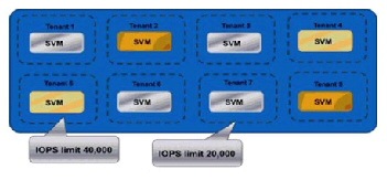
NetApp Storage QOS allows I/O ceilings do be defined in terms of IOPS. Those performance ceilings can be applied to individual workloads or to groups of workloads. In a multi-tenant environment, a tenant could have IOPS limits set across all workloads hosted within a particular ICS or could have limits set on each deployed workload.
For additional information on NetApp Storage QoS, see http://www.netapp.com/us/media/wp-7191.pdf.
Storage Oversubscription
In a shared storage environment, thin provisioning is a method for optimizing utilization of available storage through oversubscription. It relies on on-demand allocation of blocks of data versus the traditional method of allocating all the blocks up front. This methodology eliminates almost all white space, which helps avoid poor utilization rates that may occur in the traditional storage allocation method where large pools of storage capacity are allocated to individual servers but remain unused. In this model, thinly provisioned pools of storage may be allocated to groups of vApps with homogenous workload profiles. Utilization will be monitored and managed on a pool-by-pool basis.
In the Integrated Compute Stack layer of the VMDC architecture, in the context of a FlexPod environment, thin provisioning, data deduplication, and FlexClone thincloning technology are the critical components of the NetApp solution, offering multiple levels of storage efficiency across the virtual desktop OS data, installed applications, and user data. This helps customers save 50% to 90% of the cost associated with shared storage (based on existing customer de-ployments and NetApp solutions lab validation). Thin provisioning is a method of logically pre-senting more storage to hosts than is physically available. With thin provisioning, the storage administrator can access a pool of physical disks (known as an aggregate) to create logical vol-umes for different applications to use, without pre-allocating space to those volumes. The space is allocated only when the host needs it. Thus unused aggregate space is available for the existing thin-provisioned volumes to expand or for use in the creation of new volumes. NetApp deduplication saves space on primary storage by removing redundant copies of blocks in a volume that may be hosting hundreds of virtual desktops. This process is transparent to the application and user and can be enabled and disabled on the fly. Using NetApp deduplication in conjunction with file FlexClone technology can reduce the overall storage footprint of virtual machines.
Storage Service Tiering
Service differentiation in the VMDC reference architecture is a composite of differentiated network services (QoS policy, security, server load balancing, SSL offload, application control/optimization); differentiated compute attributes; and differentiated storage and business continuance characteristics.
Figure 2-35 shows this concept, demonstrating a variety of ways in which these resources and services can be applied in various combinations to meet business or application requirements in a tiered fashion.
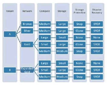
With respect to storage resources, the following methods may be utilized to differentiate storage services to meet tenant application requirements and insure service continuity:
- Storage Tiering—A mixture of various types of storage drives (SATA, SAS, flash) with differing capacity, performance and reliability characteristics are applied to meet application IOPs requirements.
- Storage Protection—Storage protection options in the form of datastore snapshots to provide point in time file copies, or cloning for data volume or dataset replication.
- Disaster Recovery—Application of synchronous or asynchronous data replication technologies from source to target storage system for backup and recovery from secondary facilities for mission-critical applications.
In the context of FlexPod and NetApp storage arrays, the following links provide more information on tiering, replication, backup, and DR technologies:
- Virtual Storage Tiering: http://www.netapp.com/in/technology/virtual-storage-tier/index.aspx
- SnapMirror Datasheet: http://www.netapp.com/in/products/protection-software/snapmirror.aspx
- SnapMirror Best Practices: http://www.netapp.com/us/media/tr-4015.pdf
- SnapVault Datasheet: http://www.netapp.com/in/products/protection-software/snapvault.aspx
- SnapVault Best Practices: http://www.netapp.com/us/media/tr-4183.pdf
 Feedback