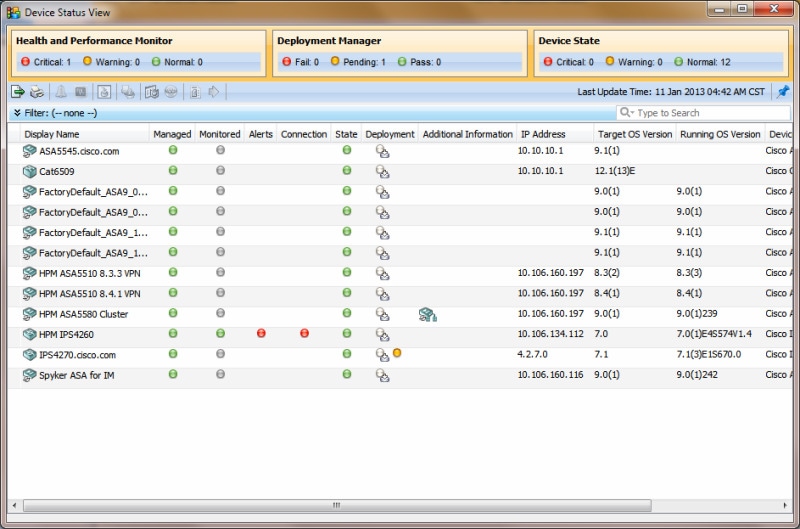
Managing the Device Inventory

The following topics describe how to manage the device inventory:

Understanding the Device Inventory

Security Manager maintains an inventory of the devices that it manages. The inventory includes the information required to locate and log into the device, so that your policies can be deployed to the devices. The following topics describe some general concepts related to the device inventory:

Understanding the Device View

The Device View button opens the Devices page, from which you can add and delete devices from the Security Manager inventory and manage device policies, properties, and interfaces centrally.

This is a device-centric view in which you can see all devices that you are managing and you can select specific devices to view their properties and define their settings and policies. You can define security policies locally on specific devices. You can then share those policies to make them globally available to be assigned to other devices.

The Devices page contains two panes. The left pane contains two elements: the Device selector, located in the top left pane, and the Policy selector, located in the bottom left pane. The right pane is the main content area. The following illustration shows the Devices page.
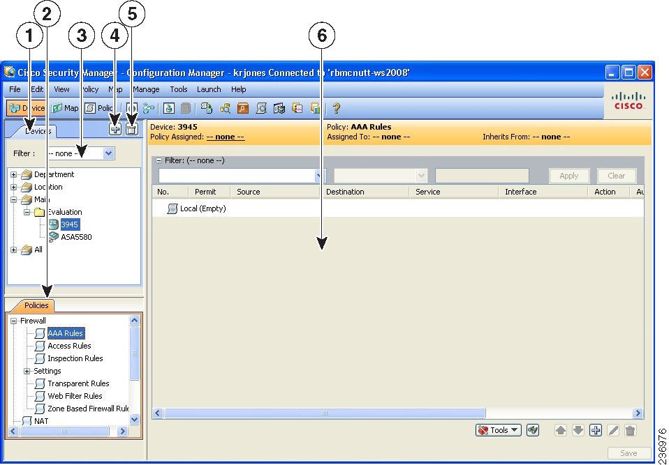
Figure 1. Devices Page

Device selector (1, 3, 4, 5)—Contains the following:

  • Add and Delete buttons (4, 5)—Enables you to add and delete devices from the Security Manager inventory.

  • Filter field (3)—Enables you to display a subset of devices based on the filtering criteria you define. For details, see Filtering Items in Selectors.

  • Device tree—Lists the device groups and devices that exist in the system. Each device type is represented by an icon. For information about the icons, see Figure 3-2.

If you hover the mouse pointer over a device, detailed information about the device appears in a popup window. The information is a summary of the device properties (see Device Properties: General Page).


Note

Beginning from version 4.8, Security Manager displays the updated version information of a device that has been upgraded using Auto Update Server (AUS). To enable this feature you must configure Security Manager details in the AUS user interface. If you hover the mouse over a device, the following message appears if AUS has successfully updated the device version:

"State Description: Version update is successfully completed by Auto Update Server. Check if any other configuration changes are required in Security Manager."

Figure 2. Device Icons

1

Adaptive Security Appliances (ASA)

5

Catalyst Switch

2

PIX Firewall

6

Catalyst 7600 Series Router

3

Catalyst security Services Modules: Firewall Services Module (FWSM) and ASA-SM

7

VPN 3000 Concentrator

4

Cisco IOS Router

8

Intrusion Prevention System (IPS)

  • Shortcut menu options—When you right-click a device or device group, you get a menu of commands related to that device or group. These commands are shortcuts to commands available in the regular menus.

Policy selector (2)—Contains the following:

  • Policy groups—Lists the policy groups that are supported on the selected device type. The policy groups that are displayed are dependent on four factors:

    • The type of device selected in the Device selector.

    • The operating system running on the device.

    • The target operating system version selected for determining which commands will be available for generated configurations.

    • Whether the device contains supported service modules.

For more information about policies, see Understanding Policies

  • Shortcut menu options—When you right-click a policy, you get a menu of commands related to that policy. These commands are shortcuts to commands available in the regular menus.

Contents pane (6)—The main content area.

The information displayed in this area depends on the device you select from the Device selector and the option you select from the Policy selector.

Understanding Device Names and What Is Considered a Device

Besides managing traditional devices, you can use Security Manager to manage virtual devices that you can define on some types of security devices. These virtual devices are treated as separate devices in the device inventory, and they appear as separate entries in the device selectors. Because these virtual devices actually reside on a host physical device, many actions, such as deployment, will have to include the host device as well as the virtual device.

All physical devices appear in the device selectors. In addition, these are the types of virtual devices that appear in the device selectors:

  • Security Contexts—You can define security contexts on PIX Firewall, FWSM, and ASA devices. Security contexts act as virtual firewalls. By default, security contexts appear in the device selectors using this naming convention: host-display-name_context-name , where host-display-name is the display name of the device on which the context is defined, and context-name is the name of the security context. For example, the admin security context on the device named firewall12 would be called firewall12_admin.


Tip

You can control whether the display name is added to the context name using the Prepend Device Name when Generating Security Context Names property on the Discovery settings page (see Discovery Page). However, if you do not add the display name, it is very difficult to determine the hosting device for a context, and the context names are not sorted with the host device (they do not appear in a folder attached to the host device). If you do not add the display name, Security Manager adds a numeric suffix to the context name if more than one context of the same name is added to the inventory (for example, admin_01, admin_02), and these numbers are not related to the host device.
  • Virtual Sensors—You can define virtual sensors on IPS devices. Virtual sensors appear in device selectors using the host-display-name_virtual-sensor-name naming convention, and there is not a discovery setting to control this convention.


Tip

You can always change the display name for a virtual sensor, security context, or other type of device in the device’s properties.

Besides the naming conventions for virtual devices, you also need to understand the relationship between various types of device names:

  • Display name—The display name is simply the name that appears within Security Manager in device selectors. This name does not have to be related to any name actually defined on the device. When you add devices to the inventory, a display name is suggested based on the DNS name or IP address you enter, but you can use whatever naming convention you want to use.

  • DNS name—The DNS name you define for a device must be resolvable by the DNS server configured for the Security Manager server.

  • IP address—The IP address you define for a device should be the management IP address for the device.

  • Hostname—When you discover a device, the hostname property that is shown in the device properties is taken from the device’s configuration. If you add devices using configuration files, and a file does not contain a hostname command, the initial hostname is the name of the configuration file.

However, the hostname device property is not updated if you change the hostname on the device. There is a Hostname policy in the device platform policy area, and it is this Hostname policy that determines the hostname that is defined on the device.

Understanding Device Credentials

Security Manager requires credentials for logging in to devices. You can provide device credentials in two ways:

You can provide the following device credentials:

  • Primary Credentials—The username and password for logging into the device using SSH or Telnet. This information is required for device communication.

  • HTTP Credentials—Some devices allow HTTP or HTTPS connections, and some devices (such as IPS devices) require it. By default, Security Manager uses the primary credentials for HTTP/HTTPS access, but you can configure unique HTTP/HTTPS credentials.

  • RX-Boot Mode—(Optional) Some Cisco routers are designed to run from flash memory where they boot only from the first file in flash. This means that you must run an image other than the one in flash to upgrade the flash image. That image is a reduced command-set image referred to as RX-Boot (a ROM-based image).

  • SNMP Credentials—(Optional) The Simple Network Management Protocol (SNMP) facilitates the exchange of management information between network devices. SNMP enables network administrators to manage network performance, find and solve network problems, and plan for network growth.


Note

PIX/ASA/FWSM devices require that user names be at least four characters. Passwords can be three to 32 characters; we recommend that passwords be at least eight characters. For ASA devices running the software version 9.6(1) or later, you can enter a password up to 127 characters.

Rather than using device-based credentials, you can configure Security Manager to use the credentials you use when you log into Security Manager. You can then use the AAA server’s accounting facilities to track configuration changes by user. Using user login credentials is suitable only if your environment is configured according to these standards:

  • You use TACACS+ or RADIUS for change auditing. User-login credentials will be reflected in these accounting records. If you use device credentials, all changes made through Security Manager will come from the same account, regardless of which user made the change.

  • User accounts are configured in the AAA server, and they have appropriate device-level access to perform configuration changes.

  • You configure Security Manager and the managed devices to use the AAA server for authorization. For information on configuring Security Manager to use AAA, see the Installation Guide for Cisco Security Manager .

  • You do not use one-time passwords.

If your network setup supports using user-login credentials, you can configure Security Manager to use them by selecting Tools > Security Manager Administration. Select Device Communication from the table of contents, and select Security Manager User Login Credentials in the Connect to Device Using field. The default is to use device credentials for all device access.

Related Topics

Understanding Device Properties

You define device properties when you add devices to Security Manager. Device properties are general information about the device, credentials, the group the device is assigned to, and policy overrides. You must provide some device property information, such as device identity and primary credentials, when you add the device, but you can add or edit the properties from the Device Properties dialog box.

To view the device properties, do one of the following in the Device selector:

  • Double-click a device.

  • Right-click a device and select Device Properties.

  • Select a device and select Tools > Device Properties.

The Device Properties dialog box has two panes. The left pane contains a table of contents with these items:

  • General—Contains general information about the device, such as device identity, the operating system running on the device, and device communication settings.

  • Credentials—Contains device primary credentials (username, password, and enable password), SNMP credentials, Rx-Boot Mode credentials, and HTTP credentials.

  • Device Groups—Contains the groups to which the device is assigned.

  • Cluster Information—Contains detailed informatio for the cluster group, if any.

  • Policy Object Overrides—Contains global settings of certain types of reusable policy objects that you can override for this device.

When you select an item in the table of contents, the corresponding information is displayed in the right pane.

Notes

  • Security Manager does not assume that the DNS hostname that appears on the Device Properties page is the same as the hostname that you configured on the device.

  • When you add a device to Security Manager, you must enter either the management IP address or the DNS hostname. Because it is not possible to determine the management interface and, therefore, the management IP address when you discover from a configuration file, the hostname in the configuration file is used as the DNS hostname. If the hostname is missing in the CLI of the configuration file, the configuration filename is used as the DNS hostname.

  • When you discover a device from the network, the DNS hostname in the Device Properties page is not updated with the hostname configured on the device. Therefore, if you want to specify the DNS hostname for the device, you must specify it manually when you add the device to Security Manager or on the Device Properties page.

For more information about device properties, see Viewing or Changing Device Properties.
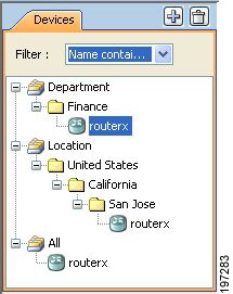
Adding Devices to the Device Inventory

When you add a device to Security Manager, you specify the identifying information for the device, such as its DNS name and IP address. This information is added during device discovery. You can also bring in existing network configurations associated with a device by initiating policy discovery. For complete information on policy discovery, see Discovering Policies. Once you add the device, it appears in the Security Manager device inventory.

The New Device wizard guides you through the process of adding devices to the inventory. You can add devices from many different sources, and the path through the wizard differs significantly based on the method you are using.


Note

Beginning with Cisco Security Manager 4.21, although ASA software enhancements and bug fixes are still supported, any hardware support for routers is not rendered, as Cisco IOS Software has reached its end of life.

To start the New Device wizard, from Device view, select File > New Device, or click the Add button in the device selector.


Note

There is also another way to add devices. If you exported a .dev file from another Security Manager server, which contains not only a device inventory but also the policies and policy objects assigned to them, you can import the file using the File > Import command. For more information, see Importing Policies or Devices.

Tips on Adding Devices and Service Modules

  • For PIX Firewalls and FWSM and ASA devices that are configured for failover, add only the active unit to Security Manager. Ensure that the device is configured with a management IP address and use that address for discovery. When discovering Catalyst switches that contain more than one service module (FWSM or ASA-SM) configured for failover, when prompted, select Do Not Discover Module for the failover modules. Security Manager always manages the active admin context, regardless of whether you added the primary or secondary failover service module.

  • Security Manager can manage ASA clusters after they have been configured as a cluster using the CLI bootstrapping as defined in the ASA Configuration Guide (see http://www.cisco.com/en/US/products/ps6120/products_installation_and_configuration_guides_list.html ). All the members of a cluster are assigned individual IP addresses during the bootstrap process. When adding a cluster to Security Manager, you do so by discovering the cluster using the main cluster IP address. The main cluster IP address is a fixed address for the cluster that always belongs to the current control unit. This is not the control unit’s individual IP Address. For more information about clusters, see Working with Device Clusters.

  • Service modules are treated as separate devices. For most modules, you must add the service module separately from its host device. However, Security Manager can automatically discover FWSM or IDSM modules in a Catalyst 6500 device, so you need only add the parent device. (You cannot discover an ASA-SM during discovery of the parent device. You must add the ASA-SM separately.) The only exception is if you configure an FWSM or IDSM module to use a non-default port for HTTPS (SSL), in which case you must add the module separately.

  • When adding an ASA-SM or FWSM that has multiple security contexts (they are running in multiple-context mode), do not add the security contexts individually using their management IP addresses. Instead, add the device using the admin context management address (this also adds the individual contexts). Then, configure Security Manager to deploy configurations to multiple-context devices serially as described in Changing How Security Manager Deploys Configurations to Multiple-Context FWSM.

  • You cannot add devices beyond the device limits defined by your Security Manager license. For example, if you have a license for 50 devices, and there are 45 devices in the inventory, if you try to add a multiple-context ASA with 6 security contents, the device addition and discovery fails.

The following topics describe the various methods of adding devices:

  • Add Device from Network—To add devices that are currently active on the network, see Adding Devices from the Network. Security Manager connects directly and securely to the device and discovers its identifying information and properties.

    • Pros—You need to specify minimal information about a device, and Security Manager obtains the detailed information directly from the device, ensuring accuracy.

    • Cons—You can add only one device at a time. You cannot add devices that have dynamic IP addresses, unless you determine the device’s current IP address, add it using that address, and then update the device properties in Security Manager to identify the Configuration Engine that is managing the device.

  • Add from Configuration File—To add devices by using a copy of the device configuration files, see Adding Devices from Configuration Files.

    • Pros—You can add more than one device at a time.

    • Cons—You cannot use this method to add Catalyst 6500/7600 or IPS devices. When adding groups of configuration files, all files must be for the same device type.

Also, you cannot successfully discover policies that require a connection with the device. For example, if a policy points to a file that resides on the device, adding the device using the configuration file will result in a Security Manager configuration that includes the no form of the command, because Security Manager cannot retrieve the referenced file from the device. For example, the svc image command for web VPNs might be negated.

  • Add New Device—To add a device that does not yet exist in the network, so that you can pre-provision it in Security Manager, see Adding Devices by Manual Definition. You can create the device in the system, assign policies to the device, and generate configuration files before installing the device hardware.

    • Pros—You can pre-provision devices that do not yet exist in the network.

    • Cons—You must specify more information than that required by any other method. If you create a Catalyst 6500 device, or a router that contains an IPS module, you should discover its modules by selecting Policy > Discover Policies on Device.

  • Add Device from File—To add devices from an inventory file in comma-separated values (CSV) format, see Adding Devices from an Inventory File.

    • Pros—You can add multiple devices of different types at one time. You can reuse the inventory list from your other network management applications, including CiscoWorks Common Services, Cisco Security Monitoring, Analysis and Response System (CS-MARS), and other Security Manager servers. If you use a file exported from another Security Manager server, you can optionally add the devices without discovering policies, which is convenient for adding offline or standby devices.

    • Cons—You cannot use this method to update the properties of devices already defined in the inventory. Also, policy discovery can fail if you attempt to import more than 100 devices at one time, and might fail for even fewer devices. In the case of IPS devices, do not add more than four IPS devices at a time to avoid policy discovery failures.

Working with Device Clusters

Clustering lets you group multiple ASAs together as a single logical device. A cluster provides all the convenience of a single device (management, integration into a network) while achieving the increased throughput and redundancy of multiple devices. Clustering is supported on ASA 5580 and 5585 devices running 9.0(1) or later and on ASA 5512-X, 5515-X, 5525-X, 5545-X and 5555-X devices running 9.1(4) or later.

Security Manager can manage ASA clusters after they have been configured as a cluster using the CLI bootstrapping as defined in the ASA Configuration Guide (see http://www.cisco.com/en/US/products/ps6120/products_installation_and_configuration_guides_list.html ).

All the members of a cluster are assigned individual IP addresses during the bootstrap process. When adding a cluster to Security Manager, you do so by discovering the cluster using the main cluster IP address. The main cluster IP address is a fixed address for the cluster that always belongs to the current control unit. This is not the control unit’s individual IP Address.


Note

You cannot convert a standalone device to a cluster in Security Manager by rediscovering the device after performing the necessary CLI bootstrapping. You must first delete the device from Security Manager, and then after performing the necessary CLI bootstrapping, you can add the cluster to Security Manager as a new device.

The cluster is represented as a single device in Security Manager. After the cluster has been added to Security Manager, you can finish configuring the cluster settings such as cluster interfaces and security policies.


Note

Clustering has specific configuration requirements and restrictions. Please refer to the ASA documentation at http://www.cisco.com/en/US/products/ps6120/products_installation_and_configuration_guides_list.html for detailed information about requirements, configuration recommendations, and performance information.

Unsupported Features on ASA Clusters

These features cannot be configured with clustering enabled, and the commands will be rejected.

  • Unified Communications

  • Remote access VPN (SSL VPN and IPsec VPN)

  • The following application inspections:

    • CTIQBE

    • GTP

    • H323, H225, and RAS

    • IPsec passthrough

    • MGCP

    • MMP

    • RTSP

    • SIP

    • SCCP (Skinny)

    • WAAS

    • WCCP

  • Botnet Traffic Filter

  • Auto Update Server

  • DHCP client, server, relay, and proxy

  • VPN load balancing

  • Failover

  • ASA CX module

Centralized Features

The following features are only supported on the control unit, and are not scaled for the cluster. For example, you have a cluster of eight units (5585-X with SSP-60). The Other VPN license allows a maximum of 10,000 IPsec tunnels for one ASA 5585-X with SSP-60. For the entire cluster of eight units, you can only use 10,000 tunnels; the feature does not scale.


Note

Traffic for centralized features is forwarded from member units to the control unit over the cluster control link; see "Sizing the Cluster Control Link" in the ASA documentation to ensure adequate bandwidth for the cluster control link. If you use the rebalancing feature, traffic for centralized features may be rebalanced to non-control units before the traffic is classified as a centralized feature; if this occurs, the traffic is then sent back to the control unit. For centralized features, if the control unit fails, all connections are dropped, and you have to re-establish the connections on the new control unit.
  • Site-to-site VPN

  • The following application inspections:

    • DCERPC

    • NetBios

    • PPTP

    • RADIUS

    • RSH

    • SUNRPC

    • TFTP

    • XDMCP

  • Dynamic routing (spanned EtherChannel mode only)

  • Multicast routing (individual interface mode only)

  • Static route monitoring

  • IGMP multicast control plane protocol processing (data plane forwarding is distributed across the cluster)

  • PIM multicast control plane protocol processing (data plane forwarding is distributed across the cluster)

  • Authentication and Authorization for network access. Accounting is decentralized.

  • Filtering Services

Features Applied to Individual Units

These features are applied to each ASA unit, instead of the cluster as a whole.

  • QoS—The QoS policy is synced across the cluster as part of configuration replication. However, the policy is enforced on each unit independently. For example, if you configure policing on output, then the conform rate and conform burst values are enforced on traffic exiting a particular ASA. In a cluster with 8 units and with traffic evenly distributed, the conform rate actually becomes 8 times the rate for the cluster.

  • Threat detection—Threat detection works on each unit independently; for example, the top statistics is unit-specific. Port scanning detection, for example, does not work because scanning traffic will be load-balanced between all units, and one unit will not see all traffic.

  • Resource management—Resource management in multiple context mode is enforced separately on each unit based on local usage.

  • IPS module—There is no configuration sync or state sharing between IPS modules. Some IPS signatures require IPS to keep the state across multiple connections. For example, the port scanning signature is used when the IPS module detects that someone is opening many connections to one server but with different ports. In clustering, those connections will be balanced between multiple ASA devices, each of which has its own IPS module. Because these IPS modules do not share state information, the cluster may not be able to detect port scanning as a result.

Related Topics

Adding Devices from the Network

One of the easiest and most reliable ways to add devices to the inventory is to identify devices that are active in the network. By providing the IP address (or DNS hostname) of a device, and the credentials required to log into it, Security Manager can obtain much of the information it needs directly from the device, ensuring the accuracy of the information.

Before You Begin

Before beginning this procedure, ensure the following preparations have been made:

Related Topics

Procedure


Step 1

In Device view, select File > New Device or click the New Device button in the Device selector. The New Device wizard opens to the Choose Method page.

Step 2

On the Choose Method page, select Add Device from Network and click Next to open the Device Information page.

Step 3

On the Device information page, at minimum fill in the following fields. For a detailed explanation of all fields, see Device Information Page – Add Device from Network.

  • Enter either a hostname and DNS name, or an IP address (or both).

  • Enter a display name, which is the name that will appear in the Security Manager Device selector.

  • Select the correct operating system and version. If you are configuring a Catalyst switch or a 7600 router, ensure that you select IOS - Catalyst Switch/7600 rather than one of the other IOS entries.

  • Select the transport protocol that should be used to log into the device, if the device is configured to use a protocol that differs from the default defined in Security Manager. The default is set on the Device Communication administration page (see Device Communication Page).

Click Next.

Step 4

On the Device Credentials page, enter the usernames and passwords required to log into the device. Enter at least the primary device credentials, which are the traditional User EXEC mode and Privileged EXEC mode passwords.

For information on the different types of credentials, see Device Credentials Page.

Tip 
When you click Next or Finished from the Device Credentials page, Security Manager tests whether it can connect to the device. You cannot add the device unless the test succeeds. For more information, see Testing Device Connectivity.
Step 5

(Optional) Click Next to open the Device Grouping page, and select the device group to which the imported devices should be added (see Device Groups Page).

Step 6

Click Finish. Security Manager opens the Discovery Status dialog box where you can view the status of the device discovery and policy analysis (see Discovery Status Dialog Box).

Tip 
If you are discovering policies while adding a device, carefully read any messages that are presented to you. These messages can contain important recommendations on the next steps you should take. We recommend that you immediately deploy the discovered configuration to a file so that Security Manager can take over ownership of the configuration. For more information about deployment methods, see Understanding Deployment Methods.
Step 7

If you are adding a device that contains modules, and Security Manager supports discovering modules for that type of device, you are notified when the discovery of the device chassis is complete and you are asked if you want to discover the device’s modules. When you click Yes, you are prompted for this information:

  • Catalyst 6500 service modules—The Service Module Credentials dialog box opens prompting for the following information, based on the modules contained in the chassis. For more information, see Service Module Credentials Dialog Box.

    • FWSM—The management IP address (recommended), the username and passwords, and the type of discovery you want to perform. If the FWSM is the second device in a failover pair, select Do Not Discover Module for the failover module. (Security Manager always manages the active admin context, regardless of whether you added the primary or secondary failover service module.)

    • IDSM—The username and password and the type of discovery you want to perform.

    • ASA-SM—Discovering ASA service modules in a Catalyst 6500 through the chassis is not supported. You must directly add the ASA-SM using the management IP address of the ASA-SM.

      Note 
      Beginning with Cisco Security Manager 4.21, although ASA software enhancements and bug fixes are still supported, any hardware support for routers is not rendered, as Cisco IOS Software has reached its end of life.
  • IPS Router Module—The type of discovery you want to perform, the management IP address, the username and password, and other SSL connection information. For more information, see IPS Module Discovery Dialog Box.

You can skip discovery for any module you do not want to manage in Security Manager.

Click OK. You are returned to the Discovery Status dialog box, where you can view the progress of service module discovery. When finished, close the window and the device is added to the inventory list. A message will explain if you need to submit the activity for all devices to appear in the list (for example, individual security contexts defined on an ASA device).

Step 8

If you added a device that is managed by an Auto Update Server or Configuration engine, with the device selected in the device selector, select Tools > Device Properties. Select the server used with the device in the Auto Update or Configuration Engine settings. You can add the server if it is not listed. For more information, see Adding, Editing, or Deleting Auto Update Servers or Configuration Engines.


Device Information Page – Add Device from Network

Use the New Device wizard’s Device Information page for adding devices from the network to specify the device’s identifying information.


Note

From version 4.21 onwards, Cisco Security Manager terminates whole support, including support for any bug fixes or enhancements, for all Aggregation Service Routers, Integrated Service Routers, Embedded Service Routers, and any device operating on Cisco IOS software.
Navigation Path

To start the New Device wizard, from Device view, select File > New Device, or click the Add button in the device selector.

Related Topics
Field Reference
Table 1. New Device Wizard, Device Information Page When Adding Devices from the Network

Element

Description

Identity

IP Type

Whether the IP address for the device is static (defined on the device) or dynamic (supplied by a DHCP server). Depending on the IP type you select, the displayed fields differ.

You can add only devices that have static IP addresses.

If you want to add a device that uses dynamic addresses (supplied by a DHCP server), determine the current IP address for the device, use that address, and after adding the device, update its properties to change the IP Type to Dynamic and to identify the AUS or Configuration Engine that is managing the device.

Note 
Beginning with version 4.12, Security Manager server to device communication for ASA devices is supported over either IPv6 address or over IPv4 address. The IPv6 address is a 128-bit unique address. For IPv6 address, only Static IP Type is supported. Dynamic IP Type is not supported for IPv6 addresses.

Hostname

The DNS hostname for the device. Enter the DNS hostname if the IP address is not known.

Note 
You must enter either the DNS hostname or the IP address, or both.

Domain Name

The DNS domain name for the device.

IP Address

The management IP address of the device. The IP address must be in the dotted quad format, for example, 10.64.3.8.

Note 
You must enter either the IP address or the DNS hostname, or both.
Note 
Beginning with version 4.12, Security Manager server to device communication for ASA devices is supported over either IPv6 address or over IPv4 address. If a device is configured in dual stack, Security Manager would communicate with the device based on the device's IP address added in Security Manager. The IPv6 address is a 128-bit unique address.

Display Name

The name to display in the Security Manager Device selector. If you enter a hostname or IP address, it is entered automatically in this field, but you can change it.

The maximum length is 70 characters. Valid characters are: 0-9; uppercase A-Z; lowercase a-z; and the following characters: _ -. : and space.

Note 
Two devices cannot have the same display name.

OS Type

The family of the operating system running on the device. You must be careful to select the correct type, because your selection affects how Security Manager tries to log into the device and obtain its configuration. The options are:

  • IOS 12.3+—For Cisco routers running Cisco IOS Software Release 12.3 or higher. Do not select this for Catalyst 6500/7600 or other Catalyst devices.

Tip 
Select this option for Aggregation Services Routers (ASR) even if they are running a version of 12.2. The ASR IOS releases are treated as higher releases.
  • IOS - Catalyst Switch/7600—For all Catalyst switches and 7600 devices.

  • ASA—For all ASA devices.

  • FWSM—For all FWSM devices.

  • IPS—For all devices running the IPS software.

  • PIX—For all PIX devices.

Note 
Beginning with version 4.12, Security Manager server to device communication for ASA devices is supported over either IPv6 address or over IPv4 address. This feature is available only for devices where the Operating System type is ASA or FWSM.

Transport Protocol

The protocol Security Manager should use when connecting to the device. Select a protocol that is configured on the device and for which you can supply credentials. Each device type has a default protocol that is the method normally used with the device.

System Context

Whether to discover the system execution space of a PIX Firewall 7, ASA, or FWSM device that is running in multiple-context mode. If you are discovering a device that hosts multiple security contexts, whether you select this checkbox has important implications in how you can configure the device in Security Manager. What gets discovered on the device also depends on whether you select the Discover Policies for Security Contexts checkbox.

  • Both System Context and Discover Policies for Security Contexts selected—This is the recommended selection. Security Manager discovers the system execution space and all of the security contexts defined on the device, and lists them in the device selector. The base display name represents the system execution space (for example, 10.10.11.24), whereas the security contexts are represented by nodes with the context name appended to the device name (for example, 10.10.11.24_admin), unless you changed the default naming convention configured on the Discovery page (see Discovery Page).

  • System Context selected, Discover Policies for Security Contexts deselected—The system execution space is discovered and added to the device selector. You can then discover the policies for the security contexts at a later time. This method might be appropriate if you have one group of people who discover inventory and another group that discovers policies.

  • Neither checkbox selected—Only the Admin context gets discovered and added to the device selector. You cannot discover the other security contexts or manage them.

Discover Device Settings

Discover

The type of elements that should be discovered and added to the inventory. You have these options:

  • Policies and Inventory—Discover policies, interfaces, and service modules (if applicable). This is the default and recommended option.

When policy discovery is initiated, the system analyzes the configuration on the device, then imports the configured service and platform policies. When inventory discovery is initiated, the system analyzes the interfaces on the device and then imports the interface list. If the device is a composite device, all the service modules in the device are discovered and imported.

If you select this option, the checkboxes below are activated and you can use them to control the types of policies that are discovered.

Note 
During discovery, if you import an ACL that is inactive, it is shown as disabled in Security Manager. If you deploy the same ACL, it will be removed by Security Manager.
  • Inventory Only—Discovers interfaces and service modules (if applicable).

  • No Discovery—All discovery is skipped. No policy, interface, or service module information for the device is added to the device inventory.

Platform Settings

Whether to discover the platform settings, which are also called platform-specific policy domains. Platform-specific policy domains exist on firewall devices and Cisco IOS routers. These domains contain policies that configure features that are specific to the selected platform. For more information, see Service Policies vs. Platform-Specific Policies.

Firewall Policies

Whether to discover firewall policies, which are also called firewall services. Firewall services include policies such as access rules, inspection rules, AAA rules, web filter rules, and transparent rules. For details see, Introduction to Firewall Services.

IPS Policies

Whether to discover IPS policies such as signatures and virtual sensors. For more information, see Overview of IPS Configuration or Overview of Cisco IOS IPS Configuration.

RA VPN Policies

Whether to discover IPSec and SSL remote access VPN policies such as IKE proposals and IPsec proposals. This option is disabled if the device does not support remote access VPN configuration. For more information, see Managing Remote Access VPNs: The Basics.

Discover Policies for Security Context

Whether to discover policies for security contexts. Security contexts apply to PIX Firewall, ASA, or FWSM devices. This field is active only if you select Static for IP Type and System Context.

Service Module Credentials Dialog Box

Use the Service Module Credentials dialog box to add the credentials required to log into supported service modules in a Catalyst device.

The dialog box includes a group for each slot that contains a supported module, and the type of module is indicated. For example, a group might be called Slot 3 (IDSM) Credentials, which indicates that there is an IDSM in the third slot of the chassis.


Note

Although Security Manager discovers VPN modules, the discovery is done through the chassis and no credentials are required. ASA service modules (ASA-SM) cannot be discovered through the chassis; you must add them individually.
Navigation Path

After you discover policies on a Catalyst chassis that can contain service modules, you are asked if you want to discover its service modules. If you click Yes, this dialog box appears. You can perform policy discovery using any of these methods:

Field Reference
Table 2. Service Module Credentials Dialog Box

Element

Description

Discovery Mode

The types of policies to discovery for this module:

  • Discover Inventory and Policies—Discover inventory and security policies. This is the recommended option.

  • Discover Inventory Only—Do not discover security policies, but discover inventory, such as VLAN configuration, security contexts, and interfaces. You can discover the policy configuration later by right-clicking the service module and then selecting Discover Policies on Device.

  • Do Not Discover Module—Skip discovery on this module and do not add it to the inventory.

Connect to FWSM

How Security Manager should access the FWSM:

  • Directly—Connect to the FWSM using its management IP address. This is the recommended approach. It is the required method if you are connecting to a failover device; otherwise, Security Manager might connect to a standby FWSM after a failover.

  • via Chassis—Connect to the FWSM through the chassis. This method has the restriction that there should be fewer than 20 security contexts defined on the FWSM. Security Manager connects to the Catalyst device through SSH and then to the FWSM through the session command. The number of concurrent SSH sessions is limited on a Catalyst device, with a default of 5. Policy discovery uses one SSH session for each security context, so a large number of contexts might lead to connection failures. If you select Directly, Security Manager connects to the FWSM through SSL, which has a greater concurrent session limit.

Management IP

The management IP address for the service module.

For FWSMs, this field is not available if you select via Chassis for the connection method.

Username

The user name for the service module.

For FWSMs running in multiple-context mode, a footnote explains which context’s username and password to enter, either the system or the admin context. If you are connecting to a multiple-context mode device through the switch chassis, you must configure the same username and password for both the system execution space and the admin context, and specify those credentials in this dialog box.

User names be at least four characters. Passwords can be three to 32 characters; we recommend that passwords be at least eight characters. For ASA devices running the software version 9.6(1) or later, you can enter a password up to 127 characters.

Password

The User EXEC mode password for the service module. In the Confirm field, enter the password again.

Enable Password

(FWSM only)

The Privileged EXEC mode password for the service module. In the Confirm field, enter the password again.

IPS Module Discovery Dialog Box


Note

From version 4.17, though Cisco Security Manager continues to support IPS features/functionality, it does not support any enhancements.

Use the IPS Module Discovery dialog box to add the credentials required to log into an IPS module, such as an AIM-IPS or NME, on a router you are adding to the inventory.

Navigation Path

After you discover policies on a router chassis that contains an IPS module, you are asked if you want to discover its modules. If you click Yes, this dialog box appears. You can perform policy discovery using any of these methods:

Field Reference
Table 3. IPS Module Discovery Dialog Box

Element

Description

Discovery

The type of discovery for this module:

  • Discover Inventory and Policies—Discover inventory and security policies. This is the recommended option.

  • Discover Inventory Only—Do not discover security policies, but discover inventory, such as virtual sensors and interfaces. You can discover the policy configuration later by right-clicking the module and selecting Discover Policies on Device.

  • Do Not Discover Module—Skip discovery on this module and do not add it to the inventory.

IP Address

The management IP address for the module.

HTTP Credentials Group

The credentials required to log into the module.

Username

The username for the module.

Password

The password for the specified username. In the Confirm field, enter the password again.

HTTP Port

The port configured for HTTP access to the module. The default is 80.

HTTPS Port

The port configured for SSL (HTTPS) access to the module. The default is defined on the Device Communication page (Tools > Security Manager Administration > Device Communication, for more information, see Device Communication Page). The port typically used is 443.

To override the default, deselect Use Default and enter the correct port number.

IPS RDEP Mode

The connection method to use for contacting IPS devices when making RDEP or SDEE connections (for event monitoring).

Certificate Common Name

The name assigned to the certificate. The common name can be the name of a person, system, or other entity that was assigned to the certificate. In the Confirm field, enter the common name again.

Adding Devices from Configuration Files

You can add devices to the inventory by having Security Manager process the device configurations without logging into the devices. For each device, you must copy the device configuration to a file and put the file on the Security Manager server.

You cannot use this procedure to add IPS or Catalyst 6500/7600 devices to the inventory.

Before You Begin

Before beginning this procedure, ensure the following preparations have been made:

  • Prepare the devices to be managed by Security Manager. For more information, see Preparing Devices for Management.

  • If you are using ACS for authentication, define the devices in ACS. See the Installation Guide for Cisco Security Manager.

  • Copy the device configuration files to a directory on the Security Manager server. You cannot use a mounted drive. Use a naming convention that will help you select the correct device type for each configuration.


    Note

    Beginning with version 4.21, Cisco Security Manager supports only TACACS+ authentication via Cisco Identity Services Engine (ISE), because ACS has reached its end of life.

Related Topics

Procedure


Step 1

In Device view, select File > New Device or click the New Device button in the Device selector. The New Device wizard opens to the Choose Method page.

Step 2

On the Choose Method page, select Add from Configuration File and click Next to open the Device Information page (see Device Information Page—Configuration File).

Step 3

Select the device type for the configuration files from the Device Type selector, and select the appropriate system object ID. If you have configuration files for more than one device type, add them in batches based on device type.

Step 4

Click Browse and select the configuration files that contain the devices (of the specified type) that you want to add.

Step 5

Select the appropriate discovery options to indicate which types of policies you want to discover, if any.

Step 6

(Optional) Click Next and select the device groups to which the new devices should belong.

Step 7

Click Finish. Security Manager opens the Discovery Status dialog box where you can view the status of the configuration file analysis (see Discovery Status Dialog Box). When finished, close the window and the device is added to the inventory list.

Tip 
If you are discovering policies and get unexpected errors, it might be because the configuration file includes only the major Cisco IOS software version and not the point release information. Some policies defined on the device might use features that became available in a point release, which means that Security Manager might not recognize them as being supported. To resolve the problem, after adding the device, select it in the Device selector, right-click, and select Device Properties. On the General page, update the Target OS Version field with the software version closest to the one running on the device without being higher than it (you can get the version number using the show version command on the device’s CLI). You can then rediscover policies by right-clicking and selecting Discover Policies on Device.
Step 8

If you added a device that is managed by an Auto Update Server or Configuration engine, with the device selected in the device selector, select Tools > Device Properties. Select the server used with the device in the Auto Update or Configuration Engine settings. You can add the server if it is not listed. For more information, see Adding, Editing, or Deleting Auto Update Servers or Configuration Engines.


Device Information Page—Configuration File

Use the New Device wizard’s Device Information page for adding devices from configuration files to select the configuration files and to specify policy discovery options.

Navigation Path

To start the New Device wizard, from Device view, select File > New Device, or click the Add button in the device selector.

Related Topics
Field Reference
Table 4. New Device Wizard, Device Information Page When Adding Devices from Configuration Files

Element

Description

Device Type selector

Organizes the devices by device-type and device-family. Select the device type for the new device. You must select the correct device type for the configuration file you are adding.

System Object ID

The system object identifiers for the device type you selected from the Device Type selector. Select the correct ID for your device.

Configuration Files

The configuration files from the devices you are adding to the inventory. You can specify more than one configuration file, but they must all be for the same device type. Separate the file names with commas.

For ASA, PIX, and FWSM devices that have multiple security contexts, keep in mind that there are separate configuration files for each security context and the system execution space (the system context). Select the configuration file for the system execution space to add the base device.

Click Browse to select the files from the Security Manager server, or manually type in the file names (including the full path). For information on selecting files, see Selecting or Specifying a File or Directory in Security Manager.

Options

The additional options available on the device. Select IPS if the IPS feature is available on the device.

License Supports Failover

(ASA 5505, 5510 only.)

Whether an optional failover license is installed on the device. The option is active for ASA 5505 and 5510 devices only. Security Manager deploys failover policies to the device only if this option is selected.

Tip 
If you discover policies from the device, Security Manager determines the license status and sets this option appropriately.

Discover Device Settings

Discover

The type of elements that should be discovered and added to the inventory. You have these options:

  • Policies and Inventory—Discover policies, interfaces, and service modules (if applicable). This is the default and recommended option.

When policy discovery is initiated, the system analyzes the configuration file, then imports the configured service and platform policies. When inventory discovery is initiated, the system analyzes the interfaces defined in the file and then imports the interface list.

If you select this option, the checkboxes below are activated and you can use them to control the types of policies that are discovered.

Note 
During discovery, if you import an ACL that is inactive, it is shown as disabled in Security Manager. If you deploy the same ACL, it will be removed by Security Manager.
  • Inventory Only—Discovers interfaces and service modules (if applicable).

  • No Discovery—All discovery is skipped. No policy, interface, or service module information for the device is added to the device inventory.

Platform Settings

Whether to discover the platform settings, which are also called platform-specific policy domains. Platform-specific policy domains exist on firewall devices. These domains contain policies that configure features that are specific to the selected platform. For more information, see Service Policies vs. Platform-Specific Policies.

Firewall Policies

Whether to discover firewall policies, which are also called firewall services. Firewall services include policies such as access rules, inspection rules, AAA rules, web filter rules, and transparent rules. For details see, Introduction to Firewall Services.

IPS Policies

Whether to discover IPS policies such as signatures and virtual sensors. For more information, see Overview of IPS Configuration or Overview of Cisco IOS IPS Configuration.

RA VPN Policies

Whether to discover IPSec and SSL remote access VPN policies such as IKE proposals and IPsec proposals. This option is disabled if the device does not support remote access VPN configuration. For more information, see Managing Remote Access VPNs: The Basics.

Adding Devices by Manual Definition

If a device is not yet active on the network, you can add it to Security Manager and preprovision a configuration for the device. In general, you should not use manual definition for a device that exists in the network, because it is much easier to use one of the other techniques for adding devices.

Before You Begin

Before beginning this procedure, ensure the following preparations have been made:

Related Topics

Procedure


Step 1

In Device view, select File > New Device or click the New Device button in the Device selector. The New Device wizard opens to the Choose Method page.

Step 2

On the Choose Method page, select Add New Device and click Next to open the Device Information page.

Step 3

On the Device Information page, at minimum fill in the following fields. For a detailed explanation of all fields, see Device Information Page—New Device.

  • Select the device type from the Device Type selector at the left of the page, and select the system object ID at the bottom of the selector.

  • In the IP Type field, select whether the device uses a static address (the IP address is defined on the device) or a dynamic one (the address is provided by a DHCP server).

  • For devices with static addresses, enter either a DNS hostname and domain name, or an IP address (or both).

  • Enter a display name, which is the name that will appear in the Security Manager Device selector.

  • Ensure that the correct operating system and version are selected.

  • If you use a server to manage configurations for the device, which is required for dynamically addressed devices, select the Auto Update Server or Configuration Engine that manages the device and enter the device identity string the server uses for the device. If the server is not listed, select Add Server and add it to the inventory. For information on adding servers, see Adding, Editing, or Deleting Auto Update Servers or Configuration Engines.

When you are finished filling in the device information, click Next to proceed to the Device Credentials page.

Step 4

(Optional) On the Device Credentials page, enter the usernames and passwords required to log into the device. Typically, you need to enter the primary device credentials, which are the traditional User EXEC mode and Privileged EXEC mode passwords. If you do not enter credentials, you can add them later on the Device Properties page.

For information on the different types of credentials, see Device Credentials Page.

Click Next.

Step 5

(Optional) On the Device Grouping page, select the group to which the device should belong, if any. See Device Groups Page.

Step 6

Click Finish. The device is added to the inventory.

Tip 
If you are adding a PIX, ASA, or FWSM device, you should discover the factory default settings for the device and its security contexts. For more information, see Discovering Policies on Devices Already in Security Manager.

Device Information Page—New Device

Use the New Device wizard’s Device Information page for adding new devices (that do not yet exist in the network) to specify the device’s identifying information.

Navigation Path

To start the New Device wizard, from Device view, select File > New Device, or click the Add button in the device selector.

Related Topics
Field Reference
Table 5. New Device Wizard, Device Information Page When Adding New Devices

Element

Description

Device Type

Device Type selector

Organizes the devices by device-type and device-family. Select the device type for the new device.

System Object ID

The system object identifiers for the device type you selected from the Device Type selector. Select the correct ID for your device.

Identity

IP Type

Whether the IP address for the device is static (defined on the device) or dynamic (supplied by a DHCP server). Depending on the IP type you select, the displayed fields differ.

Note 
Beginning with version 4.12, Security Manager server to device communication for ASA devices is supported over either IPv6 address or over IPv4 address. The IPv6 address is a 128-bit unique address. For IPv6 address, only Static IP Type is supported. Dynamic IP Type is not supported for IPv6 addresses.

Hostname

(Static IP only)

The DNS hostname for the device. Enter the DNS hostname if the IP address is not known.

The maximum length is 70 characters. Valid characters are: 0-9; uppercase A-Z; lowercase a-z; and hyphen (-).

Note 
You must enter either the DNS hostname or the IP address, or both.

Two devices cannot have the same DNS hostname and domain name combination.

Domain Name

(Static IP only)

The DNS domain name for the device.

The maximum length is 70 characters. Valid characters are: 0-9; uppercase A-Z; lowercase a-z; period (.) and hyphen (-).

IP Address

(Static IP only)

The management IP address of the device. The IP address must be in the dotted quad format, for example 10.64.3.8.

Note 
You must enter either the IP address or the DNS hostname, or both.
Note 
Beginning with version 4.12, Security Manager server to device communication for ASA devices is supported over either IPv6 address or over IPv4 address. If a device is configured in dual stack, Security Manager would communicate with the device based on the device's IP address added in Security Manager. The IPv6 address is a 128-bit unique address.

Display Name

The name to display in the Security Manager Device selector. If you enter a hostname or IP address, it is entered automatically in this field, but you can change it.

The maximum length is 70 characters. Valid characters are: 0-9; uppercase A-Z; lowercase a-z; and the following characters: _ -. : and space.

Note 
Two devices cannot have the same display name.

Operating System

OS Type

The type of operating system. Based on the device type, the OS type is selected automatically.

Note 
Beginning with version 4.12, Security Manager server to device communication for ASA devices is supported over either IPv6 address or over IPv4 address. This feature is available only for devices where the Operating System type is ASA or FWSM.

Image Name

The name of the image that will run on the device.

Target OS Version

The target OS version for which you want to apply the configuration. This selection determines the type of commands used when Security Manager generates configuration files.

Options

The additional options available on the device. Select IPS if the IPS feature is available on the device.

Contexts

Whether the device hosts a single security context (Single) or multiple security contexts (Multi). This field is displayed only if the OS type is an FWSM, ASA, or PIX Firewall 7.0.

Operational Mode

The mode in which the device is operating. This field is displayed only if the OS type is FWSM, ASA, or PIX Firewall 7.0+. The options available are: Transparent or Router. If you choose Multi for Contexts, this mode defaults to Mixed. Mixed applies only to ASA 9.0+ and FWSM 3.1+ devices, and ASA-SMs.

Note 
Beginning with Cisco Security Manager 4.21, although ASA software enhancements and bug fixes are still supported, any hardware support for routers is not rendered, as Cisco IOS Software has reached its end of life.

FXOS Mode

The FXOS mode in which the device is operating. The options available are Platform and Appliance. If you choose Appliance Mode, you can perform all end-user configuration either from the CLI, an on-box device such as ASDM, or from a multi-device manager such as Cisco Security Manager. The Platform Mode option is displayed only for Firepower 2000 series appliances.

Note 
Beginning with version 4.20, Security Manager supports Appliance Mode for Firepower 2000 and 1000 series appliances.

Auto Update or Configuration Engine

This group is named differently depending on the device type you select:

  • Auto Update—For PIX Firewall and ASA devices.

  • Configuration Engine—For Cisco IOS Routers.

Use these fields to identify the server that manages the device, if any. A server is required for a device with a dynamic IP address. You cannot define a server for Catalyst 6500/7600 or FWSM devices.

Note 
From version 4.21 onwards, Cisco Security Manager terminates whole support, including support for any bug fixes or enhancements, for all Aggregation Service Routers, Integrated Service Routers, Embedded Service Routers, and any device operating on Cisco IOS software.

Server

The Auto Update Server or Configuration Engine that manages the device.

You can add servers to the list by selecting Add Servers, which opens the Server Properties dialog box (see Server Properties Dialog Box). You can also edit the properties of a server by selecting Edit Server, which opens the Available Servers dialog box (see Available Servers Dialog Box).

For more information on managing this list of servers, see Adding, Editing, or Deleting Auto Update Servers or Configuration Engines.

Device Identity

The string value that uniquely identifies the device in Auto Update Server or the Configuration Engine.

Additional Fields

Manage in Cisco Security Manager

Whether Security Manager manages the device. This check box is selected by default.

If the only function of the device you are adding is to serve as a VPN end point, deselect this check box. Security Manager will not manage configurations nor will it upload or download configurations on this device. For more information, see Including Unmanaged or Non-Cisco Devices in a VPN.

Security Context of Unmanaged Device

Whether to manage a security context whose parent (the PIX Firewall, ASA, or FWSM device) is not managed by Security Manager.

This field is active only if the device you selected in the Device selector is a firewall device, such as PIX Firewall, ASA, or FWSM and that firewall device supports security contexts.

You can partition a PIX Firewall, ASA, or FWSM into multiple security firewalls, also known as security contexts. Each context is an independent system with its own configuration and policies. You can manage these standalone contexts in Security Manager, even though the parent device is not managed by Security Manager. For more information, see Configuring Security Contexts on Firewall Devices .

Note 
If you select this check box, the available target OS version for the security module is displayed in the Target OS Version field.

License Supports Failover

(ASA 5505, 5510 only.)

Whether an optional failover license is installed on the device. The option is active for ASA 5505 and 5510 devices only. Security Manager deploys failover policies to the device only if this option is selected.

Tip 
If you discover policies from the device, Security Manager determines the license status and sets this option appropriately.

Adding Devices from an Inventory File

You can add devices from an inventory file in comma-separated values (CSV) format. For example, an inventory file you exported from CiscoWorks Common Services Device Credential Repository (DCR) or another Security Manager server, or the seed file you used with Cisco Security Monitoring, Analysis and Response System (CS-MARS). For detailed information about the inventory file formats, see Supported CSV Formats for Inventory Import/Export.

Tips

  • This procedure explains how to use a CSV file for importing devices. If you have a .dev file, which includes not only the inventory but the policies and policy objects assigned to the devices, you cannot use this procedure. Instead, use the File > Import command and follow the instructions in Importing Policies or Devices.

  • If you want to build an inventory file by hand, the easiest approach is to export the Security Manager inventory in the desired format and use that file as the basis for your inventory file.

  • The devices you import cannot be duplicates of devices already in the device inventory. You cannot, for example, update device information in the inventory by re-importing the device.

Before You Begin

Before beginning this procedure, ensure the following preparations have been made:

  • Prepare the devices to be managed by Security Manager. For more information, see Preparing Devices for Management.

  • If you are using ACS for authentication, define the devices in ACS. See the Installation Guide for Cisco Security Manager.

  • Put the inventory file you want to use on the Security Manager server. You cannot import devices from a file on your client system.

  • If you are using a non-standard communication protocol for a type of device, update the global device communication properties to specify the correct protocol. For more information, see Device Communication Page.

Related Topics

Procedure


Step 1

In Device view, select File > New Device or click the New Device button in the Device selector. The New Device wizard opens to the Choose Method page.

Step 2

On the Choose Method page, select Add Device from File and click Next to open the Device Information page (see Device Information Page—Add Device from File).

Step 3

Click Browse and select the inventory file that contains the devices that you want to import. Make sure that you select the correct file type to indicate how the file is formatted.

Security Manager evaluates the contents of the inventory file and displays the list of devices in the import table. All devices that have the status Ready to Import are automatically selected. The list identifies the reasons the unselected devices cannot be imported. You can deselect any devices that you do not want to import.

To see detailed information on a device, select it in the import table. The details are displayed in the bottom pane. You can select different discovery options or transport settings per device.

Tip 
If you selected an inventory file in the Security Manager format, you have the option to import the devices without performing policy discovery. This makes it possible for you to add devices that are not currently active in the network. If you want to perform policy discovery on a device, select the device, select Perform Device Discovery in the bottom panel, and select your discovery options. You can select policy discovery settings for all devices in a folder by selecting the folder instead of individual devices. The other CSV formats require that you perform policy discovery during import.

When you are finished analyzing the list and modifying discovery and transport settings, click Next to continue to the optional step of selecting groups, or click Finish to complete the wizard. In either case, Security Manager attempts to log into each device and perform the discovery you selected unless you are using a CSV file in Security Manager format and elected not to perform discovery. For the other formats, Security Manager must be able to log into the device to add it to the inventory. The status is displayed in the Discovery Status dialog box (see Discovery Status Dialog Box).

Tip 
If you are discovering policies while adding a device, carefully read any messages that are presented. These messages can contain important recommendations on the next steps you should take. We recommend that you immediately deploy the discovered configuration to a file so that Security Manager can take ownership of the configuration. For more information about deployment methods, see Understanding Deployment Methods.
Step 4

(Optional) On the Device Grouping page, select the device group to which the imported devices should be added (see Device Groups Page).

Click Finish.

Step 5

If you are adding a device that contains modules and you are performing device discovery, and Security Manager supports discovering modules for that type of device, you are notified when the discovery of the device chassis is complete and you are asked if you want to discover the device’s modules. When you click Yes, you are prompted for this information:

  • Catalyst 6500 service modules—The Service Module Credentials dialog box opens prompting for the following information, based on the modules contained in the chassis. For more information, see Service Module Credentials Dialog Box.

    • FWSM—The management IP address (recommended), the user name and passwords, and the type of discovery you want to perform. If the FWSM is the second device in a failover pair, select Do Not Discover Module for the failover module. (Security Manager always manages the active admin context, regardless of whether you added the primary or secondary failover service module.)

    • IDSM—The user name and password and the type of discovery you want to perform.

    • ASA-SM—Discovering ASA service modules in a Catalyst 6500 through the chassis is not supported. You must directly add the ASA-SM using the management IP address of the ASA-SM.

  • IPS Router Module—The type of discovery you want to perform, the management IP address, the user name and password, and other SSL connection information. For more information, see IPS Module Discovery Dialog Box.

You can skip discovery for any module you do not want to manage in Security Manager.

Click OK. You are returned to the Discovery Status dialog box, where you can view the progress of service module discovery.


Device Information Page—Add Device from File

Use the New Device wizard’s Device Information page for adding devices from an inventory file to select the file and to specify policy discovery options. The inventory file must be on the Security Manager server; you cannot use an inventory file on a client system.

The formats you can use for the inventory file are explained in Supported CSV Formats for Inventory Import/Export. Typically, the inventory file will have been exported from another Security Manager server, from a CiscoWorks Common Services server, or it will be the seed file used to populate the inventory of a Cisco Security Monitoring, Analysis and Response System (CS-MARS) server.

If you are trying to import devices using a .dev file, you need to use the File > Import command instead of this page. For more information, see Importing Policies or Devices.


Tip

If you are adding devices that contain modules, for example, a Catalyst switch with an FWSM, you are prompted for module discovery information after you click Finish.
Navigation Path

To start the New Device wizard, from Device view, select File > New Device, or click the Add button in the device selector.

Related Topics
Field Reference
Table 6. New Device Wizard, Device Information Page When Adding Devices from Inventory Files

Element

Description

Import Devices From

The inventory file that contains the devices you want to import. Click Browse to select the file on the Security Manager server.

When selecting the file, you must also select the correct file type so that Security Manager can correctly evaluate the comma-separated values (CSV) file.

Device Import Table

After you select a file, Security Manager evaluates its contents and displays the list of devices defined in the file in the table in the upper pane of the page. Security Manager automatically selects all devices whose status is Ready to Import. Typically, these are the devices that do not already exist in the device inventory.

The table contains the following columns.

Import

Select this checkbox to add the device to the inventory. You can select or deselect a folder to select or deselect all devices within the folder.

Display Name

The name that will be displayed in the Security Manager Device selector.

Host Name

The host name defined on the device.

Transport

The transport protocol that should be used to connect to the device.

Status

Whether Security Manager can import the device. Devices can be imported only if they have the status Ready to Import. For detailed information on a device’s status, select it and read the expanded status information in the Status text box in the lower right corner of the page.

Device Type

The type of device.

Details Pane

Below the device import table is a pane that displays the details for the device selected in the table. The Identity information repeats the table fields. The Status text box displays an extended explanation of the import status.

The Discover Device Settings and Transport groups let you specify how Security Manager should import the device. If you select a folder instead of a device, the settings you select apply to all devices in the folder. The settings are explained below.

Discover Device Settings

Perform Device Discovery

Whether to discover policies directly from the device:

  • If the inventory file is in Security Manager format, you must select Perform Device Discovery to discovery inventory and policies (otherwise, the device is added without being evaluated). If you are adding offline or standby devices, you can leave this option deselected to easily add the device to the inventory.

  • All other inventory file types require device discovery.

System Context

Whether the selected device is the system execution space on a device running in multiple context mode (that is, more than one security context is defined on the device). If the device is the system execution space, you must select this option for discovery to complete correctly.

Discover

The type of elements that should be discovered and added to the inventory. You have these options:

  • Policies and Inventory—Discover policies, interfaces, and service modules (if applicable). This is the default and recommended option.

When policy discovery is initiated, the system analyzes the configuration on the device, then imports the configured service and platform policies. When inventory discovery is initiated, the system analyzes the interfaces on the device and then imports the interface list. If the device is a composite device, all the service modules in the device are discovered and imported.

If you select this option, the checkboxes below are activated and you can use them to control the types of policies that are discovered.

Note 
During discovery, if you import an ACL that is inactive, it is shown as disabled in Security Manager. If you deploy the same ACL, it will be removed by Security Manager.
  • Inventory Only—Discovers interfaces and service modules (if applicable).

Platform Settings

Whether to discover the platform settings, which are also called platform-specific policy domains. Platform-specific policy domains exist on firewall devices and Cisco IOS routers. These domains contain policies that configure features that are specific to the selected platform. For more information, see Service Policies vs. Platform-Specific Policies.

Firewall Policies

Whether to discover firewall policies, which are also called firewall services. Firewall services include policies such as access rules, inspection rules, AAA rules, web filter rules, and transparent rules. For details see, Introduction to Firewall Services.

IPS Policies

Whether to discover IPS policies such as signatures and virtual sensors. For more information, see Overview of IPS Configuration or Overview of Cisco IOS IPS Configuration.

RA VPN Policies

Whether to discover IPSec and SSL remote access VPN policies such as IKE proposals and IPsec proposals. This option is disabled if the device does not support remote access VPN configuration. For more information, see Managing Remote Access VPNs: The Basics.

Discover Policies for Security Contexts

For devices running in multiple-context mode, where more than one security context is defined on the device, whether to discover those security contexts.

Transport

The transport settings determine the method Security Manager will use to contact the device. Each device type has a default method, but you can select your preferred transport method. The device must be configured to respond to the method you select. If you are not performing device discovery, the device is not contacted.

Protocol

The protocol Security Manager should use when connecting to the device.

Server

For devices that use them, the name of the Auto Update Server (AUS) or Configuration Engine server the device uses to obtain configuration updates. The server must already be defined in Security Manager, or you must select the server from the import list, to import devices that use these servers.

Device Identity

For devices that use servers, the string value that uniquely identifies the device in the Auto Update Server or the Configuration Engine.

Working with the Device Inventory

The following topics describe tasks related to managing the device inventory.

In addition to these topics, see the following related topics:.

Adding, Editing, or Deleting Auto Update Servers or Configuration Engines

If you want to use Security Manager to manage devices that use other servers to manage their configuration (for example, devices that have dynamic IP addresses supplied by a DHCP server, an address that might not stay constant between device reboots), you must identify the server in Security Manager. These are the servers you can use:

  • Auto Update Server (AUS), which is used for upgrading device configuration files on PIX Firewall and ASA devices that use the auto update feature.

  • Cisco Configuration Engine, which is used for upgrading device configuration files on Cisco IOS routers, ASA devices, and PIX Firewalls that use the configuration engine feature.

Security Manager cannot initiate direct communication with devices that acquire their interface addresses using DHCP because their IP addresses are not known ahead of time. Furthermore, these devices might not be running, or they might be behind firewalls and NAT boundaries when the management system must make changes. These devices connect to an Auto Update Server or Configuration Engine to get device information.

You can add AUS and Configuration Engine servers to the device inventory when you add devices manually or when you view device properties. You do not have to be adding or viewing the properties of a device that uses one of these servers, you just have to get to the appropriate field to access the controls to add, edit, or delete these servers.

You can also add these servers if you import them from an inventory file exported from CiscoWorks Common Services Device Credential Repository (DCR) or from another Security Manager server. If you import the server, you bypass the procedure described in this section. For more information about importing devices, see Adding Devices from an Inventory File.

Before You Begin

If you want to populate the Security Manager inventory with your list of AUS and Configuration Engine servers without respect to adding devices, the best approach is to use the New Device wizard and to select Add New Device as the add method. This approach is described in this procedure.

You can also add or edit servers by selecting a device in the Device selector and clicking Tools > Device Properties. Click General in the device properties table of contents. The Server field is in either the Auto Update or Configuration Engine groups. You can add or edit only the type of server identified in the group name.


Tip

Security Manager cannot determine the software version running on a Configuration Engine when you add it. However, Security Manager cannot deploy configurations correctly to all versions of Configuration. Ensure that your Configuration Engines are running a supported release (see the release notes for this version of the product to see which Configuration Engine versions are supported at http://www.cisco.com/en/US/products/ps6498/prod_release_notes_list.html ).

Related Topics

Procedure


Step 1

Locate the field that allows you to identify and manage either AUS or Configuration Engine entries in the device inventory:

  1. Select File > New Device to open the New Device wizard, select Add New Device on the Choose Method page, and click Next.

  2. On the Device Information page, select an ASA device from the Device Type selector, for example, Cisco ASA-5580 Adaptive Security Appliance. The Server field in the Auto Update group should include Add Server in the drop-down list. It will also include Edit Server if there are servers already defined. If these entries have specific server types (for example, Add Auto Update Server or Add Configuration Engine), then you will be limited to adding, editing, or deleting that type of server (in this case, select other types of devices to find the appropriate server type).

Step 2

To add a new AUS or Configuration Engine server, select Add Server from the Server drop-down list to open the Server Properties dialog box (see Server Properties Dialog Box).

Step 3

To edit a server, select Edit Server from the Server drop-down list to open the Available Servers dialog box (see Available Servers Dialog Box). You can then select the server and click Edit, which opens the Server Properties dialog box where you can make your changes.

From the Available Servers dialog box, you can also:

  • Click Create to add a server.

  • Select a server and click Delete to remove it from the inventory. You are asked to confirm the deletion. Make sure that the server is not being used by a device in the inventory.


Server Properties Dialog Box

Use the Server Properties dialog box to specify the properties of an Auto Update Server or Configuration Engine.

Depending on how you open this dialog box, the title of the dialog box might specify the type of server (for example, Auto Update Server Properties or Configuration Engine Properties). The dialog boxes are essentially identical.


Tip

Security Manager cannot determine the software version running on a Configuration Engine when you add it. However, Security Manager cannot deploy configurations correctly to all versions of Configuration. Ensure that your Configuration Engines are running a supported release (see the release notes for this version of the product to see which Configuration Engine versions are supported at http://www.cisco.com/en/US/products/ps6498/prod_release_notes_list.html ).
Navigation Path

To open this dialog box, do one of the following:

  • Select Add Server... from the Server field in the Auto Update Server or Configuration Engine groups on the Device Information page of the New Device wizard when adding a device manually. The selection might also be named Add Auto Update Server or Add Configuration Engine.

  • Select Add Server... from the Server field in the Auto Update Server or Configuration Engine groups on the Device Properties—General page. The selection might also be named Add Auto Update Server or Add Configuration Engine.

  • Click Create, or select a server and click Edit, in the Available Servers dialog box (see Available Servers Dialog Box).

Related Topics
Field Reference
Table 7. Server Properties Dialog Box

Element

Description

Type

The type of server you are defining, either Auto Update Server or Configuration Engine.

This field is displayed only if you are adding a server. You cannot change the type of an existing server.

For new servers, this field is also not displayed if the title of the dialog box specifies the type of server you are adding.

Server Name

The DNS hostname of the server.

Domain Name

The DNS domain name of the server.

IP Address

The IP address of the server.

Display Name

The name to display in Security Manager for the server.

Username

The username for logging into the server.

Password

The password for accessing the server. In the Confirm field, enter the password again.

Port

The port number that the device managed by the Auto Update Server or Configuration Engine uses to communicate with the server. The port number is typically 443.

URN

This field is displayed only for Auto Update Servers.

The uniform resource name for the Auto Update Server. The URN is the name that identifies the resource on the Internet. The URN is part of a URL, for example, /autoupdate/AutoUpdateServlet. The full URL could be: https://: server ip :443/autoupdate/AutoUpdateServlet

where:

  • server ip is the IP address of the Auto Update Server.

  • 443 is the port number of the Auto Update Server.

  • /autoupdate/AutoUpdateServlet is the URN of the Auto Update Server.

Available Servers Dialog Box

Use the Available Servers dialog box to add, edit, or delete an Auto Update Server or Configuration Engine.

Depending on how you open this dialog box, the title of the dialog box might specify the type of servers listed (for example, Available Auto Update Servers or Available Configuration Engines). The dialog boxes are essentially identical.

Each row represents a single server, and shows the display name for the server in Security Manager, its IP address, and DNS hostname and domain name. If the dialog box title does not include the server type, the Type field specifies AUS or CE (Configuration Engine).

  • To add a server, click the Create button and fill in the Server Properties dialog box (see Server Properties Dialog Box).

  • To edit the properties of a server, select it and click the Edit button.

  • To delete a server, select it and click the Delete button. You are asked to confirm the deletion.

Navigation Path

To open this dialog box, do one of the following:

  • Select Edit Server... from the Server field in the Auto Update Server or Configuration Engine groups on the Device Information page of the New Device wizard when adding a device manually. The selection might also be named Edit Auto Update Server or Edit Configuration Engine.

  • Select Edit Server... from the Server field in the Auto Update Server or Configuration Engine groups on the Device Properties—General page. The selection might also be named Edit Auto Update Server or Edit Configuration Engine.

Related Topics

Adding or Changing Interface Modules

Many devices allow you to add or change interface modules. When you make a change to the interface modules hosted in a device, you change the device’s inventory.

If you add or change an interface card, you should rediscover the inventory on the device. Rediscovering inventory will replace the Interfaces policy (for routers, the Interfaces > Interfaces policy) and ensure that Security Manager has a correct view of the capabilities of the interfaces available on the device.


Note

Inventory rediscovery is especially important for ASA 5580 devices in which you install a 4 GB Ethernet Fiber interface card. For other types of devices, you can usually make manual changes to the Interfaces policy, but rediscovering inventory is the easier and more reliable choice.

Procedure


Step 1

Right-click the device and select Discover Policies on Device.

Step 2

In the Create Discovery Task dialog box, make at least these selections and click OK to start rediscovery:

  • Discover from Live Device.

  • Policies to discover: Inventory.

Step 3

After discovery completes, edit the Interfaces or Interfaces > Interfaces policy as appropriate and verify that the policy reflects your desired configuration.


Viewing or Changing Device Properties

When you add a device to the inventory, you specify at least some of the device’s properties, such as names and credentials. For devices that are in the inventory, you can view and change the device properties.

Related Topics

Procedure


Step 1

In Device view, do one of the following in the Device selector to open the Device Properties dialog box:

  • Double-click a device.

  • Right-click a device and select Device Properties.

  • Select a device and select Tools > Device Properties.

Step 2

In the Device Properties dialog box, click these entries in the table of contents in the left pane to view or change the properties. You must click Save before moving from one page to another.

  • General—General information about the device, such as the device identity, the operating system running on the device, and transport settings. For information about the fields, see Device Properties: General Page.

  • Credentials—The device credentials required to log into the device. For information about the fields, see Device Credentials Page.

  • Device Groups—The groups to which the device belongs. For information about the fields, see Device Groups Page.

  • Cluster Information—Cluster details for the cluster group, if any. For information about the fields, see Cluster Information Page.

  • Policy Object Overrides—The local overrides to policy objects for the device. Policy Object Overrides is a folder that contains the various policy object types that are available for the device. Click a specific policy object type to view the policy objects of that type used by the device and their overrides, if any. For more information about the fields, see Policy Object Override Pages.


Device Properties: General Page

Use the Device Properties General page to add or edit information about the basic properties of the device.

Navigation Path
  • From the Device selector, right-click a device and select Device Properties, then click General.

  • From the Device selector, double-click a device, then click General.

  • Select a device and select Tools > Device Properties, then click General.

Related Topics
Field Reference
Table 8. Device Properties General Page

Element

Description

Identity

Device Type

The type of device.

IP Type

Whether the IP address for the device is static (defined on the device) or dynamic (supplied by a DHCP server). Depending on the IP type you select, the displayed fields differ.

Note 
Beginning with version 4.12, Security Manager server to device communication for ASA devices is supported over either IPv6 address or over IPv4 address. The IPv6 address is a 128-bit unique address. For IPv6 address, only Static IP Type is supported. Dynamic IP Type is not supported for IPv6 addresses.

Hostname

(Static IP only)

The DNS hostname for the device.

This is not necessarily the same name that is configured as the hostname on the device. This property is not updated with the hostname specified in the Hostname device property. It is also not updated with the name defined in the device configuration if you rediscover the device.

If you added the device to Security Manager by adding its configuration file, the hostname is initially set to the name specified in the configuration file. If no hostname is specified in the configuration, the name of the file is used as the DNS hostname.

Domain Name

(Static IP only)

The DNS domain name for the device.

IP Address

(Static IP only)

The management IP address of the device, for example 192.168.3.8.

Note 
You must enter either the IP address or the DNS hostname, or both.
Note 
Beginning with version 4.12, Security Manager server to device communication for ASA devices is supported over either IPv6 address or over IPv4 address. If a device is configured in dual stack, Security Manager would communicate with the device based on the device's IP address added in Security Manager. The IPv6 address is a 128-bit unique address.

Display Name

The name to display in the Security Manager Device selector.

The maximum length is 70 characters. Valid characters are: 0-9; uppercase A-Z; lowercase a-z; and the following characters: _ -. : and space.

Operating System

OS Type

The type of operating system. Based on the device type, the OS type is selected automatically.

Note 
Beginning with version 4.12, Security Manager server to device communication for ASA devices is supported over either IPv6 address or over IPv4 address. This feature is available only for devices where the Operating System type is ASA or FWSM.

Image Name

The name of the image running on the device. The image name is updated whenever you deploy to the device or rediscover its policies.

Running OS Version

The version of the operating system running on the device.

Target OS Version

The OS version on which you want to base the device’s configuration. When creating a configuration file using the rules you configure, Security Manager uses commands available in the target OS version. This field is read-only for IPS devices.

You cannot change the target OS version to a version that significantly changes the feature set available for the device. For more information, see Changes That Change the Feature Set in Security Manager.

Options

A read-only field whose values are NONE or IPS. The value IPS indicates that the IPS feature is available on the device.

IPS Running OS Version

A read-only field that displays the version of IOS IPS running on the router. This field does not appear if the Options field has the value of NONE.

IPS Target OS Version

A read-only field that displays the target version of IOS IPS running on the router. This field does not appear if the Options field has the value of NONE.

Contexts

Whether the device hosts a single security context (Single) or multiple security contexts (Multi). This field is displayed only if the OS type is an FWSM, ASA, or PIX Firewall 7.0.

Operational Mode

The mode in which the device is operating. This field is displayed only if the OS type is FWSM, ASA, or PIX Firewall 7.0+. The options available are: Transparent or Router. If you choose Multi for Contexts, this mode defaults to Mixed. Mixed applies only to ASA 9.0+ and FWSM 3.1+ devices, and ASA-SMs.

FXOS Mode

The FXOS mode in which the device is operating. The options available are Platform and Appliance. If you choose Appliance Mode, you can perform all end-user configuration either from the CLI, an on-box device such as ASDM, or from a multi-device manager such as Cisco Security Manager. The Platform Mode option is displayed only for Firepower 2000 series appliances.

Note 
Beginning with version 4.20, Security Manager supports Appliance Mode for Firepower 2000 and 1000 series appliances.

Device Communication Settings

Transport Protocol

The transport protocol that Security Manager should use when accessing the device or deploying configurations to it. If you select Use Default, the transport protocol set in the Device Communication page (Tools > Security Manager Administration > Device Communication) is used (see Device Communication Page). You can select a different protocol if the device is not configured to use the default protocol.

The available transport protocols differ depending on what the device type supports. For some device types, such as ASA, there is only one option, so the field is grayed out.

CS-MARS Monitoring

Monitored By

The CS-MARS server that monitors this device, if any.

Click Discover CS-MARS to have Security Manager determine which CS-MARS server is monitoring the device. If only one CS-MARS server is monitoring it, the field is updated with the server name. If there is more than one, you are prompted to select the CS-MARS server to use. Your selection determines which server is accessed when you try to view CS-MARS collected syslogs or events when viewing firewall access rules or IPS signatures in the policy rule tables for the device.

Before you can discover a CS-MARS server for the device, the server must be register with Security Manager on the CS-MARS administration page (Tools > Security Manager Administration > CS-MARS). For more information, see CS-MARS Page.

Auto Update or Configuration Engine

This group is named differently depending on the device type:

  • Auto Update—For PIX Firewall and ASA devices.

  • Configuration Engine—For Cisco IOS routers.

Use these fields to identify the server that manages the device, if any. A server is required for a device with a dynamic IP address.

Server

The Auto Update Server or Configuration Engine that manages the device. For AUS, this server should match the one defined in the AUS policy (see AUS Page).

You can add servers to the list by selecting Add Servers, which opens the Server Properties dialog box (see Server Properties Dialog Box. You can also edit the properties of a server by selecting Edit Server, which opens the Available Servers dialog box (see Available Servers Dialog Box.

For more information on managing this list of servers, see Adding, Editing, or Deleting Auto Update Servers or Configuration Engines.

For information on how these servers are used during deployment, see Deploying Configurations Using an Auto Update Server or CNS Configuration Engine.

Device Identity

The string value that uniquely identifies the device in Auto Update Server or the Configuration Engine. For AUS, this ID should match the one defined in the AUS policy (see AUS Page).

ASA-CX/FirePOWER Module

Management IP

The management IP address of the ASA’s CX or FirePOWER module; detected during device discovery, or after the module is added to the device. See Detecting ASA CX and FirePOWER Modules for more information.

This field is available only for an ASA CX or FirePOWER module already detected by Security Manager.

Manager Address

The IP address of the Cisco Prime Security Manager (PRSM) or FireSIGHT Management Center used to configure and manage the ASA-CX or FirePOWER module; detected during device discovery, or after the module is added to the device. See Launching Cisco Prime Security Manager or FireSIGHT Management Center for more information.

You can edit this address. However, Security Manager will not perform any validation of the address, and rediscovery or re-detection may alter this address.

This field is available only for an ASA CX or FirePOWER module already detected by Security Manager.

Manage in Cisco Security Manager

Whether Security Manager manages the device. Security Manager will not manage configurations nor will it upload or download configurations on this device.

You might want to include an unmanaged device in the inventory for these reasons:

  • If the only function of the device is to serve as a VPN end point.

  • If the device is a security context that you are using for failover. Because you cannot delete security contexts for managed devices without actually deleting the context from the device itself, you must unmanage the failover contexts.

License Supports Failover

(ASA 5505, 5510 only.)

Whether an optional failover license is installed on the device. The option is active for ASA 5505 and 5510 devices only. Security Manager deploys failover policies to the device only if this option is selected.

Tip 
If you discover policies from the device, Security Manager determines the license status and sets this option appropriately.

Device Credentials Page

Use the Device Credentials page to add or change the usernames and passwords that are required for device access. For information about device credentials, see Understanding Device Credentials.

The Credentials page is the same whether you are adding a new device (in the New Device wizard), or viewing an existing device’s properties.

When adding a new device, you are prompted for credentials only when adding devices manually or from the network.


Tip

In the New Device wizard, when you click Next or Finish when adding a device from the network, Security Manager tests whether it can connect to the device using these credentials. The Device Connectivity Test dialog box stays open while the test is in progress (see Device Connectivity Test Dialog Box). If the test fails, click Details to see detailed error information. If you are adding devices that contain modules, for example, a Catalyst switch with an FWSM, you are then prompted for module discovery information.

Important

For a Cisco Security Manager-managed device, when you intend to change the password in the Device Properties page, make sure you update the same in the User Accounts page also. When you fail to do so, although the initial phase of communication between Security Manager and the device is successful and even the Test Connectivity gets verified successfully, the deployment still fails, because the password configured in the User Accounts page gets updated in the Device Properties page. It is therefore recommended to ensure that credential updates are made parallelly in Device Properties and the User Accounts pages.
Navigation Path
  • For new devices, to start the New Device wizard, from Device view, select File > New Device, or click the Add button in the device selector.

  • For existing devices, to open the device properties, double-click a device in the Device selector, then click Credentials on the Device Properties Page.

Related Topics
Field Reference
Table 9. Device Credentials Page

Element

Description

Primary Credentials

Required for all device types. These credentials are used for SSH and Telnet connections, and for HTTP and HTTPS connections if you select Use Primary Credentials in the HTTP group.

If you change the password for the specified user, or the enable password, in a device policy, Security Manager uses the old password to log in during deployment. After a successful deployment, the passwords in the device credentials are updated to the newly-deployed passwords. For information on updating the device policies related to these passwords, see the following topics:

Username

The user name for logging into the device. The user should have privilege level 15.

If the device requires an enable password only to configure it, you can leave the Username and Password fields blank and enter just the Enable Password.

Note 
PIX/ASA/FWSM devices require that user names be at least four characters. Passwords can be three to 32 characters; we recommend that passwords be at least eight characters. For ASA devices running the software version 9.6(1) or later, you can enter a password up to 127 characters.

Password

The password for logging into the device (User EXEC mode). In the Confirm field, enter the password again.

Enable Password

The password that activates enable mode (Privileged EXEC mode) on the device if the mode is configured on that device. In the Confirm field, enter the password again.

HTTP Credentials

Credentials for making HTTP or HTTPS connections to a device. Some devices support this type of connection, and other devices (such as IPS devices) require it.

Use Primary Credentials

Username

Password

Whether Security Manager should use the configured primary credentials for HTTP and HTTPS connections. If the device uses different credentials for HTTP/HTTPS connections, deselect Use Primary Credentials and enter the username and password configured for HTTP/HTTPS. Reenter the password in the Confirm field.

Note 
PIX/ASA/FWSM devices require that user names be at least four characters. Passwords can be three to 32 characters; we recommend that passwords be at least eight characters. For ASA devices running the software version 9.6(1) or later, you can enter a password up to 127 characters.

HTTP Port

The port to use for HTTP connections. The default is port 80. Change this setting only if the device is configured to accept HTTP connections on a different port.

HTTPS Port

The port to use for HTTPS connections. The default is port 443 (unless a different default is configured in the Security Manager device communication settings). To change the default, first deselect Use Default. Change this setting only if the device is configured to accept HTTPS connections on a different port.

Note 
If you configure the local HTTP policy to be a shared policy and assign the HTTP policy to multiple devices, the HTTPS port number setting in the shared policy overrides the port number configured in the Device Credentials page for all devices to which the policy is assigned.

IPS RDEP Mode

The connection method to use for contacting IPS devices when making RDEP or SDEE connections (for event monitoring).

Certificate Common Name

The name assigned to the certificate. The common name can be the name of a person, system, or other entity that was assigned to the certificate. In the Confirm field, enter the common name again.

Additional Fields and Buttons

Authentication Certificate Thumbprint

(Device properties only.)

The certificate thumbprint for the device that is available in the Security Manager certificate data store. Click Retrieve From Device to obtain the current certificate from the device and to replace the one stored in Security Manager.

For IPS devices, there are additional options for managing the certificate as described in Managing IPS Certificates.

RX-Boot Mode button

Opens the RX-Boot Mode Credentials Dialog Box, where you can enter the credentials for booting the router from a reduced command-set image (RX-Boot).

If these credentials are for a Cisco router that runs from flash memory (where it boots only from the first file in flash), you must run an image other than the one in flash to upgrade the flash image. The RX-Boot credentials are for running this other image.

SNMP button

Opens the SNMP Credentials Dialog Box, where you can specify the SNMP community strings defined on the device.

Test Connectivity button

(Device properties and manual device addition only.)

Tests whether Security Manager can connect to the device using the credentials you entered and the configured transport method. For more information about testing device connectivity, see Testing Device Connectivity.

RX-Boot Mode Credentials Dialog Box

Use the RX-Boot Mode Credentials dialog box to add RX-Boot mode credentials, which are used for booting the router from a reduced command-set image (RX-Boot). Enter the RX-Boot Mode username and password; in the Confirm field, enter the password again.

Navigation Path

To open the RX-Boot Mode Credentials dialog box, click RX-Boot Mode in the Device Credentials Page in either the New Device wizard (when adding a device manually or from the network), or the Device Properties page.

SNMP Credentials Dialog Box

Use the SNMP Credentials dialog box to add SNMP credentials.

Navigation Path

To open the SNMP Credentials dialog box, click SNMP in the Device Credentials Page in either the New Device wizard (when adding a device manually or from the network), or the Device Properties page.

Field Reference
Table 10. SNMP Credentials Dialog Box

Element

Description

SNMP V2C

These are the credentials for devices running SNMP version 2.

RO Community String

The read-only community string. In the Confirm field, enter the community string again.

RW Community String

The read-write community string. In the Confirm field, enter the community string again.

SNMP V3

These are the credentials for devices running SNMP version 3.

Username

The SNMP version 3 authentication user name.

Password

The SNMP version 3 authentication user password. In the Confirm field, enter the password again.

Auth Algorithm

The authorization algorithm for encrypting the password. You can choose MD5 or SHA-1.

Privacy Password

The SNMP version 3 encryption user password. In the Confirm field, enter the password again.

Privacy Algorithm

Specify the encryption level by choosing an encryption algorithm and version:

  • DES – Apply the Data Encryption Standard cipher algorithm, using 56-bit keys..

  • 3DES – Use Triple DES; the Data Encryption Standard cipher algorithm is applied three times to each packet.

  • AES128 – Use the Advanced Encryption Standard with 128-bit keys.

  • AES192 – Use the Advanced Encryption Standard with 192-bit keys.

  • AES256 – Use the Advanced Encryption Standard with 256-bit keys.

Engine ID

Enter the hexadecimal identifier for the SNMP v3 authorization agent in the device.

Device Groups Page

Use the Device Groups page to assign the device to device groups. You can also edit or delete device groups from this page.

Navigation Path
  • For new devices, to start the New Device wizard, from Device view, select File > New Device, or click the Add button in the device selector.

  • For existing devices, to open the device properties, double-click a device in the Device selector, then click Device Groups on the Device Properties Page.

Related Topics
Field Reference
Table 11. Device Grouping Page

Element

Description

Group Types, such as Department and Location

The group types defined in Security Manager, for example, Department or Location. Each field contains a list of the device groups defined within that group type. Select the device groups to which the device should belong.

If you want to create a new device group, or group type, select Edit Groups from the drop-down list for any of the existing group types. This opens the Edit Device Groups page, where you can create new groups and group types or delete them (see Edit Device Groups Dialog Box).

Set values as default

Whether to set the selected groups as the default groups. If you select this option, other devices you add are automatically added to these groups.

Cluster Information Page

Use the Device Properties Cluster Information page to view details for a cluster.

Navigation Path
  • From the Device selector, right-click a device and select Device Properties, then click Cluster Information.

  • From the Device selector, double-click a device, then click Cluster Information.

  • Select a device and select Tools > Device Properties, then click Cluster Information.

Related Topics
Field Reference
Table 12. Device Properties Cluster Information Page

Element

Description

Cluster Details

Device Type

The type of device.

Cluster Group Name

The name assigned to the cluster.

Cluster Master

The cluster member name of the device that is serving as the control unit.

Note 
Changes to the control unit are not automatically reflected in Security Manager.

Retrieve From Device

Use Retrieve From Device to update the control unit information.

Interface Mode

Whether the interfaces are configured for Layer 2 load balancing (Spanned EtherChannel) or Layer 3 load balancing (Individual).

Management IP Pool Range

Enter the IP address pool used for cluster management. You can provide this value for the device in user context. This field is mandatory, if Eventviewer is being used to monitor syslogs for a Multi-context ASA cluster.

If you leave this field blank, or enter an incorrect IP address pool, Eventviewer cannot categorize the syslogs for a specific context and drops the syslog events.

Note 
Ensure that you enter valid IP addresses. Cisco Security Manager will not be validating the entered IP address pool.

Last Update in CSM

The date and time that cluster information was last updated for this cluster by Security Manager.

Cluster VPN Mode

Beginning from Cisco Security Manager 4.16, after discovering the Cluster device, cluster VPN mode will be displayed. This value will be Centralized or Distributed.

Note 
This value is also displayed in the pop up window that appears when you hover the mouse pointer over the device in the device selector view.

Cluster VPN Backup

Beginning from Cisco Security Manager 4.16, the Cluster VPN Backup is displayed.

One of the following values will be displayed for distributed mode —

  • Flat —When cluster VPN backup is on any other member

  • Remote Chassis — When cluster VPN backup is on a different chassis

Cluster VPN Backup information is not shown for centralized VPN mode. The value for this field in a centralized VPN mode is N/A.

Note 
This value is also displayed in the pop up window that appears when you hover the mouse pointer over the device in the device selector view.

Cluster Node Details

The Cluster Node Details table lists details for each device in the cluster.

Cluster ID

The cluster ID of the cluster node.

Node Name

The member name of the cluster node.

Serial Number

The serial number of the cluster node.

CCL IP

The cluster control link IP address for the cluster node.

CCL MAC

The cluster control link MAC address for the cluster node.

Site ID

The site that the current cluster member belongs to. Configuring a site ID prevents MAC address flapping.

Policy Object Override Pages

You can override the global settings for many types of policy objects from the Device Properties window of a selected device. This enables you to customize the definition of an object on that device. For more information, see Understanding Policy Object Overrides for Individual Devices.

The Policy Object Overrides folder in the table of contents includes all of the types of objects for which you can create overrides for the particular type of device. When you select an object type, the existing policy objects that are configured to allow device overrides appear in the table in the right pane, if any. If an object has an override already defined for the device, the Value Overridden? column contains a check mark.

You can create and manage overrides for these objects. Select an object and you can do the following:

  • To create an override, click the Create Override button. This opens the edit dialog box for that type of object. Click the Help button for object-specific information.

  • To edit an existing override, click the Edit Override button.

  • To remove an override, click the Delete Override button.

Navigation Path

Double-click a device in the Device selector, then click the desired policy object type in the Policy Object Overrides folder in the table of contents in the left pane.

Related Topics

Changing Critical Device Properties

You must use caution when changing the image version of a device, the device type, or the security context or operational mode of FWSM and ASA devices that are managed by Security Manager. In certain cases, these changes enable a different set of features for the device. As a result, some of the policies that you configured for the device in Security Manager might no longer apply.

The key device changes, their effect on the policies available in Security Manager, and the procedure you should follow to implement these device changes, are described in the following sections:

Image Version Changes That Do Not Change the Feature Set in Security Manager

The following image version changes do not affect the types of policies available for that device in Security Manager:

  • Upgrading from one IOS individual release number to another individual release number within the same Cisco IOS release; for example, upgrading from IOS 12.3(10) to 12.3(13).

  • Upgrading from any IOS 12.1 image to any 12.2 image.

  • Upgrading from any IOS 12.2 image to any 12.3 image.

  • Upgrading from any IOS 15.0 image to any 15.1 image.

  • Upgrading from any IOS 15.2 image to any 15.3 image.

  • Upgrading from any PIX 6.x image to another PIX 6.x image.

  • Upgrading from any PIX 7.x image to another PIX 7.x image, retaining the same security context and mode configuration.

  • Upgrading from any ASA 7.x image to another ASA 7.x image, retaining the same security context and mode configuration.

  • Upgrading from any ASA 8.0(x)-8.2(x) image to another ASA 8.0(x)-8.2(x) image, retaining the same security context and mode configuration.

  • Upgrading from any FWSM 2.x image to another 2.x FWSM image, retaining the same security context and mode configuration.

  • Upgrading from any FWSM 3.x image to another 3.x FWSM image, retaining the same security context and mode configuration.

  • Upgrading a Catalyst 6500/7600 chassis from any IOS 12.x image to another IOS 12.x image.


Note

This list applies only to images that are supported by Security Manager. For a list of supported images, see Supported Devices and Software Versions for Cisco Security Manager for this version of the product at http://www.cisco.com/en/US/products/ps6498/products_device_support_tables_list.html .

For these cases, use the following procedure to change the image version.

Related Topics

Procedure

Step 1

Upgrade the image version on the device.

Step 2

In Device view, do one of the following in the Device selector to open the Device Properties dialog box:

  • Double-click a device.

  • Right-click a device and select Device Properties.

  • Select a device and select Tools > Device Properties.

Step 3

In the Device Properties dialog box, change the Target OS Version property on the General page to the updated version number and click Save.


Changes That Change the Feature Set in Security Manager

These are the main types of device changes that affect the policy feature set available for a device:

  • Image version changes—The following image version changes affect the types of policies available for that device in Security Manager:

    • Upgrading to ASA 8.4(x) or higher from an ASA 8.3(x) or lower release.

    • Upgrading to ASA 8.3(x) or higher from an ASA 8.2(x) or lower release.

    • Changes in the major version number for ASA, PIX, FWSM, and IPS devices. For example, upgrading an ASA from 8.x to 9.x, or downgrading an IPS device from 7.x to 6.x.

    • Upgrading from an IOS 12.1 or 12.2 image to an IOS 12.3 or 12.4 image.

    • Downgrading from an IOS 12.3 or 12.4 image to an IOS 12.1 or 12.2 image.

    • Upgrading to IOS 15.2 or higher from an IOS 12.3 or lower release.

If you make these changes, and you do not have any policies defined that are affected by the change, you might be able to change the target OS version of the device. Security Manager prevents you from changing the target OS version of a managed device to a version that changes the types of policies that are available for that device, and informs you when it cannot make the change (identifying the problem policies). Therefore, you must first delete the device from Security Manager, perform the image change, then add the device back.

Certain types of policies, such as access rules, are not affected by changes in image version or changes in platform type.

Changes to NAT policies that were introduced in the 8.3 and 9.0.1 ASA releases require that the NAT policies are rediscovered in Security Manager. This can be accomplished by deleting the device and then adding it back in to Security Manager, as described below, or you can rediscover just the NAT policies using the Discover Policies on Device feature. For more information on the Discover Policies on Device feature, see Discovering Policies on Devices Already in Security Manager.


Note

If an ASA device was upgraded or downgraded from the current version to a higher or lower version outside of Security Manager, you should delete the device and then add it back in to Security Manager.
  • Security context and operational mode changes—Changes that you make to the security context and operational mode settings on an FWSM or ASA device enable a different set of features on that device. These changes occur if you change the device from:

    • Single context to multiple context (or vice-versa).

    • Routed mode to transparent mode (or vice-versa).

Security Manager prevents you from changing the security context or operational mode settings of a managed device. Therefore, you must first delete the device from Security Manager, change the context or mode, then add the device back.

Certain policy types (for example, Banner, Clock, Console Timeout, and HTTP) are not affected by changes in operational mode. Other policy types (for example, ICMP, SSH, and TFTP, in addition to Banner and Clock) are not affected by changes in security context settings.

  • Replacing device hardware—In some cases, you might replace a particular device but retain the original contact information (such as the IP address), for example:

    • Replacing a PIX firewall with a Cisco IOS router.

    • Replacing a PIX firewall with an ASA device.

    • Replacing a router with a firewall device.

    • Replacing a router with a new router of a different model.

In all of these cases, the new device changes the types of policies available for that device in Security Manager. Security Manager prevents you from modifying the hardware model of an existing device. Therefore, you must first delete the device from Security Manager, change the physical device, then add the device back.

Certain policy types (for example, access rules) are not affected by changes in device type.

We recommend that you share the policies configured on your device that will not be affected by the change before you remove it from Security Manager. This provides a useful method for reassigning the policies to the device (with any inheritance and policy object references intact) after you add it back to Security Manager. The following procedure describes how to do this.

Related Topics

Procedure

Step 1

Submit and deploy all the changes you configured for the device in Security Manager. This ensures that the desired configuration is on the device before the image upgrade.

Step 2

Share the local policies defined on the device:

  1. Right-click the device in the Device selector, then select Share Device Policies. By default, all policies configured on the device (local and shared) are selected for sharing in the Share Policies wizard.

  2. Deselect the check box next to each existing shared policy, as indicated by the hand in the policy icon. You should do this because there is no need to create a copy of the shared policies that already exist; you will reassign the existing shared policies after the image version upgrade.

  3. Enter a name for the shared policies. We recommend using the device name as a convenient means of identification. For example, if the device name is MyRouter, each shared policy is given the name MyRouter. Make a note of all the policies you are creating for this purpose.

  4. Click Finish. The selected local policies become shared policies.

Step 3

Delete the device from Security Manager.

Step 4

Make the desired change to the device, for example, upgrade the image version, change the operational mode, or replace the device.

Step 5

Add the device back to Security Manager and perform policy discovery.

Step 6

Reassign the policies to the device:

  1. Right-click the first policy type displayed in the Device Policies selector, then select Assign Shared Policy.

  2. In the Assign Shared Policy dialog box, do one of the following:

    • If a local policy was previously defined on the device, select the shared policy you created for this procedure and click OK.

    • If a shared policy of this type was previously assigned to the device, select it and click OK.

  3. (Local policies only) Right-click the policy type again in the Device Policies selector, then select Unshare Policy.

  4. Repeat the process for each policy type that is relevant to the device’s configuration. If a shared policy is not available, this indicates that this is a policy type that was not available for the previous image version.

Step 7

(Optional) Delete the shared policies created for this procedure from Policy view:

  1. Select View > Policy View or click the Policy View icon on the toolbar.

  2. Select one of the policies you want to delete and click the Assignments tab in the work area to verify that the policy is not assigned to any devices.

  3. Click the Delete Policy button beneath the Shared Policy selector to delete the policy.

  4. Repeat the process for each policy type that you want to delete.


Showing Device Containment

You can display the service modules, security contexts, and virtual sensors that are contained in devices that include them. Based on the type of device, you can view these contained elements:

  • Catalyst 6500 devices—The IDSM and FWSM service modules, security contexts, and virtual sensors.

  • For FWSM, PIX Firewall 7.0, and ASA devices—The security contexts defined on the device. For information about security contexts, see Configuring Security Contexts on Firewall Devices.

  • IPS devices—The virtual sensors defined on the device.

To view contained items, in Device view, select one of these types of devices and then select Tools > Show Containment, or right-click the device and select Show Containment. The Composite View dialog box opens and displays elements contained in the selected device, if any.

Cloning a Device

A cloned (duplicate) device shares the configurations and properties of the source device. Cloning a device saves you time because you do not need to re-create configuration and properties on the new device.

The cloned device shares the device operating system version, credentials and grouping attributes with the source device, but it has its own unique identity, such as display name, IP address, hostname, and domain name. You can clone only one device at a time.


Note

You cannot clone a Catalyst switch or a Catalyst 6500/7600 device.

Related Topics

Procedure


Step 1

Do one of the following:

  • (Device view) Select the device and select File > Clone Device, or right-click the device in the Device selector and select Clone Device.

  • (Map view) Right click a device and select Clone Device.

The Create a Clone of Device dialog box appears.

Step 2

Enter the IP address and names for the clone in the appropriate fields. Following are the available attributes:

  • IP Type—Whether the device uses a static or dynamic (DHCP-provided) IP address. You cannot change the IP type when cloning a device.

  • Hostname—(Static IP only.) The DNS hostname for the cloned device.

  • Domain Name—(Static IP only.) The DNS domain name for the cloned device. If you do not provide the domain name, Security Manager uses the default domain name configured on the server.

  • IP Address—The management IP address of the cloned device, for example, 10.10.100.1. If you do not know the IP address, enter the DNS hostname in the Hostname field. You must enter either the IP address or the hostname for devices with static IP addresses.

Note 
Beginning with version 4.12, Security Manager server to device communication for ASA devices is supported over either IPv6 address or over IPv4 address.
  • Display Name—The name that appears in Security Manager device lists. The maximum length is 70 characters. Valid characters are: 0-9; uppercase A-Z; lowercase a-z; and the following characters: _ -. : and space.

  • Device Identity—(Dynamic IP only.) The string value that uniquely identifies the device in Auto Update Server or Configuration Engine. This field appears only if the device is configured to use one of these servers.

  • Clone VPN Assignments—Whether to copy the VPN assignments defined for the device. This field is displayed only if the device supports VPN assignments.

You can clone the VPN assignments of a device that is a spoke in a hub-and-spoke configuration, or a device that participates in a full mesh topology. If you clone a spoke device, the new device is added to the VPN as a new spoke with the same policies. If you clone a device in a full mesh VPN, the new device is added to the full mesh VPN with the same policies. You cannot clone a device in a point-to-point VPN topology.

Step 3

Click OK. A clone of the source device with its unique display name is created in the Device selector.


Deleting Devices from the Security Manager Inventory

If you do not want to continue managing a device in Security Manager, you can delete it from the inventory. Deleting a device from Security Manager does not change any configuration settings on the device.


Tip

If someone is configuring policies on the device, locks will prevent you from deleting the device.

There are special considerations when deleting certain types of devices:

  • If the device participates in a VPN, deleting the device removes it from the VPN. However, if removing the device invalidates the VPN topology, the entire VPN topology is also deleted when you delete the device. You are warned of this and given the opportunity to cancel the device deletion.

  • For ASA, PIX, and FWSM devices running in multiple context mode, or for IPS devices that contain virtual sensors, deleting the device also deletes all of its security contexts or virtual sensors. You cannot delete an individual security context or virtual sensor using this procedure: instead, you must modify the appropriate policies on the hosting device to remove them.

  • If you delete a device that contains managed service modules, the contained devices are also deleted. For example, if you added a Catalyst switch and its contained FWSM, if you delete the switch, the FWSM is also deleted. You are warned if contained devices will be deleted.


Tip

Device deletion requires the removal of a lot of information from the database. If you delete a lot of devices at one time, it can take a while for the operation to complete. If you have a lot of devices to delete, consider deleting them in smaller groups.

Procedure


Step 1

In Device view, do one of the following:

  • Select the devices you want to delete, or a device group if you want to delete all devices within the group, right-click and select Delete Devices. You can also click the Delete Device button (the trash can icon) above the device selector.

  • Select File > Delete Device, then select the devices to delete in the Device Selector dialog box and click >> to move them to the selected devices list (which is pre-filled with any devices that were selected in the device tree). You can select a device group to delete all of its member devices. Click OK when finished.

Tip 
When you select a device group, you are deleting only the devices in the group, you are not deleting the group itself. For information on deleting device groups, see Deleting Device Groups or Group Types.
Step 2

You are asked to confirm that you want to delete the devices.

Security Manager then validates whether the device can be deleted. If problems or potential problems are identified, they are listed in the Device Delete Validation Dialog Box. This dialog box shows errors (indicating devices that cannot be deleted) as well as warnings and informational messages.

You can elect to confirm the deletion of devices that have warnings or informational messages if you accept the consequences described in the message. The dialog box has an OK button if you can continue deleting all selected devices, or a Continue button if there are any error messages. If you click Continue, you are deleting only those devices without error conditions. You are asked to confirm.


Device Delete Validation Dialog Box

Use the Device Delete Validation dialog box to view error, warning, and informational messages during device deletion. For detailed information on deleting devices, see Deleting Devices from the Security Manager Inventory.

Each row represents a device for which a validation issue arises when trying to delete it. Displayed are the message severity icon, device display name, and the result of validation, which indicates the reason why you cannot delete the device, or warnings or information about the perhaps unexpected consequences of deleting the device. If there are no messages for a device, it is not listed.

Double-click a row or select it and click the Details button to read longer messages. The information is displayed in the Device Delete Validation Details dialog box in a more readable format.

The message severity can be one of the following.

  • Error—A problem was detected that will prevent you from deleting the device. For example, another user has a lock on a device.

  • Warning—Proceed with caution. For example, deleting the device will invalidate a VPN topology, and if you continue, the VPN topology will also be deleted.

  • Information—A minor problem exists. For example, deleting the device will delete it from a VPN.

To proceed with the device deletion, click the OK or Continue button, which is actually the same button:

  • If the text says OK, then when you click it, all devices you selected for deletion are deleted.

  • If the text says Continue, then there are errors for some of the devices you selected. If you click Continue, you will delete only those devices that do not have errors.

If all selected devices have errors, the button is greyed out and you must click Cancel. Resolve any errors before attempting to delete the devices.

Navigation Path

This dialog box appears only if you try to delete devices and Security Manager determines that there are problems with the deletion.

Working with Device Groups

You can create device groups to help you organize your devices for more effective device management. The following topics explain device groups and how to use them:

Understanding Device Grouping

Device groups are simple, arbitrary, organizational collections of devices that you create for more effective network visualization. They are not policy-sharing entities. They are distinct from the various policy object groups (for example AAA server group objects and user group objects). For information on policy objects, see Managing Policy Objects.


Tip

If you have a large number of devices, grouping them can make it easier to select a subset of devices when you deploy changes to them. For example, if there is a set of devices that you know you will want to deploy changes to simultaneously, if you put them in a single device group, you just have to select the group in the deployment job. For more information about policy deployment, see Managing Deployment.

Device grouping enables you to view a subset of devices in the inventory. The device group hierarchy has two types of folders:

  • Device group types—Group types are the highest level in the hierarchy. A group type can contain specific device groups, but it cannot contain devices, except for the All group type, which includes all devices in the inventory. Security Manager comes with the group types Department and Location predefined, but you do not need to use them, and you can delete them. You can create a maximum of 10 group types.

  • Device groups—Device groups are subfolders within a group type folder. You can create multiple levels of nested device groups. You can place devices within device groups. However, a device can be in only one group within a group type. For example, in Figure 3-3 under the group type, Location, you can assign routerx to San Jose, but you cannot assign routerx to San Jose and California.

Figure 3-3 shows an example of nested device groups with devices in some of the groups. Notice that an individual device can reside in multiple groups. In this example, routerx is in the Finance group (under the Department group type), and also in the Location > United States > California > San Jose nested group. If you select routerx in any of these places, you are configuring a single device (the configurations are not tied to the grouping).

Figure 3. Device Groups

Security Manager lets you create or delete group and group types, and put devices in groups, in many locations in the interface:

  • When adding devices to the inventory—The New Device wizard includes a Device Grouping page, where you can create device group types and select a group for the newly-added device. You can also select a default group to which all new devices are added.

  • When viewing the device inventory in Device view—The File > Edit Device Groups command opens a dialog box where you can create or delete groups and group types. If you select a group or group type in the Device selector, the File menu and the right-click shortcut menu includes commands for adding groups or adding devices to groups.

To add devices to a group, or remove them from a group, select the group and select File > Add Devices to Group.

  • When viewing the properties for a device—The Device Grouping page allows you to select the groups to which the device belongs, and to set defaults for devices added to the inventory. This is the only place where you can remove a device from a device group. Double-click a device in the Device selector to open the device properties.

  • When using the administration pages—Select Tools > Security Manager Administration > Device Groups to open the administration page for device groups, where you can create or delete groups and group types, but you cannot add devices to groups here.

Related Topics

Edit Device Groups Dialog Box

Use the Edit Device Groups dialog box to manage the device groups and group types defined in the device inventory.

Navigation Path

Do one of the following:

  • Right-click a device group type or a device group in the Device selector and select Edit Device Groups.

  • Select File > Edit Device Groups.

  • From the Device Grouping page in the New Device wizard or for existing devices, the device properties, select Edit Groups from a group type list. See Device Groups Page.

Related Topics
Field Reference
Table 13. Edit Device Groups Dialog Box

Element

Description

Groups

Displays the device groups and group types.

To rename a group or type, select it and then click it again to make the text editable. Type in the new name and press Enter.

Add Type button

Click this button to create a new group type. The type is added with a default name. Overtype the name and press Enter.

You can have a maximum of 10 group types.

Add Group to Type button

Click this button to add a device group to the selected device group or group type.

Delete button (trash can)

Click this button to delete the selected device group or group type and all device groups that it contains. Deleting a device group or group type does not delete any devices it contains.

Creating Device Group Types

This procedure describes the most direct method to create device group types. For information on other methods of adding group types, see Understanding Device Grouping.

Device group types are the top-level categories in your device group hierarchy. If you want add a device group, see Creating Device Group Types.

Related Topics

Procedure


Step 1

Select File > Edit Device Groups.

The Edit Device Groups page opens (see Edit Device Groups Dialog Box).

Step 2

Click Add Type. A new device group type entry is added to the selector.

Step 3

Enter a name for the group type and press Enter.

Step 4

Click OK to close the Edit Device Groups page.


Creating Device Groups

This procedure describes the most direct method to create device groups. For information on other methods of adding groups, see Understanding Device Grouping.

Device groups are the lower-level categories in your device group hierarchy, and are added either within a device group type (top-level) or within another device group. If you would rather add a device type group, see Creating Device Group Types.

Related Topics

Procedure


Step 1

Select a device group or group type in the Device selector and select File > New Device Group, or right-click and select New Device Group.

The Add Group dialog box appears.

Step 2

Enter a name for the device group and click OK. The new device group is added to the Device selector.


Deleting Device Groups or Group Types

If you no longer need a device group or group type, you can delete it. The only group type that you cannot delete is the All group.

When you delete a group or group type, you delete any groups that are in it. However, you are not deleting any devices. The devices that are in the group remain in the inventory and can be found in other groups to which they belong (you can find all devices in the All group).

There are many ways to delete device groups and group types. This procedure explains the most direct way. For information on other methods of deleting them, see Understanding Device Grouping.

Procedure


Step 1

In Device view, select File > Edit Device Groups. The Edit Device Groups page opens (see Edit Device Groups Dialog Box).

Step 2

Select the group type or group you want to delete and click the Delete button. You are asked to confirm the deletion.


Adding Devices to or Removing Them From Device Groups

You must create a device group before you add devices to it. To create groups, see Creating Device Groups.

Related Topics

Procedure


Step 1

Select the device group in the Device selector, right-click and select Add Devices to Group. The Add Devices to Group dialog box appears.

Step 2

To add devices to the group, select the devices in the Available Devices selector and click >> to move them to the Selected Devices list.

To remove devices, select them in the Selected Devices list and click <<.

Step 3

Click OK. The device group membership is adjusted to include the devices that were in the Selected Devices list.


Working with Device Status View

You can use the Device Status View to quickly see the status of the devices in the Security Manager inventory. The Device Status View window aggregates information from several applications and tools within Cisco Security Manager. You can use the Device Status View to quickly see the status of all your devices or specific groups of devices and can easily navigate to the areas in Security Manager you need to act on that information.


Caution

In some cases, for a particular device, Health and Performance Monitor displays a "critical" device status while Configuration Manager displays a "normal" device status. Restarting the services or the server does not resolve this discrepancy. For this reason, you should monitor device status in HPM in addition to Configuration Manager.

Navigation Path

  • Select View > Device Status View. The Device Status View window opens showing information for all devices.

  • Select a device group in the Device selector. The Device Status View window opens showing information for the devices that are part of that device group or a subgroup.

Figure 4. Device Status View

Field Reference

Table 14. Device Status View

Element

Description

Device Status Summary Boxes

The Device Status Summary boxes provide a high-level view of the overall status of the devices in the Device Status View. The counts shown in the summary boxes reflect the status for the devices in the currently selected device group. If you select View > Device Status View or select the All devices group, then the summary boxes reflect the counts for all devices.

Note 
Filtering the device list in the Device Status View window will not affect the counts in the Device Status Summary boxes.

Health and Performance Monitor summary box

Shows the device counts for the Critical (red), Warning (yellow), and Normal (green) alert statuses.

Deployment Manager summary box

Shows the device counts for the Fail (red), Pending (yellow), and Pass green) deployment statuses.

Device State summary box

Shows the device counts for the Critical (red), Warning (yellow), and Normal (green) device states.

Device Status View Toolbar

The Device Status View toolbar provides the following buttons:

Note 
These options are all also available from the right-click menu for a device.

Allows you to export the device status information to a PDF file.

Allows you to print the device status information.

Shows alert status information for the selected device in the Health & Performance Monitor application.

For more information, see Health and Performance Monitoring.

Shows monitoring information for the selected device in the Health & Performance Monitor application.

For more information, see Health and Performance Monitoring.

Opens the Deployment Manager.

For more information, see Managing Deployment.

Opens the Image Manager application for the selected device.

For more information, see Using Image Manager.

Opens the device manager for the selected device.

For more information, see Starting Device Managers.

Launches the Cisco Prime Security Manager (PRSM) application for the selected device. See Launching Cisco Prime Security Manager or FireSIGHT Management Center for more information.

Opens the Device Properties dialog box for the selected device. For more information, see Viewing or Changing Device Properties.

Allows you to navigate to the selected device from the Device Status View window. For more information, see Understanding the Device View.

Opens online help for the current page.

For more information, see Accessing Online Help.

Undocks the Device Status View window, which enables you to use other product features while keeping the window open.

Docks the Device Status View window.

Note 
If the selection has changed in the Device Selector, the Work area will reflect the current selection when the Device Status View window is docked.

Table Filter

You can filter the list of devices displayed in the Device Status View table to help you find items meeting specific criteria. For more information, see Filtering Tables.

Device Status Table

Display Name

The display name for the device. This is the name used for display in the Security Manager Device selector and is not necessarily the same as the host name for the device.

Managed

Whether Security Manager manages the device.

Monitored

Whether the device is monitored by the Health and Performance Monitor.

Alerts

Indicates current alert level for the device; can be Normal (green), Warning (yellow), or Critical (red). You can hover over the alert indicator to view more details.

Connection

Indicates HPM’s ability to connect to/poll the device: Connected, Authentication Error, Certificate Mismatch Error, Connection error, Timeout during Read operation, or Service unavailable. You can hover over the alert indicator to view more details.

Note 
If the device is not selected as a Normal or Priority Monitored Device in HPM (Tools > Device Selector), this status will not apply. Changes to Monitored Device selection may take several minutes to become effective and be reflected on screen.

State

Indicates the current state of the device. You can hover over the alert indicator to view more details.

For ASA devices that are being monitored by the Health and Performance Monitor, the State column will also alert when possible out of band changes have been detected. Any out of band changes that occurred prior to monitoring the device in Health and Performance Monitor will not be reflected in the State column. For more information about out of band changes, see Understanding How Out-of-Band Changes are Handled and Detecting and Analyzing Out of Band Changes.

Deployment

Indicates the deployment method and the current deployment status for the device. Deployment status can be Fail (red), Pending (yellow), and Pass (green). You can hover over the alert indicator to view more details.

Additional Information

Shows additional information for the device, such as whether the device is in cluster mode. You can hover over the alert indicator to view more details.

IP Address

The management IP address of the device, for example 192.168.3.8.

Hostname.Domain

The DNS hostname and domain name for the device.

Target OS Version

The OS version on which you the device’s configuration is based.

Running OS Version

The version of the operating system running on the device.

Device Type

The type of device.

Related Topics