- Preface
- Cisco Video Surveillance Storage System Component Overview
- Unpacking and Preparing Components
- Rack Mounting Components
- Cabling & Power-up Procedures
- Field-Replaceable Units
- CPS-SS-4RU Technical Specifications
- CIVS-SS-4RU-84000 Technical Specifications
- CPS-SS-2RU Technical Specifications
- CPS-SS-4RU-EX Technical Specifications
- Index
Unpacking and Preparing Components
This chapter describes the preliminary steps and precautions for installing Cisco Video Surveillance Storage System components.
•![]() Taking Delivery of Components
Taking Delivery of Components
Before you Begin
Required Tools and Equipment
To perform the installation, you will need the following tools and equipment:
•![]() A suitable equipment rack with sufficient load capacity to hold the unit:
A suitable equipment rack with sufficient load capacity to hold the unit:
–![]() For CPS-SS-4RU and CPS-SS-4RU-EX units, a 1200mm deep rack is recommended (see Appendices A and D: CPS-SS-4RU Technical Specifications and CPS-SS-4RU-EX Technical Specifications)
For CPS-SS-4RU and CPS-SS-4RU-EX units, a 1200mm deep rack is recommended (see Appendices A and D: CPS-SS-4RU Technical Specifications and CPS-SS-4RU-EX Technical Specifications)
•![]() A size P1 Phillips-head screwdriver
A size P1 Phillips-head screwdriver
•![]() A 5mm (for CPS-SS-4RU and CPS-SS-4RU-EX) Allen wrench
A 5mm (for CPS-SS-4RU and CPS-SS-4RU-EX) Allen wrench
•![]() Enough CAT5 or CAT6 Ethernet cable to connect the unit to the local area network (LAN)
Enough CAT5 or CAT6 Ethernet cable to connect the unit to the local area network (LAN)
•![]() Enough CAT6 Ethernet cable, fibre-optic cable, or twisted-pair copper cable to connect the unit to the storage area network (SAN) (see Chapter 4, Cabling & Power-up Procedures)
Enough CAT6 Ethernet cable, fibre-optic cable, or twisted-pair copper cable to connect the unit to the storage area network (SAN) (see Chapter 4, Cabling & Power-up Procedures)
Preparing the Site
Before unpacking or installing the unit, prepare the installation site and rack as follows:
Mechanical Loading
Mounting of the equipment in the rack should be such that a hazardous condition is not achieved due to uneven mechanical loading. Ensure the unit is properly mounted within the rack, with no overhangs likely to make the rack unstable.
 |
Warning |
|
Warning |
Power Supply and Circuit Overloading
Ensure that the A/C power socket/outlet is installed near the equipment and is easily accessible.
Ensure that the power drawn by the unit does not overload the available electrical supply (see "CPS-SS-4RU Technical Specifications" and "CPS-SS-4RU-EX Technical Specifications").
The CPS-SS-4RU and CPS-SS-4RU-EX are designed to run from a nominal 220-240V supply due to their high peak power loading.
Reliable Grounding

Reliable grounding of rack-mounted equipment and the rack itself should be maintained per the manufacturer's instructions. Particular attention should be given to supply connections other than direct connections to the branch circuit (for example, use of power strips).
Ensure that proper ESD safeguards are in place.
Ambient Temperature
If the temperature at the installation site is not actively regulated, ensure that daily and seasonal temperature changes will not result in the ambient temperature exceeding the limits prescribed below.
If the unit is installed in a closed or multi-unit rack assembly, the ambient operating temperature of the rack environment may be greater than that the ambient room temperature. A unit's ambient temperature requirements remain the same when multiple units are present. Always ensure that the ambient operating temperature in the unit's immediate area does not exceed the limits prescribed below.
Ensure that full airflow is possible at the front and rear of each unit and rack. Full air flow is necessary for the safe operation of each unit.
Ensure the ambient temperature of the installation site is between 5°C (41°F) and 35°C (95°F). If the unit is rack-mounted (recommended), ensure that the unit's intake air temperature is no higher than 35°C (95°F).
Drawer Temperature
Before opening any of the drive drawers on the unit, be sure that the internal temperature is 10°C (50°F) or above. If the unit has been shipped or stored in very low temperatures, allow the unit to come to room temperature. Failure to do so may result in internal cable damage.
Fan Failure
In the event of a fan failure, ensure the fan is replaced as soon as possible. There are numerous ways within the system's software to set up a mechanism to inform the System Administrator or other responsible operator of the unit about failures such as a failed fan (e.g. alarm sounder, SNMP trap, email messages, etc.).
If prolonged operation with a failed fan is unavoidable you can ensure disk reliability by maintaining the ambient temperature at or below 27°C (80°F).
Single and Dual Controller Configurations
The Cisco Video Surveillance Storage System support single RAID Controller and dual RAID Controller configurations.
Dual controller systems are recommended, because they provide extra protection in the event of cable or controller failure.
This install guide focuses predominantly on the dual controller installation, but with added information, where necessary, for a single controller installation.
Taking Delivery of Components
On receipt of your Cisco Video Surveillance Storage System components, check to ensure no damage has been sustained in transit. If there is visible damage on the packaging, contact your shipper before proceeding.
Carefully unpack your CPS-SS-4RU or CPS-SS-4RU-EX unit and inspect each item before installation.
Procedure
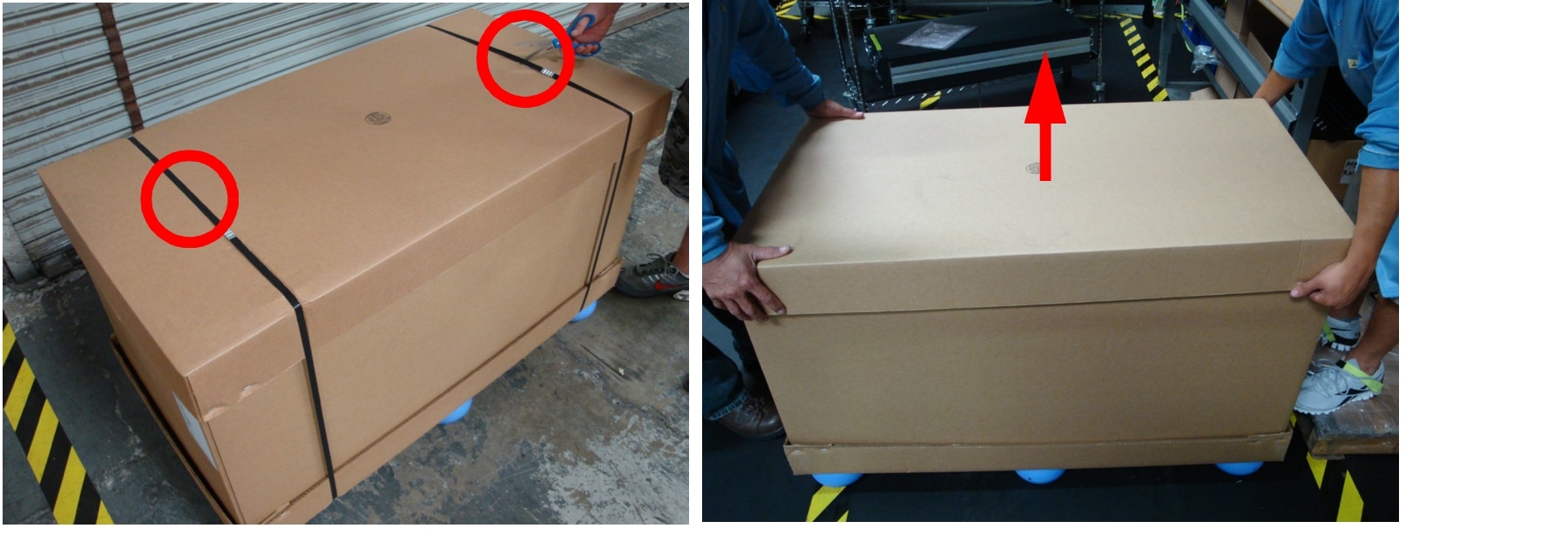
Step 1 ![]() Carefully cut the straps holding the box closed and remove the outer lid.
Carefully cut the straps holding the box closed and remove the outer lid.
Figure 2-1 Opening the Outer Box
Step 2 ![]() Open the accessory boxes and make sure that all expected contents are present.
Open the accessory boxes and make sure that all expected contents are present.
Figure 2-2 Accessory Boxes and Contents (Example)
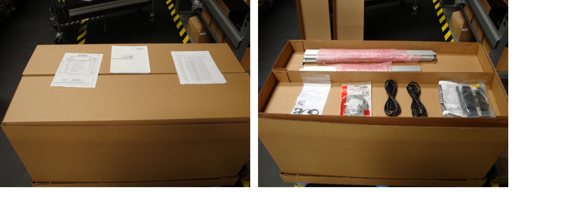
The accessory boxes should contain:
•![]() Rack-mounting hardware:
Rack-mounting hardware:
–![]() Two (2) rail assemblies
Two (2) rail assemblies
–![]() Eight (8) large screws for securing the rails to the rack
Eight (8) large screws for securing the rails to the rack
–![]() Two (2) chassis rack-mount "ears", one left and one right
Two (2) chassis rack-mount "ears", one left and one right
–![]() Four (4) screws for attaching the chassis "ears" to the unit
Four (4) screws for attaching the chassis "ears" to the unit
–![]() Two (2) cage nuts and two (2) bolts for securing the unit to the rack
Two (2) cage nuts and two (2) bolts for securing the unit to the rack
•![]() Two (2) power cables
Two (2) power cables
•![]() Disposable ESD strap
Disposable ESD strap
•![]() Serial cable (CPS-SS-4RU only)
Serial cable (CPS-SS-4RU only)
•![]() Any additional items that may have been ordered, such as SAS cables
Any additional items that may have been ordered, such as SAS cables
Step 3 ![]() Remove the accessory boxes from the outer packaging.
Remove the accessory boxes from the outer packaging.
Step 4 ![]() Remove the disk boxes from the outer packaging.
Remove the disk boxes from the outer packaging.
Figure 2-3 Removing Disk Boxes from Outer Box

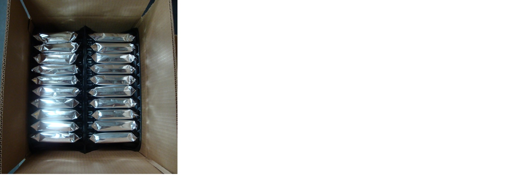
Step 5 ![]() Open the disk boxes and make sure that the proper number of disk drives is included.
Open the disk boxes and make sure that the proper number of disk drives is included.
Figure 2-4 Contents of a Disk Box (Example)
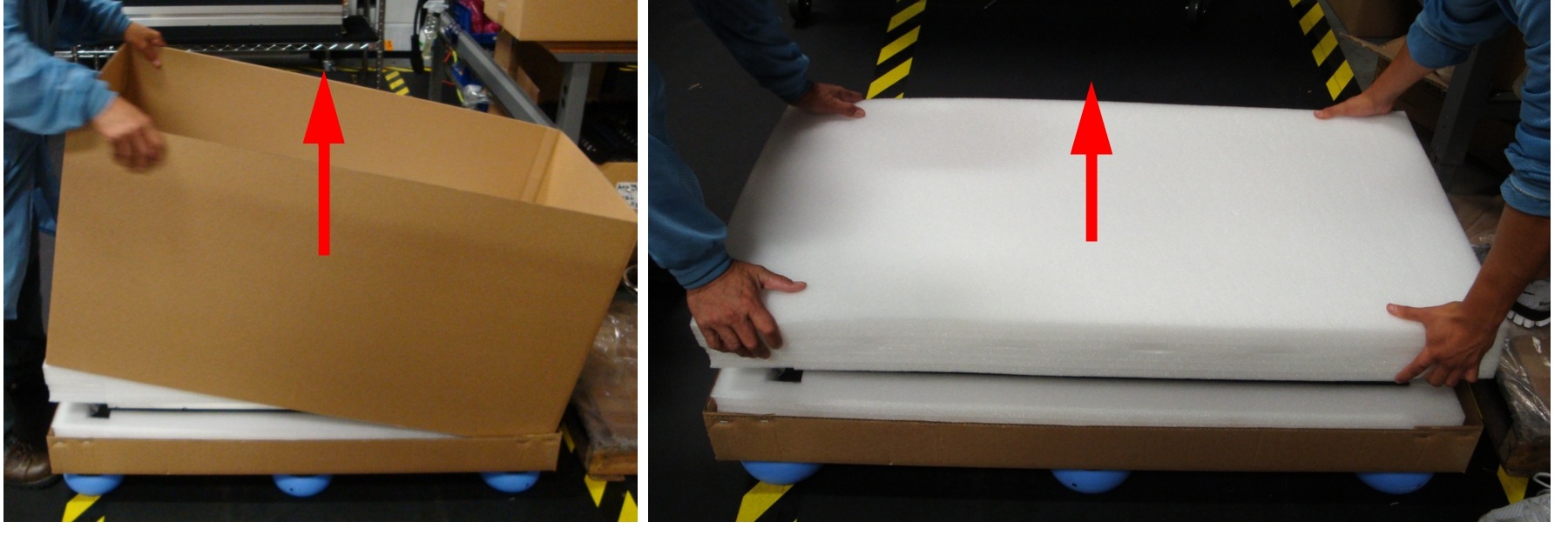
Step 6 ![]() Remove the outer packaging sleeve and the foam lid covering the CPS-SS-4RU or CPS-SS-4RU-EX unit.
Remove the outer packaging sleeve and the foam lid covering the CPS-SS-4RU or CPS-SS-4RU-EX unit.
Figure 2-5 Removing the Outer Packaging Sleeve and Foam Lid
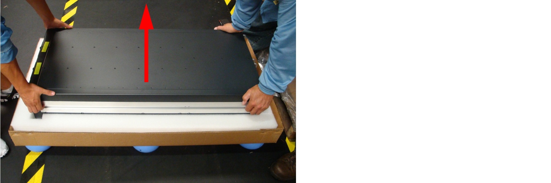
Step 7 ![]() With the help of a second person, carefully lift the unit out of the packaging.
With the help of a second person, carefully lift the unit out of the packaging.
Figure 2-6 Removing the Unit From the Box
The packaging that the unit ships in is reusable and should be retained for future re-shipment. Be sure to keep all packaging components.
Preparing the Units
Perform the following procedure to prepare the CPS-SS-4RU and CPS-SS-4RU-EX for installation:
Procedure
Step 1 ![]() Remove the two Power Supply Units (PSUs) and one or two RAID Controllers/Expansion Controllers from the unit:
Remove the two Power Supply Units (PSUs) and one or two RAID Controllers/Expansion Controllers from the unit:
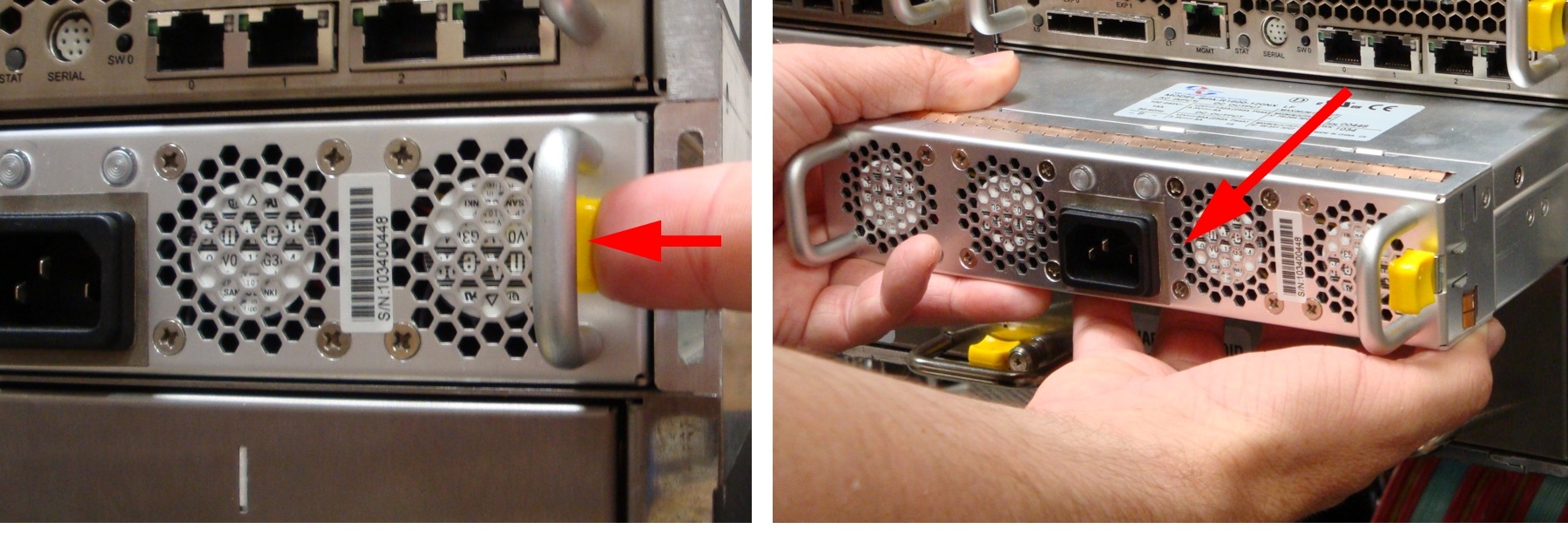
a. ![]() PSU—Press the spring lock tab away from the edge of the PSU, then carefully remove the PSU from the unit. Support the weight of the PSU with your free hand while removing it.
PSU—Press the spring lock tab away from the edge of the PSU, then carefully remove the PSU from the unit. Support the weight of the PSU with your free hand while removing it.
Figure 2-7 Removing the PSUs From the CPS-SS-4RU or CPS-SS-4RU-EX
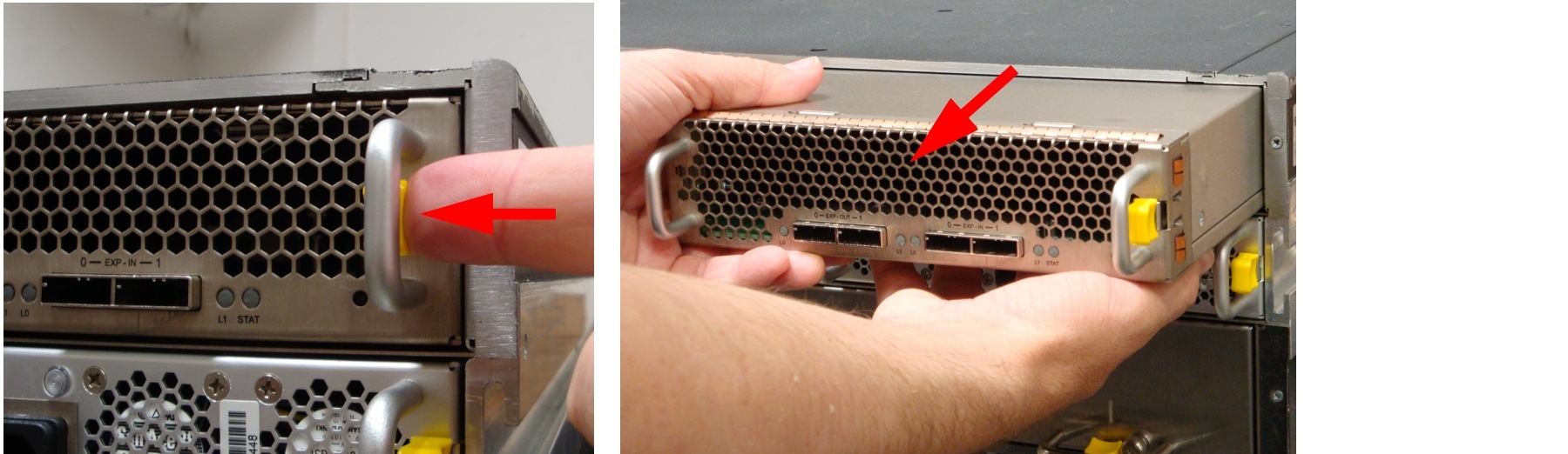
b. ![]() RAID/Expansion Controller—Press the spring lock tab away from the edge of the controller, then carefully remove it from the unit. Support the weight of the controller with your free hand while removing it.
RAID/Expansion Controller—Press the spring lock tab away from the edge of the controller, then carefully remove it from the unit. Support the weight of the controller with your free hand while removing it.
Figure 2-8 Removing the RAID Controllers From the CPS-SS-4RU
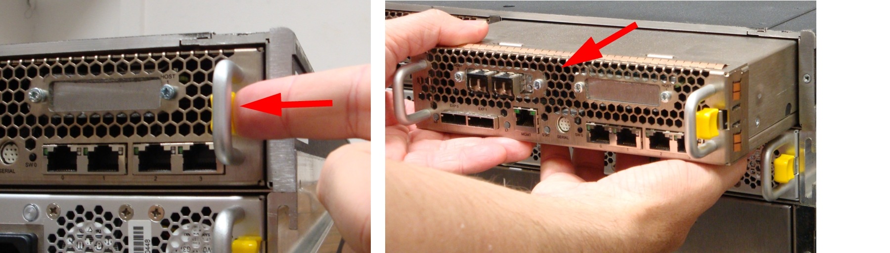
Figure 2-9 Removing the Expansion Controllers From the CPS-SS-4RU-EX

Note ![]() For dual-controller units, remember to put each controller back into the same bay from which you removed it. It may be helpful to label them "Left" and "Right" before removing them.
For dual-controller units, remember to put each controller back into the same bay from which you removed it. It may be helpful to label them "Left" and "Right" before removing them.
Set the PSUs and RAID/Expansion Controllers aside.
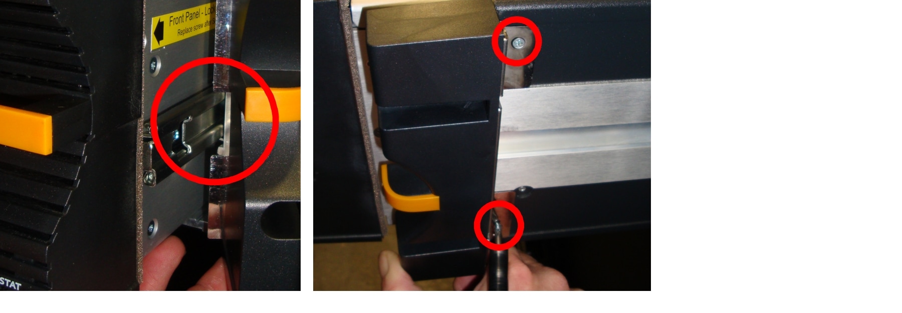
Step 2 ![]() Attach the chassis rack-mount "ears" to the front of the unit using the supplied screws.
Attach the chassis rack-mount "ears" to the front of the unit using the supplied screws.
For CPS-SS-4RU and CPS-SS-4RU-EX, extend the right and left drawers slightly before attaching the ears.
Figure 2-10 Unlocking and Extending the Drawers on the CPS-SS-4RU or CPS-SS-4RU-EX
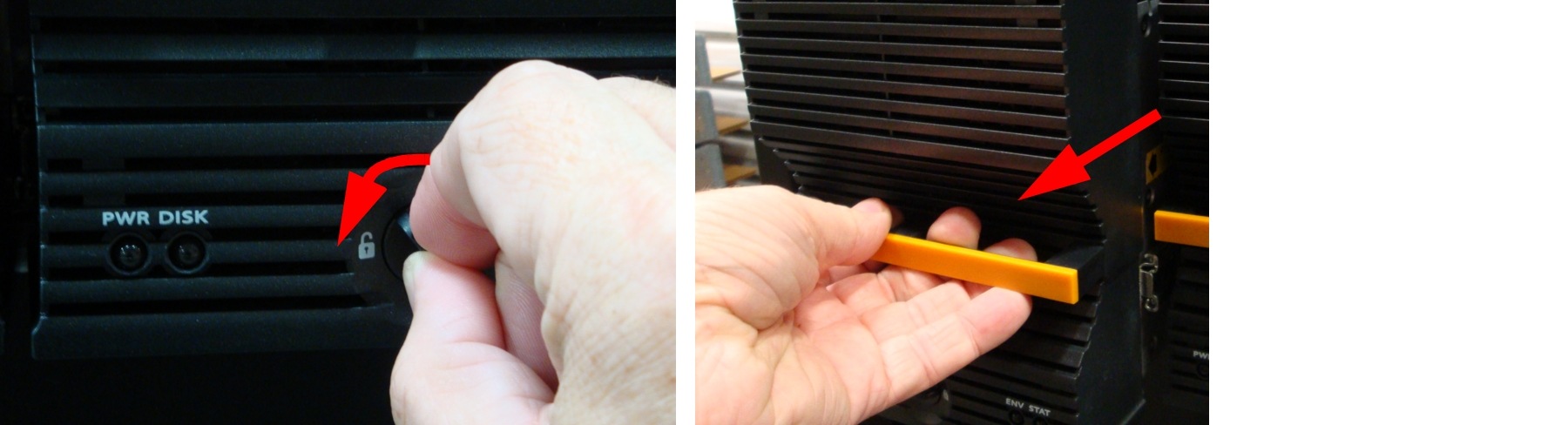
Figure 2-11 Attaching the Chassis Rack-Mount "Ears" to the CPS-SS-4RU or CPS-SS-4RU-EX
Close and lock the drawers again once the ears are attached.
 Feedback