- Preface
- Cisco Video Surveillance Storage System Component Overview
- Unpacking and Preparing Components
- Rack Mounting Components
- Cabling & Power-up Procedures
- Field-Replaceable Units
- CPS-SS-4RU Technical Specifications
- CIVS-SS-4RU-84000 Technical Specifications
- CPS-SS-2RU Technical Specifications
- CPS-SS-4RU-EX Technical Specifications
- Index
Cisco Video Surveillance Storage System Hardware Installation Guide
Bias-Free Language
The documentation set for this product strives to use bias-free language. For the purposes of this documentation set, bias-free is defined as language that does not imply discrimination based on age, disability, gender, racial identity, ethnic identity, sexual orientation, socioeconomic status, and intersectionality. Exceptions may be present in the documentation due to language that is hardcoded in the user interfaces of the product software, language used based on RFP documentation, or language that is used by a referenced third-party product. Learn more about how Cisco is using Inclusive Language.
- Updated:
- March 2, 2012
Chapter: Cisco Video Surveillance Storage System Component Overview
Cisco Video Surveillance Storage System Component Overview
This chapter provides an Overview of the CPS-SS-4RU and CPS-SS-4RU-EX Cisco Video Surveillance Storage System components.
Overview of the CPS-SS-4RU and CPS-SS-4RU-EX
Front Panel (Both Units)
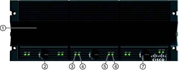
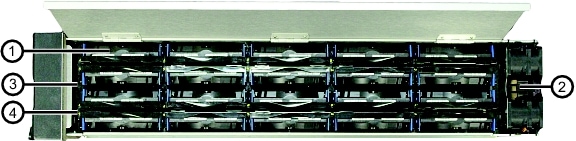
Figure 1-1 CPS-SS-4RU and CPS-SS-4RU-EX Front Panel
|
|
Drawer Front Fan Assembly |
|
Environment LED |
|
|
Active Drive Drawer |
|
Status LED |
|
|
Power LED |
|
Drawer Lock |
|
|
Disk LED |
||
Field-Replaceable Modules
Drawer Front Assembly w/ Fan—Each assembly can be field-replaced in the event of a fan failure by removing a screw on each side of the drive drawer (see Front Drive Drawer Fan Assembly).
Other Modules
Active Drive Drawers (3)—Each drawer can hold up to 20 3.5" disk drives, for a total of up to 60 drives in the unit. Can only be replaced by a fully-trained Service Engineer.
LEDs
Each drive drawer has four LEDs:
•![]() Power LED (PWR)—Indicates the status of power to the components in the drawer. Green indicates that all power levels are within specifications. Red indicates that one or more power levels are outside of specifications. The Environmental Information page (under System Information) in the graphical user interface (GUI) displays details (see the Software Manual).
Power LED (PWR)—Indicates the status of power to the components in the drawer. Green indicates that all power levels are within specifications. Red indicates that one or more power levels are outside of specifications. The Environmental Information page (under System Information) in the graphical user interface (GUI) displays details (see the Software Manual).
If the PWR LED on the left drive drawer is amber and all other front panel LEDs are off, this means that the unit has been powered down through the graphical user interface (GUI).
•![]() Disk LED (DSK)—Indicates the status of the disk drives in the drawer. Green indicates that all disk drives are operating within specifications. Red indicates that one or more disk faults have been detected. The Disk Drives page (under RAID Information) in the graphical user interface (GUI) displays details (see the Software Manual).
Disk LED (DSK)—Indicates the status of the disk drives in the drawer. Green indicates that all disk drives are operating within specifications. Red indicates that one or more disk faults have been detected. The Disk Drives page (under RAID Information) in the graphical user interface (GUI) displays details (see the Software Manual).
•![]() Environment LED (ENV)—Indicates the temperature and fan status for the drawer. Green indicates that the drawer temperature is within specifications and that all fans are operating properly. Red indicates that the temperature exceeds specifications or that one or more fans are not operating properly. The Environmental Information page (under System Information) in the graphical user interface (GUI) displays details (see the Software Manual).
Environment LED (ENV)—Indicates the temperature and fan status for the drawer. Green indicates that the drawer temperature is within specifications and that all fans are operating properly. Red indicates that the temperature exceeds specifications or that one or more fans are not operating properly. The Environmental Information page (under System Information) in the graphical user interface (GUI) displays details (see the Software Manual).
•![]() Status LED (STAT)—Indicates overall status. Green indicates that the unit is operating within specification. Amber indicates that the drawer is unlocked. Red indicates a fault in the unit, which could be any of the following:
Status LED (STAT)—Indicates overall status. Green indicates that the unit is operating within specification. Amber indicates that the drawer is unlocked. Red indicates a fault in the unit, which could be any of the following:
–![]() A Power Supply Unit issue with the fan, temperature, or voltage
A Power Supply Unit issue with the fan, temperature, or voltage
–![]() A RAID Controller issue with the temperature, voltage, battery, firmware, or other hardware (CPS-SS-4RU only)
A RAID Controller issue with the temperature, voltage, battery, firmware, or other hardware (CPS-SS-4RU only)
–![]() A drawer voltage issue
A drawer voltage issue
The Environmental Information page (under System Information) in the graphical user interface (GUI) displays details (see the Software Manual).
Other Items
Drawer Lock—Secures the drive drawer in place. When this lock is disengaged, the STAT LED turns amber.
Rear Panel (CPS-SS-4RU)
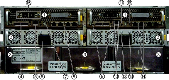
Figure 1-2 CPS-SS-4RU Rear Panel
|
|
RAID Controllers |
|
SAS port status LEDs |
|
|
Power Supply Units (PSUs) |
|
MGMT port status/activity LEDs |
|
|
Interconnect Service Modules (ISMs) |
|
Controller status (STAT) LED |
|
|
SAS ports (4) |
|
PSU status LED |
|
|
Management (MGMT) ports (2) |
|
PSU fan status LED |
|
|
Power connector |
|
iSCSI port status/activity LEDs |
|
|
Serial ports (2) |
|
Host ports (see Figure 1-3) |
|
|
iSCSI ports (8) |
|
SW0 switch |
Field-Replaceable Modules
The rear panel field-replaceable modules are:
•![]() RAID Controller(s) (1 or 2)—Each unit can be field-replaced in the event of failure (see RAID Controllers). RAID Controllers are designated Controller 0 (left) and Controller 1 (right) in the graphical user interface (GUI) (see the Software Manual).
RAID Controller(s) (1 or 2)—Each unit can be field-replaced in the event of failure (see RAID Controllers). RAID Controllers are designated Controller 0 (left) and Controller 1 (right) in the graphical user interface (GUI) (see the Software Manual).

Note ![]() In single-controller units, the second slot contains a back plate which helps regulate air flow.
In single-controller units, the second slot contains a back plate which helps regulate air flow.
•![]() Power Supply Units (PSUs) (2)—Each unit can be field-replaced in the event of a PSU or PSU fan failure (see Power Supply Units (PSUs)).
Power Supply Units (PSUs) (2)—Each unit can be field-replaced in the event of a PSU or PSU fan failure (see Power Supply Units (PSUs)).
Other Modules
Interconnect Service Modules (ISMs) (3)—Can only be replaced by a fully-trained Service Engineer.
Connectors
The rear panel connectors are:
•![]() Two SAS ports (EXP 0 and EXP 1) per RAID Controller—Mini-SAS 26 pin I-Pass (8088) expansion connectors, each with four 3GB/s SAS links
Two SAS ports (EXP 0 and EXP 1) per RAID Controller—Mini-SAS 26 pin I-Pass (8088) expansion connectors, each with four 3GB/s SAS links
•![]() One Management port (MGMT) per RAID Controller—Ethernet 10/100 dedicated management port (RJ45) for web-based configuration
One Management port (MGMT) per RAID Controller—Ethernet 10/100 dedicated management port (RJ45) for web-based configuration
•![]() Power (2)—220-240VAC, 47-63Hz
Power (2)—220-240VAC, 47-63Hz
•![]() One SERIAL port per RAID Controller—Mini-DIN serial port for low-level reporting (Support use only)
One SERIAL port per RAID Controller—Mini-DIN serial port for low-level reporting (Support use only)
•![]() Four iSCSI ports (NETWORK PORTS 0 through 3) per RAID Controller—1Gb/s Ethernet ports (RJ45s) for iSCSI. If a host port option (see Host Port Options) is installed, only ports 0 and 1 are usable.
Four iSCSI ports (NETWORK PORTS 0 through 3) per RAID Controller—1Gb/s Ethernet ports (RJ45s) for iSCSI. If a host port option (see Host Port Options) is installed, only ports 0 and 1 are usable.
LEDs
The rear panel LEDs are:
•![]() SAS port LEDs (L0 and L1)—Indicate the connection status for each SAS port. Green indicates that the SAS cable is properly connected. Flashing amber indicates that the cable is improperly connected. If no cable is connected, this LED is off.
SAS port LEDs (L0 and L1)—Indicate the connection status for each SAS port. Green indicates that the SAS cable is properly connected. Flashing amber indicates that the cable is improperly connected. If no cable is connected, this LED is off.
•![]() Management port LEDs (activity and speed)—The left LED flashes green when there is port activity. The right LED lights up green when there is a 100Mb/s connection. When there is only a 10Mb/s connection, the right LED is off.
Management port LEDs (activity and speed)—The left LED flashes green when there is port activity. The right LED lights up green when there is a 100Mb/s connection. When there is only a 10Mb/s connection, the right LED is off.
•![]() Controller status LED (STAT)—Indicates the status of the RAID Controller:
Controller status LED (STAT)—Indicates the status of the RAID Controller:
–![]() Solid blue indicates that the controller is operating within specifications and that there is no user data in the cache.
Solid blue indicates that the controller is operating within specifications and that there is no user data in the cache.
–![]() Solid green indicates that the controller is operating within specifications and that there is user data in the cache, which will be retained in flash memory upon power-down and then restored when the unit is powered up again.
Solid green indicates that the controller is operating within specifications and that there is user data in the cache, which will be retained in flash memory upon power-down and then restored when the unit is powered up again.
–![]() Flashing red (once per second) indicates that the controller is offline due to a fault being detected.
Flashing red (once per second) indicates that the controller is offline due to a fault being detected.
–![]() Flashing green (twice per second) indicates that the controller is operating in battery-backed mode and is backing up cached data to flash memory. This can take several minutes.
Flashing green (twice per second) indicates that the controller is operating in battery-backed mode and is backing up cached data to flash memory. This can take several minutes.
–![]() Alternating blue and red indicates that the controller is booting in Emergency mode (see Switches).
Alternating blue and red indicates that the controller is booting in Emergency mode (see Switches).
•![]() PSU LED—Indicates the status of power. Green indicates that the 12V and 3V3 outputs are within specification. Red indicates that one or the other, or both, are outside of specified limits. Orange indicates that the PSU is in standby mode.
PSU LED—Indicates the status of power. Green indicates that the 12V and 3V3 outputs are within specification. Red indicates that one or the other, or both, are outside of specified limits. Orange indicates that the PSU is in standby mode.
•![]() FAN LED—Indicates the status of the PSU fans. Green indicates that all fans are operating within specifications. Red indicates that one or more fans are either running too slowly or have failed. When the PSU is in standby mode, this LED is off.
FAN LED—Indicates the status of the PSU fans. Green indicates that all fans are operating within specifications. Red indicates that one or more fans are either running too slowly or have failed. When the PSU is in standby mode, this LED is off.
•![]() iSCSI port LEDs (activity and status)—For 1Gb/s and 100Mb/s connections, the left LED illuminates green, and both LEDs flash green when there is activity. For 10Mb/s connections, the left LED remains off, and the right LED flashes green where there is activity.
iSCSI port LEDs (activity and status)—For 1Gb/s and 100Mb/s connections, the left LED illuminates green, and both LEDs flash green when there is activity. For 10Mb/s connections, the left LED remains off, and the right LED flashes green where there is activity.
Switches
SW0 Switch—This switch can be used to turn the RAID Controller off or on, boot the controller in Emergency mode, or silence an audible alarm.
With the unit powered on:
•![]() Briefly press the SW0 switch to silence the audible alarm. This can also be done via the graphical user interface (GUI) (see the Software Manual).
Briefly press the SW0 switch to silence the audible alarm. This can also be done via the graphical user interface (GUI) (see the Software Manual).
•![]() Press and hold the SW0 switch for 8 seconds to power down the RAID Controllers. If there is data in the cache, it will be stored in flash memory. This is the same as performing a System Shutdown via the graphical user interface (GUI) (see the Software Manual). On dual-controller systems, both SW0 switches must be held simultaneously for 8 seconds.
Press and hold the SW0 switch for 8 seconds to power down the RAID Controllers. If there is data in the cache, it will be stored in flash memory. This is the same as performing a System Shutdown via the graphical user interface (GUI) (see the Software Manual). On dual-controller systems, both SW0 switches must be held simultaneously for 8 seconds.
With the unit powered off:
•![]() Press and hold the SW0 switch on either RAID Controller for 4 seconds to power up the unit. Release the SW0 switch to boot normally.
Press and hold the SW0 switch on either RAID Controller for 4 seconds to power up the unit. Release the SW0 switch to boot normally.
•![]() Continue pressing the SW0 switch after the unit powers up to put the RAID Controllers into Emergency mode (see the Software Manual). Emergency mode is indicated by the controller status LED alternating between blue and red (see LEDs).
Continue pressing the SW0 switch after the unit powers up to put the RAID Controllers into Emergency mode (see the Software Manual). Emergency mode is indicated by the controller status LED alternating between blue and red (see LEDs).
Host Port Options
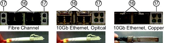
Figure 1-3 Host Port Options
|
|
Ports (Fibre Channel or 10Gb iSCSI) |
|
Port LEDs |
The two host ports are either of the following:
•![]() Two Fibre Channel ports (0 and 1) per RAID Controller—8Gb/s Fibre Channel optical SFPs on a single PCIe card
Two Fibre Channel ports (0 and 1) per RAID Controller—8Gb/s Fibre Channel optical SFPs on a single PCIe card
OR
•![]() Two 10Gb iSCSI (10GbE) ports (0 and 1) per Controller—10Gb/s Ethernet optical SFPs or copper SFP sockets for iSCSI on a single PCIe card.
Two 10Gb iSCSI (10GbE) ports (0 and 1) per Controller—10Gb/s Ethernet optical SFPs or copper SFP sockets for iSCSI on a single PCIe card.
The host port LEDs operate in either of the following ways, depending on the host port option:
•![]() Fibre Channel port LEDs (speed and activity)—The upper LED is orange when there is a 2Gb/s connection and green when there is a 4Gb/s connection. The lower LED flashes yellow for data activity, but also lights up yellow when there is an 8Gb/s connection. When there is an 8Gb/s connection, the upper LED is off. During the power-up sequence, both Fibre Channel port LEDs are solid yellow. If both LEDs are flashing yellow, the Fibre Channel connection has been lost.
Fibre Channel port LEDs (speed and activity)—The upper LED is orange when there is a 2Gb/s connection and green when there is a 4Gb/s connection. The lower LED flashes yellow for data activity, but also lights up yellow when there is an 8Gb/s connection. When there is an 8Gb/s connection, the upper LED is off. During the power-up sequence, both Fibre Channel port LEDs are solid yellow. If both LEDs are flashing yellow, the Fibre Channel connection has been lost.
OR
•![]() 10Gb iSCSI port LEDs (connection and activity)—For each 10Gb iSCSI connection (left and right), the lower LED lights up green when there is a 10GbE connection and the upper LED flashes green when there is activity. When there is no connection, these LEDs are off.
10Gb iSCSI port LEDs (connection and activity)—For each 10Gb iSCSI connection (left and right), the lower LED lights up green when there is a 10GbE connection and the upper LED flashes green when there is activity. When there is no connection, these LEDs are off.
Rear Panel (CPS-SS-4RU-EX)
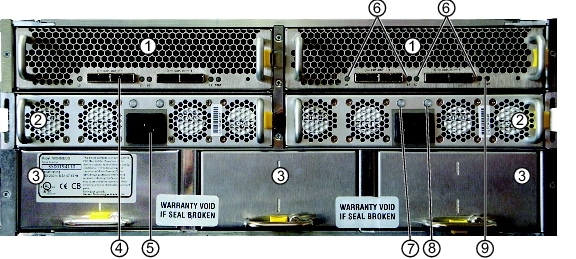
Figure 1-4 CPS-SS-4RU-EX Rear Panel
Field-Replaceable Modules
The rear panel field-replaceable modules are:
•![]() Expansion Controllers (2)—Each unit can be field-replaced in the event of failure (see Expansion Controllers).
Expansion Controllers (2)—Each unit can be field-replaced in the event of failure (see Expansion Controllers).
•![]() Power Supply Units (PSUs) (2)—Each unit can be field-replaced in the event of a PSU or PSU fan failure (see Power Supply Units (PSUs)).
Power Supply Units (PSUs) (2)—Each unit can be field-replaced in the event of a PSU or PSU fan failure (see Power Supply Units (PSUs)).
Other Modules
Interconnect Service Modules (ISMs) (3)—Can only be replaced by a fully-trained Service Engineer.
Connectors
The rear panel connectors are:
•![]() Four SAS ports (EXP IN 0 and 1, EXP OUT 0 and 1) per Expansion Controller—Mini-SAS 26 pin I-Pass (8088) expansion connectors, each with four 3Gb/s SAS links (EXP IN usable, EXP OUT reserved for future use)
Four SAS ports (EXP IN 0 and 1, EXP OUT 0 and 1) per Expansion Controller—Mini-SAS 26 pin I-Pass (8088) expansion connectors, each with four 3Gb/s SAS links (EXP IN usable, EXP OUT reserved for future use)
•![]() Power (2)—220-240VAC, 47-63Hz
Power (2)—220-240VAC, 47-63Hz
LEDs
The rear panel LEDs are:
•![]() SAS port LEDs (EXP IN L0 and L1, EXP OUT L0 and L1)—Indicate the connection status for each SAS port. Green indicates that the SAS cable is properly connected. Flashing amber indicates that the cable is improperly connected. If no cable is connected, this LED is off.
SAS port LEDs (EXP IN L0 and L1, EXP OUT L0 and L1)—Indicate the connection status for each SAS port. Green indicates that the SAS cable is properly connected. Flashing amber indicates that the cable is improperly connected. If no cable is connected, this LED is off.
•![]() PSU Status LED—Indicates the status of power. Green indicates that the 12V and 3V3 outputs are within specification. Red indicates that one or the other, or both, are outside of specified limits. Orange indicates that the PSU is in standby mode.
PSU Status LED—Indicates the status of power. Green indicates that the 12V and 3V3 outputs are within specification. Red indicates that one or the other, or both, are outside of specified limits. Orange indicates that the PSU is in standby mode.
•![]() PSU Fan LED—Indicates the status of the PSU fans. Green indicates that all fans are operating within specifications. Red indicates that one or more fans are either running too slowly or have failed. When the PSU is in standby mode, this LED is off.
PSU Fan LED—Indicates the status of the PSU fans. Green indicates that all fans are operating within specifications. Red indicates that one or more fans are either running too slowly or have failed. When the PSU is in standby mode, this LED is off.
•![]() Controller status LED (STAT)—Indicates the status of the Expansion Controller:
Controller status LED (STAT)—Indicates the status of the Expansion Controller:
–![]() Flashing green indicates that the controller is operating within specifications.
Flashing green indicates that the controller is operating within specifications.
–![]() Flashing red indicates that the controller is restarting.
Flashing red indicates that the controller is restarting.
–![]() Solid red indicates that there is an issue with the Expansion Controller. The Environmental Information page (under System Information) in the graphical user interface (GUI) displays details (see the Software Manual).
Solid red indicates that there is an issue with the Expansion Controller. The Environmental Information page (under System Information) in the graphical user interface (GUI) displays details (see the Software Manual).
Drawer Interior (Both Units)
Figure 1-5 CPS-SS-4RU and CPS-SS-4RU-EX Drawer Interior
|
|
Disk drives |
|
Disk drive rails |
|
|
Rear fan assembly |
|
Drive status LEDs |
Field-Replaceable Modules
The field-replaceable modules inside the drive drawers are:
•![]() Disk Drives—Up to 20 3.5" disk drives in each drawer. Disk drives can be field-replaced in the event of failure (see Disk Drives).
Disk Drives—Up to 20 3.5" disk drives in each drawer. Disk drives can be field-replaced in the event of failure (see Disk Drives).
•![]() Rear Fan Pack—Dual-fan assembly located at the rear of each drawer. Can be field-replaced in the event of failure (see Rear Drive Drawer Fan Assembly).
Rear Fan Pack—Dual-fan assembly located at the rear of each drawer. Can be field-replaced in the event of failure (see Rear Drive Drawer Fan Assembly).
Other Modules
Drive Guides—Align with plastic rails on disk drives to guide installation. These are integral to the drive drawer and cannot be individually replaced (see Front Panel (Both Units)).
LEDs
Drive status—One for each disk drive slot. Solid green indicates that the disk is operating within specifications and is not currently being accessed. Flashing green indicates disk activity. Red indicates that a disk fault has been detected and that the disk is not currently being used by the system. For disk drive slots where no disk drive is installed, this LED is off.
 Feedback