- New and Changed Information
- Preface
- Documentation Roadmap
- Introduction
- Getting Started
- Licensing Requirements
- Using configTOOL
- Using perfectHOST
- Ports and Protocols
- KNX Deployment
- Getting Started with Mediator Web Client
- Managing Events
- Managing Security
- Managing Trends
- Managing Schedules
- Customizing HTML Pages with Web Express
- Energywise Manager
- Using Enterprise Navigation Tree
- Global Setpoints
- ADR Client
Energywise Manager
This chapter describes how to configure and view the Energywise service and energy consumption using configTOOL and the Mediator.
This chapter includes the following topics:
•![]() Requirements for Energywise Manager
Requirements for Energywise Manager
•![]() Configuring Energywise Manager
Configuring Energywise Manager
About Energywise Manager
Cisco Energywise is a Cisco IOS-based software application that enables Cisco networks to control and perform energy management. The Energywise software enables customers to monitor, control, and report on the energy use of building equipment and IT devices using an Energywise-enabled network. More importantly, Energywise enables customers to set dynamic power policies that enable them to save money and reduce greenhouse gas emissions when equipment is not in use. Energywise is part of Cisco IOS within Cisco Catalyst switches, ISR routers, and other equipment. A software toolkit is available for customers to communicate with a Cisco network to monitor and control Energywise information.
Energywise gives customers the ability to monitor and control AC-powered devices like smart power distribution units, building systems, and PCs. It also enables customers to control the power consumption of networking equipment including routers, LAN switches, and connected Power over Ethernet (PoE) devices, such as phones, access points, IP security cameras, and door access equipment. Energywise can orchestrate power control across a series of devices in the network.
In an Energywise network, Energywise monitors and manages the power usage of powered devices, Cisco devices in a domain and the end points connected to them. An end point can be a device connected to the network, such as an IP phone, access point, or PC. An entity refers to a domain member or an end point. You can configure policies, referred to as recurring events, to manage the power usage (See Figure 14-1).
Figure 14-1 Energywise Network
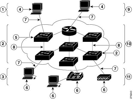
•![]() Management stations—Control applications and devices that use Energywise to monitor and manage the power usage of domain members and end points. Management stations also send queries.
Management stations—Control applications and devices that use Energywise to monitor and manage the power usage of domain members and end points. Management stations also send queries.
•![]() Domain members—Cisco switches, routers, and network devices that use power. They forward messages across the network to form an Energywise domain with other Cisco devices and end points. They also forward and reply to queries from the management station and from other domain members and aggregate power-usage information from the end points.
Domain members—Cisco switches, routers, and network devices that use power. They forward messages across the network to form an Energywise domain with other Cisco devices and end points. They also forward and reply to queries from the management station and from other domain members and aggregate power-usage information from the end points.
A domain is treated as one unit of power management and is similar to a network-management community.
•![]() End points—Devices that use power. They only respond to queries.
End points—Devices that use power. They only respond to queries.
Domain members and end points can receive power from an AC power source, a DC power source, or a power supply. Power over Ethernet (PoE) domain members and end points can also receive power from PoE switches or Cisco EtherSwitch service modules. For example, IP phones and access points connected to a PoE switch receive power from the switch.
Requirements for Energywise Manager
By default, Energywise is disabled on Cisco network devices. All domain members must run either:
•![]() Energywise Phase 1
Energywise Phase 1
•![]() Energywise Phase 2 or later
Energywise Phase 2 or later

Note ![]() Energywise Phase 2 is not backward-compatible with Energywise Phase 1.
Energywise Phase 2 is not backward-compatible with Energywise Phase 1.
Phase 2 implementation of Energywise on the Mediator supports two modes of communication:
•![]() Using SNMP
Using SNMP
•![]() Using Energywise Query/Native method
Using Energywise Query/Native method
Note ![]() For Energywise Query/Native method, you need Energywise Phase2 or above running on the switches. You do not need SNMP enabled on the Mediator. You can get data for the complete Energywise domain by configuring one switch on the Mediator.
For Energywise Query/Native method, you need Energywise Phase2 or above running on the switches. You do not need SNMP enabled on the Mediator. You can get data for the complete Energywise domain by configuring one switch on the Mediator.
We recommend that before you begin configuring the Energywise service on the Mediator, you perform the following tasks:
•![]() Enable Energywise
Enable Energywise
•![]() Create an Energywise domain on the switch
Create an Energywise domain on the switch
•![]() Add switches to the domain
Add switches to the domain
•![]() Configure POE / non-POE devices connected to the switches
Configure POE / non-POE devices connected to the switches
•![]() Verify the Energywise domain information on the switch
Verify the Energywise domain information on the switch
For more information on Energywise Phase 1, go to http://www.cisco.com/en/US/docs/switches/lan/energywise/phase1/ios/configuration/guide/ew_v1.html
For more information on Energywise Phase 2, go to
https://www.cisco.com/en/US/docs/switches/lan/energywise/phase2/ios/configuration/guide/ew_v2.html
For more documentation on Energywise, go to http://energywise.cisco.com.
Configuring Energywise Manager
Note![]() •
•![]() If you are configuring the Energywise service on the Mediator to run on the Native mode, you do not need SNMP enabled on the Mediator.
If you are configuring the Energywise service on the Mediator to run on the Native mode, you do not need SNMP enabled on the Mediator.
Note![]() •
•![]() If you are configuring the Energywise service on the Mediator, to run on the SNMP mode, ensure that you have enabled SNMP on the switch.
If you are configuring the Energywise service on the Mediator, to run on the SNMP mode, ensure that you have enabled SNMP on the switch.
To configure SNMP, in the node tree pane of the configTOOL window, right-click the network node, and choose Add from the drop-down list. The Available Devices dialog box appears. Choose SNMP (SNMP) from the list, and then click OK.
When you configure SNMP on an Energywise switch, the Energywise MIB elements are discovered and created at the following location: /services/network/SNMP/Remote Agents/EW Switch. These MIB elements provide the flexibility to control individual Energywise entities.
To add the Energywise Manager using configTOOL, perform the following steps:
Step 1 ![]() Start the configTOOL and connect to a Mediator (see Accessing Mediators Using configTOOL, page 4-11 for further information).
Start the configTOOL and connect to a Mediator (see Accessing Mediators Using configTOOL, page 4-11 for further information).
The configTOOL window appears.
Step 2 ![]() In the node tree pane of the configTOOL window, right-click the services node, and choose Add from the drop-down list.
In the node tree pane of the configTOOL window, right-click the services node, and choose Add from the drop-down list.
The Available Devices dialog box appears.
Step 3 ![]() In the Available Devices dialog box, choose Energywise Manager (Energywise Manager) from the list, and then click OK.
In the Available Devices dialog box, choose Energywise Manager (Energywise Manager) from the list, and then click OK.
A new child node, Energywise Manager_1, appears under the Services node in the node tree pane.
Step 4 ![]() In the node tree pane, right-click the Energywise Manager_1 node, and choose Add from the drop-down list to add a domain.
In the node tree pane, right-click the Energywise Manager_1 node, and choose Add from the drop-down list to add a domain.
The Available Devices dialog box appears.
Step 5 ![]() In the Available Devices dialog box, click the Build EW Domain hierarchy (EW Domain), and then click OK.
In the Available Devices dialog box, click the Build EW Domain hierarchy (EW Domain), and then click OK.
A new child node, EW Domain, appears under the Energywise Manager_1 node in the node tree pane.
Step 6 ![]() In the Name text box, enter the same Energywise domain as specified on the switch.
In the Name text box, enter the same Energywise domain as specified on the switch.
For example, if the Energywise domain configured on the switch is A.B.C, configure the Energywise domain hierarchy on the Mediator as follows:
a. ![]() In the Name text box, enter A.
In the Name text box, enter A.
b. ![]() In the node tree pane, right-click the A node, and choose Add from the drop-down list. The Available Devices dialog box appears.
In the node tree pane, right-click the A node, and choose Add from the drop-down list. The Available Devices dialog box appears.
c. ![]() In the Available Devices dialog box, click Build EW Domain hierarchy (EW Domain), and then click OK.
In the Available Devices dialog box, click Build EW Domain hierarchy (EW Domain), and then click OK.
A new child node, EW Domain, appears under the A node in the node tree pane.
d. ![]() In the Name text box, enter B.
In the Name text box, enter B.
e. ![]() In the node tree pane, right-click the B node, and choose Add from the drop-down list. The Available Devices dialog box appears.
In the node tree pane, right-click the B node, and choose Add from the drop-down list. The Available Devices dialog box appears.
f. ![]() In the Available Devices dialog box, click Build EW Domain hierarchy (EW Domain), and then click OK.
In the Available Devices dialog box, click Build EW Domain hierarchy (EW Domain), and then click OK.
A new child node, EW Domain, appears under the B node in the node tree pane.
g. ![]() In the Name text box, enter C.
In the Name text box, enter C.
Therefore, an Energywise domain A.B.C on the switch translates to a hierarchical domain structure on the Mediator.
Step 7 ![]() In the node tree pane, right-click the C node, and choose Add from the drop-down list to add a switch.
In the node tree pane, right-click the C node, and choose Add from the drop-down list to add a switch.
Note ![]() Before adding a switch, ensure that at least one domain is configured under Energywise Manager because a switch cannot be directly added to Energywise Manager.
Before adding a switch, ensure that at least one domain is configured under Energywise Manager because a switch cannot be directly added to Energywise Manager.
The Available Devices dialog box appears.
Step 8 ![]() In the Available Devices dialog box, click Energywise Switch (EW Switch), and then click OK.
In the Available Devices dialog box, click Energywise Switch (EW Switch), and then click OK.
A new child node, EW Switch, appears under the EW Domain node in the node tree pane.
Step 9 ![]() Enter the switch details in the following text boxes:
Enter the switch details in the following text boxes:
•![]() Name: Enter a name for the switch. This name does not have to match the hostname on the switch.
Name: Enter a name for the switch. This name does not have to match the hostname on the switch.
•![]() Description: Enter a description of the switch.
Description: Enter a description of the switch.
•![]() IP Address: Enter the IP address of the switch. This is a mandatory text box.
IP Address: Enter the IP address of the switch. This is a mandatory text box.
•![]() Shared Secret: Enter the Energywise switch shared secret. This is a mandatory text box for all the switches.
Shared Secret: Enter the Energywise switch shared secret. This is a mandatory text box for all the switches.
•![]() Management Port: Enter the management port value in this text box. This value should match the management port value configured on the switch. The default value is 43440. This text box is not used for SNMP enabled switch.
Management Port: Enter the management port value in this text box. This value should match the management port value configured on the switch. The default value is 43440. This text box is not used for SNMP enabled switch.
•![]() Primary: Select this check box if you want to configure this switch as the primary switch. A primary switch is used as the primary point of contact for collection of information from the domain and is valid for Native switch configuration only.
Primary: Select this check box if you want to configure this switch as the primary switch. A primary switch is used as the primary point of contact for collection of information from the domain and is valid for Native switch configuration only.
•![]() Protocol: Choose Native or SNMP from the Protocol drop-down list. This option changes the mode of communication to SNMP or Native method.
Protocol: Choose Native or SNMP from the Protocol drop-down list. This option changes the mode of communication to SNMP or Native method.
Note ![]() You cannot combine both Native and SNMP enabled switches under a single domain configuration.
You cannot combine both Native and SNMP enabled switches under a single domain configuration.
•![]() SNMP Version: Choose v1 or v2c from the SNMP version drop-down list. The default value is v2c. All switches in a domain should be either v1 or v2c switches, a combination of both types is not allowed.
SNMP Version: Choose v1 or v2c from the SNMP version drop-down list. The default value is v2c. All switches in a domain should be either v1 or v2c switches, a combination of both types is not allowed.
The following text boxes contain default values. You should change the values in these text boxes to reflect the configuration on the switches, if required.
•![]() Community Name
Community Name
•![]() Security Name
Security Name
•![]() User Name
User Name
•![]() Authentication Protocol
Authentication Protocol
•![]() Authentication Key
Authentication Key
•![]() Privacy Protocol
Privacy Protocol
•![]() Privacy Key
Privacy Key
•![]() Debug
Debug
Step 10 ![]() Click the Save icon to save the configuration.
Click the Save icon to save the configuration.
Step 11 ![]() (Optional) To delete the Energywise Manager, right-click the Energywise Manager node, and choose Delete from the drop-down list.
(Optional) To delete the Energywise Manager, right-click the Energywise Manager node, and choose Delete from the drop-down list.
Viewing Energy Consumption
This section explains how the Mediator web client can be used to query and get accumulated energy consumption value for a domain or group of domains.
In the case of desktop switches, the switch reports a constant energy consumption value. In future implementations, this limitation is likely to be addressed. However, in the case of 4500 and 6000 series switches, actual energy consumption values are reported.
This section includes the following topics:
Viewing Reports
To view reports using the Mediator web client, perform the following steps:
Step 1 ![]() Launch an Internet browser (for example, Internet Explorer) and browse to the Cisco Network Building Mediator homepage. To do so, enter the IP address of the Mediator in the Address bar of the browser and log in when prompted.
Launch an Internet browser (for example, Internet Explorer) and browse to the Cisco Network Building Mediator homepage. To do so, enter the IP address of the Mediator in the Address bar of the browser and log in when prompted.
The web client homepage appears in the Internet browser window.
Step 2 ![]() Click Energywise. The Energywise pane appears.
Click Energywise. The Energywise pane appears.
Step 3 ![]() Click the Configure tab. The tab displays Frequency for a domain and the configured Energywise Domain. The frequency signifies the time period after which the domain energy consumption value will be refreshed.
Click the Configure tab. The tab displays Frequency for a domain and the configured Energywise Domain. The frequency signifies the time period after which the domain energy consumption value will be refreshed.
The user can add more domains. To add a new domain, perform the following steps:
–![]() Click the plus (+) symbol. A new row appears.
Click the plus (+) symbol. A new row appears.
–![]() Click Browse in the Energywise Domain column, and click the domain as shown in Figure 14-2.
Click Browse in the Energywise Domain column, and click the domain as shown in Figure 14-2.
Figure 14-2 Energywise Domain Browser
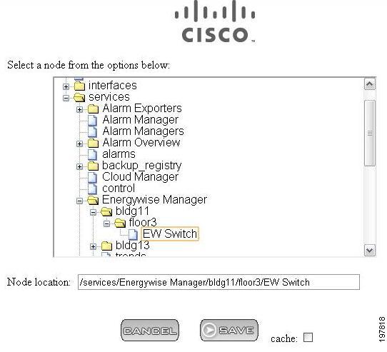
–![]() Click SAVE. A new domain has now been added and is displayed on the Configure tab.
Click SAVE. A new domain has now been added and is displayed on the Configure tab.
Step 4 ![]() (Optional) To delete the Energywise domain, click the minus (-) symbol in the Energywise Domain column. This removes the Energywise domain from the Trend Manager also.
(Optional) To delete the Energywise domain, click the minus (-) symbol in the Energywise Domain column. This removes the Energywise domain from the Trend Manager also.
The configured domains can be viewed using the following methods:
•![]() Using the Report tab
Using the Report tab
•![]() Using the Trends tab
Using the Trends tab
For viewing the configured domains using the Report tab, go to Step 5.
For viewing the configured domains using the Trends tab, see Viewing Trends
Note ![]() For domains configured using Energywise > Configure tab, you can only view them using the Trends tab. You cannot edit or delete these domains using the Trends tab.
For domains configured using Energywise > Configure tab, you can only view them using the Trends tab. You cannot edit or delete these domains using the Trends tab.
Step 5 ![]() Click the Report tab. The Report tab appears.
Click the Report tab. The Report tab appears.
This tab displays the configured domains as in the Configure tab.
Step 6 ![]() Click the ellipsis (...) button next to the Energywise Domain. Browse in the Energywise Domain column and click the domain for which you want to generate the graph.
Click the ellipsis (...) button next to the Energywise Domain. Browse in the Energywise Domain column and click the domain for which you want to generate the graph.
Note ![]() You can create only one trend for each point in a domain.
You can create only one trend for each point in a domain.
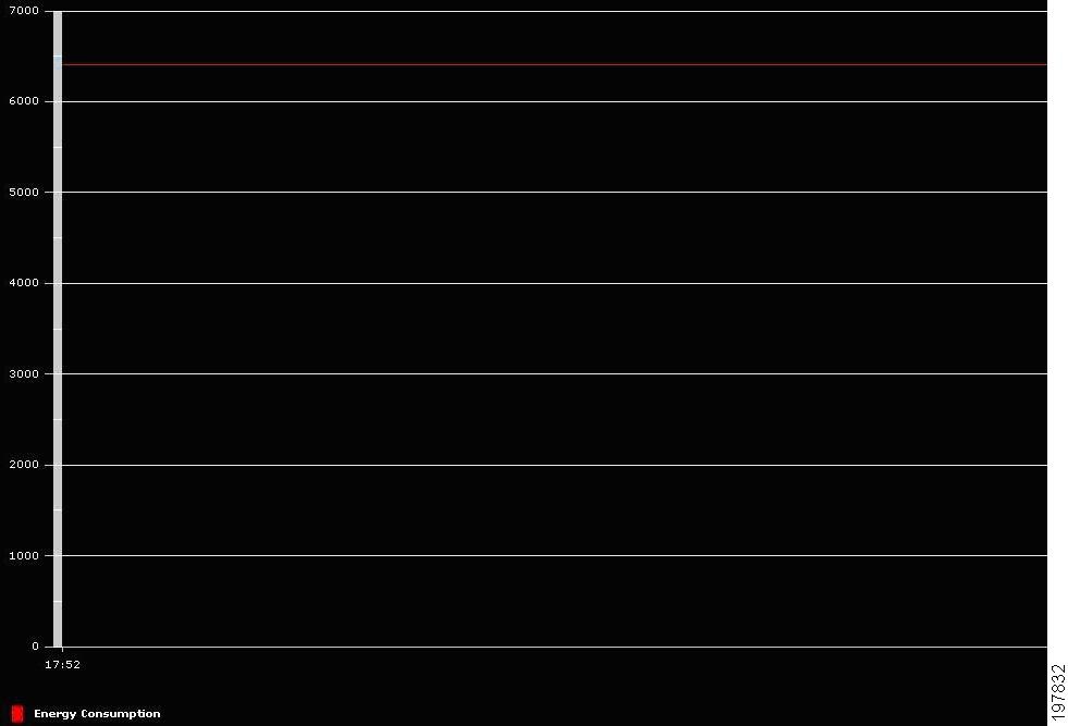
Step 7 ![]() Click GenerateGraph to generate a graph for a particular domain. A graph appears as shown in Figure 14-3.
Click GenerateGraph to generate a graph for a particular domain. A graph appears as shown in Figure 14-3.
Figure 14-3 Energywise Graph
Note ![]() Trends that are created on the Report tab can also be viewed using the Trends tab. However, you cannot use the Report tab to view trends that are created on the Trends tab.
Trends that are created on the Report tab can also be viewed using the Trends tab. However, you cannot use the Report tab to view trends that are created on the Trends tab.
Viewing a List of Entities
To view a list of entities using the Mediator web client, perform the following steps:
Step 1 ![]() Launch an Internet browser (for example, Internet Explorer) and browse to the Cisco Network Building Mediator homepage. To do so, enter the IP address of the Mediator in the Address bar of the browser and log in when prompted.
Launch an Internet browser (for example, Internet Explorer) and browse to the Cisco Network Building Mediator homepage. To do so, enter the IP address of the Mediator in the Address bar of the browser and log in when prompted.
The web client homepage appears in the Internet browser window.
Step 2 ![]() Click Nodes. The node tree pane appears.
Click Nodes. The node tree pane appears.
Step 3 ![]() In the node tree pane, expand services > Energywise Manager.
In the node tree pane, expand services > Energywise Manager.
The values for the network status and the framework status are displayed.
Step 4 ![]() Browse to the switch level to view the switch details.
Browse to the switch level to view the switch details.
 Feedback