- New and Changed Information
- Preface
- Documentation Roadmap
- Introduction
- Getting Started
- Licensing Requirements
- Using configTOOL
- Using perfectHOST
- Ports and Protocols
- KNX Deployment
- Getting Started with Mediator Web Client
- Managing Events
- Managing Security
- Managing Trends
- Managing Schedules
- Customizing HTML Pages with Web Express
- Energywise Manager
- Using Enterprise Navigation Tree
- Global Setpoints
- ADR Client
Cisco Network Building Mediator User Guide
Bias-Free Language
The documentation set for this product strives to use bias-free language. For the purposes of this documentation set, bias-free is defined as language that does not imply discrimination based on age, disability, gender, racial identity, ethnic identity, sexual orientation, socioeconomic status, and intersectionality. Exceptions may be present in the documentation due to language that is hardcoded in the user interfaces of the product software, language used based on RFP documentation, or language that is used by a referenced third-party product. Learn more about how Cisco is using Inclusive Language.
- Updated:
- April 1, 2012
Chapter: Using configTOOL
- Overview
- Installing configTOOL
- Starting configTOOL
- configTOOL Interface
- Customizing the configTOOL Interface
- Accessing Mediators Using configTOOL
- Configuring Virtual Nodes
- Calculated Virtual Point Node
- Configuring the Time Node
Mediator configTOOL
This chapter describes how to start, configure and use the Cisco Network Building Mediator configTOOL (configTOOL), and includes the following topics:
•![]() Installing configTOOL, page 4-2
Installing configTOOL, page 4-2
•![]() Starting configTOOL, page 4-3
Starting configTOOL, page 4-3
•![]() configTOOL Interface, page 4-3
configTOOL Interface, page 4-3
•![]() Customizing the configTOOL Interface, page 4-11
Customizing the configTOOL Interface, page 4-11
•![]() Accessing Mediators Using configTOOL, page 4-11
Accessing Mediators Using configTOOL, page 4-11
•![]() Configuring Virtual Nodes, page 4-13
Configuring Virtual Nodes, page 4-13
•![]() Calculated Virtual Point Node, page 4-14
Calculated Virtual Point Node, page 4-14
•![]() Configuring the Time Node, page 4-17
Configuring the Time Node, page 4-17
•![]() Configuring Logs and Exporters, page 4-22
Configuring Logs and Exporters, page 4-22
•![]() Exiting the configTOOL, page 4-42
Exiting the configTOOL, page 4-42
•![]() Uninstalling the configTOOL, page 4-43
Uninstalling the configTOOL, page 4-43
Overview
The configTOOL software is used to configure the system settings, protocols, and services on the Mediator.
The configTOOL includes the following features:
•![]() Aliases—Are used to assign alternative names to other nodes within the network.
Aliases—Are used to assign alternative names to other nodes within the network.
•![]() Interfaces—Represent the physical interfaces on the Mediator that connected to devices.
Interfaces—Represent the physical interfaces on the Mediator that connected to devices.
•![]() Services—Utilities on the Mediator such as alarms, controls, logger, network, status, and time.
Services—Utilities on the Mediator such as alarms, controls, logger, network, status, and time.
Installing configTOOL
This section includes the following topics:
•![]() Installation Instructions, page 4-2
Installation Instructions, page 4-2
Prerequisites
It is necessary that you install the Mediator configTOOL on your workstation.
For a PC running the configTOOL, we recommend that you use Windows-based platforms (95 or later) with 2 GB of RAM and 10 GB of free disk space.
Installation Instructions
To install this software, access Cisco.com at the following website:
http://www.cisco.com/en/US/products/ps10454/index.html
This software is available in the Support section at this website.

Note ![]() To download this software, you need to have a valid CCO username and password.
To download this software, you need to have a valid CCO username and password.
To download and install the software on your workstation, perform the following steps:
Step 1 ![]() Click Download Software.
Click Download Software.
Step 2 ![]() Choose Smart Connected Building Software > Cisco Network Building Mediator.
Choose Smart Connected Building Software > Cisco Network Building Mediator.
Step 3 ![]() Choose the appropriate hardware platform.
Choose the appropriate hardware platform.
Step 4 ![]() Click Network Building Mediator Configuration Software to download the configTOOL.
Click Network Building Mediator Configuration Software to download the configTOOL.
Step 5 ![]() Select the appropriate release, click the release number, and then click Download Now.
Select the appropriate release, click the release number, and then click Download Now.
Step 6 ![]() On the Download Cart window that appears, click Proceed With Download.
On the Download Cart window that appears, click Proceed With Download.
The Cisco End User Software License Agreement page appears.
Step 7 ![]() Click Agree to accept the software download rules specified in the Cisco's End User Software License Agreement page. Click Disagree to cancel the download process.
Click Agree to accept the software download rules specified in the Cisco's End User Software License Agreement page. Click Disagree to cancel the download process.
The download software page appears with two options to download the configTOOL: Download Manager Option and Non-Java Download Option.
Step 8 ![]() Click Non-Java Download Option to proceed with the download.
Click Non-Java Download Option to proceed with the download.
Note ![]() The Download Manager Option requires a working Java version of 1.4.2.xx and later. If you choose this option to download the configTOOL software, the file is saved on your PC and you are allowed to run this file to install this software.
The Download Manager Option requires a working Java version of 1.4.2.xx and later. If you choose this option to download the configTOOL software, the file is saved on your PC and you are allowed to run this file to install this software.
Step 9 ![]() Click Download URL to download the configTOOL.
Click Download URL to download the configTOOL.
The file download dialog box appears.
Step 10 ![]() Click Run.
Click Run.
You see the welcome message in the configTOOL Installer window.
Step 11 ![]() Click Next and follow the instructions to install the configTOOL. Alternatively, click Cancel to cancel the download process.
Click Next and follow the instructions to install the configTOOL. Alternatively, click Cancel to cancel the download process.
Step 12 ![]() Once you install the configTOOL, you can launch this application by choosing Start > All Programs > Cisco Systems > Cisco Systems Network Building Mediator configTOOL.
Once you install the configTOOL, you can launch this application by choosing Start > All Programs > Cisco Systems > Cisco Systems Network Building Mediator configTOOL.
Starting configTOOL
To start the configTOOL, double-click the configTOOL shortcut icon on your desktop, or choose Start > All Programs > Network Building Mediator configTOOL.
configTOOL Interface
This section describes the different elements of the configTOOL interface and includes the following topics:
•![]() About Interface Elements, page 4-3
About Interface Elements, page 4-3
•![]() Using Interface Elements, page 4-4
Using Interface Elements, page 4-4
About Interface Elements
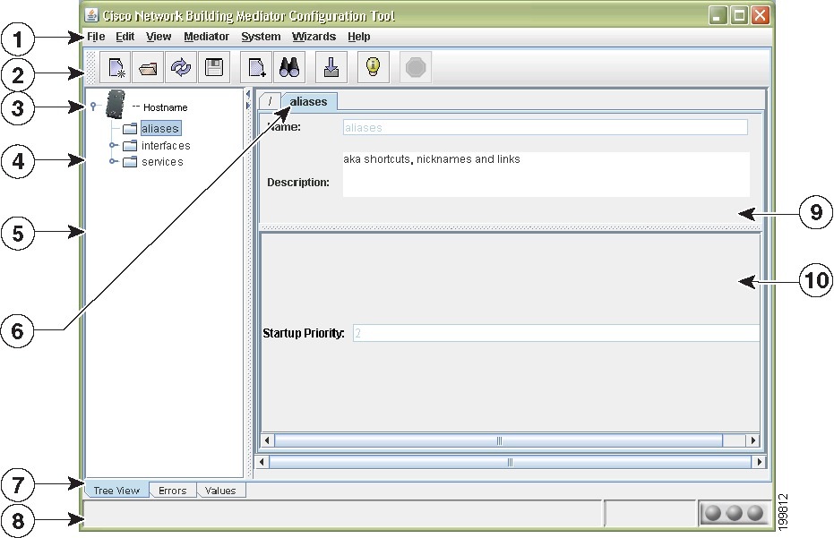
This section describes the configTOOL window with area titles, panes, and information areas (see Figure 4-1).
Figure 4-1 configTOOL Interface
Using Interface Elements
This section describes how to use the configTOOL interface and includes the following topics:
•![]() Node Tree Right-Click Menu, page 4-5
Node Tree Right-Click Menu, page 4-5
•![]() View Selection Tabs, page 4-7
View Selection Tabs, page 4-7
•![]() Mediator Units Window, page 4-8
Mediator Units Window, page 4-8
•![]() Specifying the Node Path, page 4-10
Specifying the Node Path, page 4-10
Node Tree Right-Click Menu
When you right-click a node in the node tree pane, the node tree right-click menu appears.
Table 4-1 describes the node tree right-click menu options and the associated tasks.
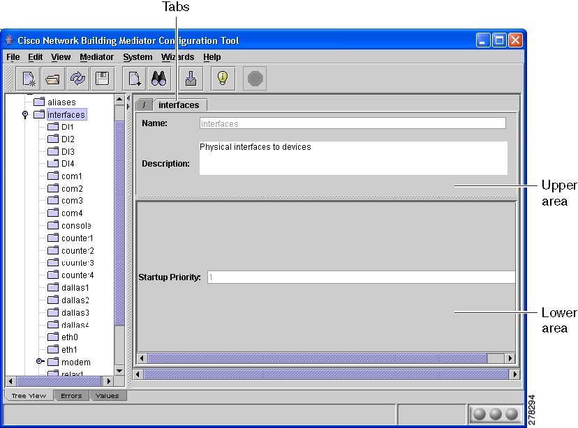
configTOOL Tabs
The configTOOL tab (see Figure 4-2) contains the data entry text boxes, in which you enter and edit node configuration parameters. The data entry text boxes are typical Windows application controls. A text box labelled in red indicates that the text box entry is mandatory.
The tab is divided into two parts, the upper area and the lower area.
•![]() The upper area contains the data entry text boxes for name and description of the selected node.
The upper area contains the data entry text boxes for name and description of the selected node.
For some nodes, the Name text box is disabled indicating that you cannot change it.
•![]() The lower area contains the data entry text box appropriate for the selected node that you are configuring.
The lower area contains the data entry text box appropriate for the selected node that you are configuring.
For some nodes, the data entry text boxes have a default entry that you can change; and for some, the data entry text boxes are disabled indicating that you cannot change it. For some nodes, the pane does not have any data entry text boxes.
In some cases, a wizard guides you through the node configuration procedure.
Some text boxes prompt you to enter the node path. The text box may be in the form of a data entry text box, where you use the Copy Node Path command to insert the entry.
To complete the tab text boxes, perform the following steps:
Step 1 ![]() In the node tree pane, expand or collapse the node tree to list the interface nodes.
In the node tree pane, expand or collapse the node tree to list the interface nodes.
Step 2 ![]() Click the node you want to configure.
Click the node you want to configure.
The tab appears in the right pane of the window. The default name and description of the connected device appear in the upper area (see Figure 4-2).
Figure 4-2 Mediator configuration Tool Window
Note ![]() The tab appears automatically if the Synchronize Forms option under View > Options is selected. If the Options check box is selected, use the Edit function to display the form.
The tab appears automatically if the Synchronize Forms option under View > Options is selected. If the Options check box is selected, use the Edit function to display the form.
You can enter a new name and description to identify the selected node. When you rename a node, the updated name replaces the default name in the node tree.
Note ![]() The screen tooltip appears when you position the cursor over the node in the node tree. In this example, you cannot change the default name.
The screen tooltip appears when you position the cursor over the node in the node tree. In this example, you cannot change the default name.
Step 3 ![]() Right-click the node you want to configure, and then choose Add (see Node Tree Right-Click Menu, page 4-5).
Right-click the node you want to configure, and then choose Add (see Node Tree Right-Click Menu, page 4-5).
Step 4 ![]() From the Available Devices dialog box that appears, choose periodic value driver (driver), and click OK.
From the Available Devices dialog box that appears, choose periodic value driver (driver), and click OK.
A new child node appears under the selected node in the node tree.
The data entry text boxes of the newly added child node appear on the driver tab within the tab. The default name and description text box of the node appear in the upper area of the driver tab; and other mandatory and optional entry text boxes appear in the lower area.
Step 5 ![]() In the Name text box, enter the new name.
In the Name text box, enter the new name.
Step 6 ![]() In the Description text box, enter the new description.
In the Description text box, enter the new description.
Note ![]() The description entered in this text box appears in the tooltip, which appears when you position the cursor over or near the node in the node tree.
The description entered in this text box appears in the tooltip, which appears when you position the cursor over or near the node in the node tree.
Step 7 ![]() In the lower area of the driver tab, enter the appropriate parameters in the data entry text boxes.
In the lower area of the driver tab, enter the appropriate parameters in the data entry text boxes.
View Selection Tabs
The view selection tabs, located at the bottom of the configTOOL window, allow you to view all the options that contain different information on the node tree pane and the data entry pane. This section describes each of these tabs and includes the following topics:
•![]() Accessing the Node Tree, page 4-7
Accessing the Node Tree, page 4-7
•![]() Accessing the Errors View, page 4-7
Accessing the Errors View, page 4-7
•![]() Accessing the Values View, page 4-7
Accessing the Values View, page 4-7
Accessing the Node Tree
The node tree is the default view of the configTOOL window. You can click the Tree View tab to return to this view from another view.
Accessing the Errors View
When you click the Errors tab, the configTOOL window displays the Errors view. The Errors view displays a list of error messages the Mediator has generated during the current session. The Errors view is a diagnostic tool intended to assist developers and technicians.
Accessing the Values View
When you click the Values tab, the configTOOL window displays the Values view. The Values view displays the list of values of the nodes currently configured for logging.
Status Bar
The Status bar is located at the bottom of the configTOOL window (see Figure 4-3). The Mediator uses this area to display messages and graphics that indicate the status of activity in the currently selected Mediator.
The Status bar contains three areas:
•![]() The Status Message area is located on the left. Here the configTOOL displays messages that tell you about operations in progress. For example, when you open an existing Mediator, it displays the message Opening configuration.
The Status Message area is located on the left. Here the configTOOL displays messages that tell you about operations in progress. For example, when you open an existing Mediator, it displays the message Opening configuration.
•![]() The Progress Indicator area is located in the middle. A blue rectangle sweeps back and forth in the area while an operation is in progress.
The Progress Indicator area is located in the middle. A blue rectangle sweeps back and forth in the area while an operation is in progress.
•![]() The Online/Offline indicator is located on the right. When the Mediator is online, the indicator is green; and when it is offline, the indicator is red.
The Online/Offline indicator is located on the right. When the Mediator is online, the indicator is green; and when it is offline, the indicator is red.
Figure 4-3 Status Bar

Mediator Units Window
The Mediator Units window is a frequently used feature of the configTOOL. It appears when you initiate either of the following two operations:
•![]() When you open the configuration file of a Mediator in a network while running the configTOOL.
When you open the configuration file of a Mediator in a network while running the configTOOL.
You can perform this task by choosing File > Open Mediator > From Network.
Note ![]() When opened this way, the window title bar displays the label Open Mediator Configuration.
When opened this way, the window title bar displays the label Open Mediator Configuration.
•![]() When you save the configuration file and restart the Mediator.
When you save the configuration file and restart the Mediator.
You can perform this task by choosing File > Save As.
Note ![]() When opened this way, the window title bar displays the label Save Mediator Configuration.
When opened this way, the window title bar displays the label Save Mediator Configuration.
The sections describe the controls included in the Mediator Units window. These include the toolbar located in the upper right-hand corner of the window, and a right-click menu. In addition, the Restart Mediator drop-down list appears in the lower left corner of the window when you choose File > Save As.
This section includes the following topics:
•![]() Mediator Units Window Toolbar, page 4-8
Mediator Units Window Toolbar, page 4-8
•![]() Mediator Units Window Right-Click Menu, page 4-9
Mediator Units Window Right-Click Menu, page 4-9
•![]() Using the Mediator Units Window to Restart the Mediator, page 4-10
Using the Mediator Units Window to Restart the Mediator, page 4-10
Mediator Units Window Toolbar
The Mediator Units window toolbar contains six tools representing tools that perform configuration file management functions. However, at any given point in time, the toolbar displays only five tools.
•![]() When the window title bar contains the label Open Mediator Configuration, the first tool allows you to open files.
When the window title bar contains the label Open Mediator Configuration, the first tool allows you to open files.
•![]() When the window title bar contains the label Save Mediator Configuration, the first tool allows you to save files.
When the window title bar contains the label Save Mediator Configuration, the first tool allows you to save files.
Table 4-2 describes these tools and its associated tasks.
Mediator Units Window Right-Click Menu
You can right-click the row describing a Mediator to view the right-click menu commands. Table 4-3 describes the right-click menu commands.
Using the Mediator Units Window to Restart the Mediator
To use the Mediator Units window to restart the Mediator, perform the following steps:
Note ![]() When you make changes to the configuration file of the active Mediator, you must restart the Mediator for the changes to take effect.
When you make changes to the configuration file of the active Mediator, you must restart the Mediator for the changes to take effect.
Step 1 ![]() Choose File > Save As.
Choose File > Save As.
The Save Mediator Configuration dialog box appears. The active Mediator host is selected.
Step 2 ![]() From the Restart Mediator drop-down list, choose soft or hard.
From the Restart Mediator drop-down list, choose soft or hard.
The soft option performs a soft reboot (a soft reboot restarts the panework only), and the hard option performs a hard reboot (a hard reboot restarts both the Mediator Framework and the MOE).
Specifying the Node Path
The following sections describe how to specify the path of a node. Some node entries use the value of another node in determining their own values. The data entry pane of these nodes displays the text box in which you to enter the path to that other node. The configTOOL provides two methods for specifying the node path. This section includes the following topics:
•![]() Using the Node Selector, page 4-10
Using the Node Selector, page 4-10
•![]() Using the Copy Node Path Command, page 4-10
Using the Copy Node Path Command, page 4-10
Using the Node Selector
To specify the node path using the Node Selector, perform the following steps:
Step 1 ![]() In the configTOOL window, click the driver node under the Interfaces/relay1 node.
In the configTOOL window, click the driver node under the Interfaces/relay1 node.
The driver tab displays the data entry text boxes.
Step 2 ![]() In the lower area of the tab, click the arrow next to the Input Node text box.
In the lower area of the tab, click the arrow next to the Input Node text box.
Step 3 ![]() From the Node Selector dialog box, choose the DI1 node under the interfaces node.
From the Node Selector dialog box, choose the DI1 node under the interfaces node.
The node path /interfaces/DI1 is the value of Digital Input 01.
Step 4 ![]() Click Select.
Click Select.
The node path of the DI1 node appears in the Input Node text box.
Using the Copy Node Path Command
To use the Copy Node Path command, perform the following steps:
Step 1 ![]() In the configTOOL window, click the DI1 node under the interfaces node.
In the configTOOL window, click the DI1 node under the interfaces node.
Step 2 ![]() Right-click the DI1 node, and choose Copy Node Path.
Right-click the DI1 node, and choose Copy Node Path.
Step 3 ![]() Click the node to which you want to copy the path.
Click the node to which you want to copy the path.
Step 4 ![]() Press Ctrl-C.
Press Ctrl-C.
The file path of the selected node is copied to the data entry text box.
Using the Tooltips and Keyboard Shortcuts
The configTOOL displays a tooltip when you position the cursor over any of the areas in the configTOOL window.
Customizing the configTOOL Interface
You can set a user preference to control the view of the configTOOL interface that appears when you initially log in.
To set a view, in the configTOOL window, choose View > Look and Feel, and choose the appropriate view.
Accessing Mediators Using configTOOL
This section describes the procedure to connect to your Mediator and includes the following topics"
•![]() Connecting to a Local Mediator, page 4-11
Connecting to a Local Mediator, page 4-11
•![]() Connecting to a Remote Mediator, page 4-12
Connecting to a Remote Mediator, page 4-12
•![]() Restarting and Rebooting the Mediator, page 4-12
Restarting and Rebooting the Mediator, page 4-12
Connecting to a Local Mediator
To connect to the Mediator using the configTOOL, perform the following steps:
Step 1 ![]() Start the configTOOL and choose File > Open Mediator > From Network.
Start the configTOOL and choose File > Open Mediator > From Network.
The Open Mediator Configuration dialog box appears.
Step 2 ![]() Select the row describing the Mediator host you want to configure and click OK.
Select the row describing the Mediator host you want to configure and click OK.
The Login to Mediator dialog box appears.
Step 3 ![]() (Optional) If your Mediator is not listed in the Mediator Units list, click Add Favorite Mediator.
(Optional) If your Mediator is not listed in the Mediator Units list, click Add Favorite Mediator.
The Enter Host Name dialog box appears.
Step 4 ![]() (Optional) In the Mediator Host name text box, enter the IP address or hostname of your Mediator, and then click OK to continue with Step 3.
(Optional) In the Mediator Host name text box, enter the IP address or hostname of your Mediator, and then click OK to continue with Step 3.
Step 5 ![]() In the Login to Mediator dialog box, enter the username and the password, and then click OK.
In the Login to Mediator dialog box, enter the username and the password, and then click OK.
The configTOOL window displays the node tree of the selected Mediator.
You can also connect to a Mediator from options such as:
•![]() From File—Opens a Mediator from an existing file.
From File—Opens a Mediator from an existing file.
•![]() From Recently Opened—Opens a Mediator from the list of recently opened Mediator.
From Recently Opened—Opens a Mediator from the list of recently opened Mediator.
•![]() From Favorite—Opens a Mediator from those stored under the favorite locations.
From Favorite—Opens a Mediator from those stored under the favorite locations.
Connecting to a Remote Mediator
Note ![]() The Mediator menu SSH Terminal command allows you to log in to your local Mediator. The System menu SSH Terminal command allows you to log in to a remote Mediator.
The Mediator menu SSH Terminal command allows you to log in to your local Mediator. The System menu SSH Terminal command allows you to log in to a remote Mediator.
To log in to a remote Mediator, perform the following steps:
Step 1 ![]() Start the configTOOL (see Starting configTOOL, page 4-3).
Start the configTOOL (see Starting configTOOL, page 4-3).
The configTOOL window appears.
Step 2 ![]() Choose System > SSH Terminal.
Choose System > SSH Terminal.
The Enter Host Name dialog box appears.
Step 3 ![]() In the Host name text box, enter the IP address of the remote Mediator.
In the Host name text box, enter the IP address of the remote Mediator.
Step 4 ![]() Click OK.
Click OK.
The SSH User Authentication dialog box appears.
Step 5 ![]() In the Username text box, enter the username.
In the Username text box, enter the username.
Step 6 ![]() In the Password text box, enter the Password.
In the Password text box, enter the Password.
Step 7 ![]() Click Login.
Click Login.
The Secure Terminal window appears.
Restarting and Rebooting the Mediator
Restarting (also called a soft reboot) restarts only the framework. Rebooting (also called a hard reboot) restarts both the framework and the Mediator Operating Environment (MOE).
Note ![]() When you modify the configuration file on the active mediator and save the files, the Mediator restarts automatically to show the modified configuration. When you modify an offline configuration file, you have to restart the Mediator manually.
When you modify the configuration file on the active mediator and save the files, the Mediator restarts automatically to show the modified configuration. When you modify an offline configuration file, you have to restart the Mediator manually.
You can restart the Mediator when you need to save the changes to the existing configurations. You can reboot the Mediator, when you upgrade the MOE or power on the Mediator.
•![]() To restart the Mediator (framework only), choose Open the Mediator > Restart.
To restart the Mediator (framework only), choose Open the Mediator > Restart.
•![]() To reboot the Mediator (framework and MOE), choose Open the Mediator > Reboot.
To reboot the Mediator (framework and MOE), choose Open the Mediator > Reboot.
The Online/Offline Indicator turns red (see Status Bar, page 4-7) and the Power LED stops flashing.
When the Mediator finishes restarting or rebooting, the Online/Offline Indicator turns green and the Power LED begins emitting three long flashes followed by a pause (Morse code O). This indicates that the panework functions are normal.
The Mediator Units window also has controls for restarting or rebooting the Mediator (See Mediator Units Window, page 4-8).
Configuring Virtual Nodes
This section describes a virtual node and includes the following topics:
•![]() About Virtual Node, page 4-13
About Virtual Node, page 4-13
•![]() Adding a Virtual Node, page 4-13
Adding a Virtual Node, page 4-13
About Virtual Node
The Mediator configTOOL supports ten virtual nodes. These are child nodes that can be configured under many types of interface and service parent nodes. Unlike the interface nodes, which represent a physical device or data point, virtual nodes represent a functionality. For example, mathematical calculation. A virtual node may introduce a new value into the system, change the value of its parent node, or use the value of its parent node to produce a different value.
The value of the virtual node is available to all other nodes including the parent node in the system. For example, the value of a Multiplier node that is configured as the child node of a Digital Input parent node may also be used by an unrelated counter node.
Adding a Virtual Node
To add a virtual node, perform the following steps:
Step 1 ![]() Start the configTOOL and connect to the Mediator.
Start the configTOOL and connect to the Mediator.
For more information, see the following sections:
•![]() Starting configTOOL, page 4-3.
Starting configTOOL, page 4-3.
•![]() Accessing Mediators Using configTOOL, page 4-11.
Accessing Mediators Using configTOOL, page 4-11.
Step 2 ![]() Click interfaces to display the available interfaces.
Click interfaces to display the available interfaces.
Step 3 ![]() To configure a virtual node under a parent node, click the parent node. For example, click DI1 (Digital Input1).
To configure a virtual node under a parent node, click the parent node. For example, click DI1 (Digital Input1).
Step 4 ![]() Right-click the DI1 node, and then choose Add from the right-click menu.
Right-click the DI1 node, and then choose Add from the right-click menu.
The Available Devices dialog box appears listing the different types of virtual nodes.
Step 5 ![]() In the Available Devices dialog box, choose Calculated Virtual Point (calculator), and then click OK.
In the Available Devices dialog box, choose Calculated Virtual Point (calculator), and then click OK.
A new child node (calculator node) appears under the parent node DI1 in the node tree pane.
The calculator tab displays the default name, description, and the configurable parameters of the node. You can change the default name and description of the calculator node (or retain the defaults). The configurable parameters are located in the lower area of the data entry window. To modify the parameters, choose an appropriate value from the relevant drop-down list or enter a value in the text boxes provided.
Note ![]() All text boxes that are labelled in red indicate that the text box entry is mandatory.
All text boxes that are labelled in red indicate that the text box entry is mandatory.
Step 6 ![]() In the Statement text box, enter the expression that you want the node to calculate. For example, (a+b)/2 (the average of the values of the two temperature sensor nodes).
In the Statement text box, enter the expression that you want the node to calculate. For example, (a+b)/2 (the average of the values of the two temperature sensor nodes).
a = the value of the F (degrees Fahrenheit) child node of Control_Room_Temp_01.
b = the value of the F (degrees Fahrenheit) child node of Control_Room_Temp_02.
Step 7 ![]() Click + to define the variables.
Click + to define the variables.
Step 8 ![]() In the Variable text box, do the following:
In the Variable text box, do the following:
•![]() Enter the variable name in the Variable Name column. For example, a.
Enter the variable name in the Variable Name column. For example, a.
•![]() Enter the node references path in the Node Reference column. For example, /interfaces/dallas1/Control_Room_Temp_01/F. The value that you enter in the Node Reference column will determine the value of the parent node.
Enter the node references path in the Node Reference column. For example, /interfaces/dallas1/Control_Room_Temp_01/F. The value that you enter in the Node Reference column will determine the value of the parent node.
Step 9 ![]() Repeat Step 8 to define the variable b.
Repeat Step 8 to define the variable b.
Step 10 ![]() Save the configuration.
Save the configuration.
Calculated Virtual Point Node
This section describes the functionality and configuration of a calculated virtual point node, also known as the calculator node, and includes the following topics:
•![]() About Calculated Virtual Point, page 4-14
About Calculated Virtual Point, page 4-14
•![]() Configuring the Calculator Node, page 4-16
Configuring the Calculator Node, page 4-16
About Calculated Virtual Point
A calculated virtual point (calculator) node allows you to use the mathematical functionality built into the Mediator software, the values of other nodes, and the constants to configure an expression that determines the value of the node. That value becomes available to other nodes in the Mediator environment. The calculator node supports six, basic arithmetic operations as described in Table 4-4.
The calculator follows the normal mathematical order of operations:
•![]() Parentheses ()
Parentheses ()
•![]() Exponents **
Exponents **
•![]() Multiplication *, division \, and remainder %
Multiplication *, division \, and remainder %
•![]() Addition + and subtraction -
Addition + and subtraction -
The calculator supports the mathematical functions as described in Table 4-5.
The Calculator also supports the following two mathematical constants:
•![]() pi—The mathematical constant pi.
pi—The mathematical constant pi.
•![]() e—The mathematical constant e.
e—The mathematical constant e.
The Calculator supports the logical operators as described in Table 4-6.
Configuring the Calculator Node
The following procedure uses a simple example to explain how you can configure a calculator node. The value of the node is the average of the values of two temperature sensors, the F (degrees Fahrenheit) child node of Control_Room_Temp_01 and the F (degrees Fahrenheit) child node of Control_Room_Temp_02.
To configure the calculator node, perform the following steps:
Step 1 ![]() Perform Step 1 and Step 2 of the "Adding a Virtual Node" section on page 4-13.
Perform Step 1 and Step 2 of the "Adding a Virtual Node" section on page 4-13.
Step 2 ![]() In the node tree pane, expand the node tree, click interfaces, and then click Dallas1.
In the node tree pane, expand the node tree, click interfaces, and then click Dallas1.
Step 3 ![]() Right-click the Dallas1 node, and then choose Add from the right-click menu.
Right-click the Dallas1 node, and then choose Add from the right-click menu.
The Available Devices dialog box appears.
Step 4 ![]() In the Available devices dialog box, choose Calculated Virtual Point (calculator), and then click OK.
In the Available devices dialog box, choose Calculated Virtual Point (calculator), and then click OK.
A new child node (calculator node) appears under the parent node (Dallas1) node in the node tree pane.
The calculator tab displays the default name, description, and the configurable parameters of the calculator node.
Step 5 ![]() (Optional) To change the default name of the child node, in the Name text box, enter the new name for the modem, and then press Enter.
(Optional) To change the default name of the child node, in the Name text box, enter the new name for the modem, and then press Enter.
Step 6 ![]() (Optional) In the Description text box, enter a description to identify the purpose of the calculator child node.
(Optional) In the Description text box, enter a description to identify the purpose of the calculator child node.
Step 7 ![]() In the Statement text box, enter the expression that you want the node to calculate. For example, (a+b)/2 (the average of the values of the two temperature sensor nodes).
In the Statement text box, enter the expression that you want the node to calculate. For example, (a+b)/2 (the average of the values of the two temperature sensor nodes).
a = the value of the F (degrees Fahrenheit) child node of Control_Room_Temp_01.
b = the value of the F (degrees Fahrenheit) child node of Control_Room_Temp_02.
Step 8 ![]() Click + to define the variables.
Click + to define the variables.
Step 9 ![]() In the Variable text box, do the following:
In the Variable text box, do the following:
•![]() Enter the variable name in the Variable Name column. For example, a.
Enter the variable name in the Variable Name column. For example, a.
•![]() Enter the node reference path /interfaces/dallas1/Control_Room_Temp_01/F in the Node Reference column. The value that you enter in the Node Reference column will determine the value of the parent node.
Enter the node reference path /interfaces/dallas1/Control_Room_Temp_01/F in the Node Reference column. The value that you enter in the Node Reference column will determine the value of the parent node.
Step 10 ![]() Repeat Step 9 to define the variable b.
Repeat Step 9 to define the variable b.
Step 11 ![]() Save the configuration.
Save the configuration.
Configuring the Time Node
This section describes the different time nodes, explains how to configure the time nodes in the Mediator and includes the following topics:
•![]() Configuring Date and Time Manually, page 4-18
Configuring Date and Time Manually, page 4-18
•![]() Formatting the Date and Time Using a Calculated Virtual Point, page 4-18
Formatting the Date and Time Using a Calculated Virtual Point, page 4-18
•![]() Configuring a Time Server, page 4-19
Configuring a Time Server, page 4-19
About Time Node
The time node implements the date and time service in the Mediator. The time node allows you to specify two types of date and time settings in the Mediator.
1. ![]() Set the date and time in the Mediator manually.
Set the date and time in the Mediator manually.
2. ![]() Update the date and time settings in the time server automatically.
Update the date and time settings in the time server automatically.
The time node output is a value that expresses the time as the number of seconds since January 1, 1970 (the standard UNIX method of reporting time). The time node has several pre-configured child nodes. Similar to the time node, the outputs of the UTC (Coordinated Universal Time, also called Greenwich Mean Time) node and the local node are also in number of seconds since January 1, 1970. The UTC and the local nodes both have eight pre-configured child nodes, that provides the output values for the current day, hour, and so on.
Note ![]() The value of the weekday node is a number in the range of 0 to 6, where 0 = Monday, 1 = Tuesday, 2 = Wednesday, and so on. The synch_continuous and synch_periodic nodes allow you to configure a time server.
The value of the weekday node is a number in the range of 0 to 6, where 0 = Monday, 1 = Tuesday, 2 = Wednesday, and so on. The synch_continuous and synch_periodic nodes allow you to configure a time server.
Configuring Date and Time Manually
To configure the date and time manually, perform the following steps:
Step 1 ![]() Perform Step 1 and Step 2 of the "Adding a Virtual Node" section on page 4-13.
Perform Step 1 and Step 2 of the "Adding a Virtual Node" section on page 4-13.
Step 2 ![]() In the node tree pane, expand the node tree, click services, and then click time.
In the node tree pane, expand the node tree, click services, and then click time.
The time tab for the time node displays the default name, description, and the configurable parameters.
Note ![]() You cannot change the default name.
You cannot change the default name.
Step 3 ![]() (Optional) To change the description of the time node, in the Description text box, enter a description to identify the purpose of this node.
(Optional) To change the description of the time node, in the Description text box, enter a description to identify the purpose of this node.
Step 4 ![]() In the Date and Time text box, enter the current date and time in your location, in the following format: dd-mmm-yyyy hh:mm:ss. For example, 07-Jul-2011 08.33.16.
In the Date and Time text box, enter the current date and time in your location, in the following format: dd-mmm-yyyy hh:mm:ss. For example, 07-Jul-2011 08.33.16.
Step 5 ![]() From the Time Zone drop-down list, choose the time zone of your location. For example, PST.
From the Time Zone drop-down list, choose the time zone of your location. For example, PST.
Step 6 ![]() Click Set Date/Time.
Click Set Date/Time.
The date/time was set dialog box appears.
Step 7 ![]() Click OK.
Click OK.
Note ![]() The UTC, local child nodes, and their inherent child nodes do not require any specific configuration.
The UTC, local child nodes, and their inherent child nodes do not require any specific configuration.
Formatting the Date and Time Using a Calculated Virtual Point
To format the date and time, and to display a timestamp, perform the following steps:
Step 1 ![]() Perform Step 1 and Step 2 of the "Adding a Virtual Node" section on page 4-13.
Perform Step 1 and Step 2 of the "Adding a Virtual Node" section on page 4-13.
Step 2 ![]() In the node tree pane, expand the node tree, and then choose interfaces > virtuals.
In the node tree pane, expand the node tree, and then choose interfaces > virtuals.
Step 3 ![]() Right-click the virtuals node, and choose Add from the right-click menu.
Right-click the virtuals node, and choose Add from the right-click menu.
The Available Devices dialog box appears.
Step 4 ![]() In the Available Devices dialog box, choose Calculated Virtual Point (calculator), and then click OK.
In the Available Devices dialog box, choose Calculated Virtual Point (calculator), and then click OK.
Step 5 ![]() Click + to define the variables.
Click + to define the variables.
Step 6 ![]() In the Variable text box, do the following:
In the Variable text box, do the following:
•![]() Enter the variable name in the Variable Name column. For example, h.
Enter the variable name in the Variable Name column. For example, h.
•![]() Enter the node reference path in the in the Node Reference column. For example, /services/time/local/hour.
Enter the node reference path in the in the Node Reference column. For example, /services/time/local/hour.
Step 7 ![]() Repeat Step 5 and Step 6 to create two other variables with the variable names, m and s, with the node references path /services/time/local/minute and /services/time/local/hour respectively.
Repeat Step 5 and Step 6 to create two other variables with the variable names, m and s, with the node references path /services/time/local/minute and /services/time/local/hour respectively.
Step 8 ![]() In the Statement text box enter the expression string '%d:%d:%d' % (h, m, s).
In the Statement text box enter the expression string '%d:%d:%d' % (h, m, s).
The value of the node gets time formatted as hh:mm:ss.
Step 9 ![]() Save the configuration.
Save the configuration.
Configuring a Time Server
This section describes how to configure the time server and includes the following topics:
•![]() Configuring a Continuously Available Time Server, page 4-19
Configuring a Continuously Available Time Server, page 4-19
•![]() Configuring an Intermittently Available Time Server, page 4-20
Configuring an Intermittently Available Time Server, page 4-20
You can configure the date and time in the Mediator by using a time server. The time node has two child nodes that you can use to configure the Mediator to use a time server:
•![]() The synch_continuous node allows you to configure a time server continuously.
The synch_continuous node allows you to configure a time server continuously.
•![]() The synch_periodic node allows you to configure a time server at periodic intervals.
The synch_periodic node allows you to configure a time server at periodic intervals.
Configuring a Continuously Available Time Server
To configure the available time server, perform the following steps:
Step 1 ![]() In the node tree pane, expand the node tree, then choose services > time > sync_continuous.
In the node tree pane, expand the node tree, then choose services > time > sync_continuous.
The sync_continuous tab displays the default name, description and the configurable parameters of the sync_continuous node.
Note ![]() You cannot change the default name of the sync-continuous node.
You cannot change the default name of the sync-continuous node.
Step 2 ![]() (Optional) In the Description text box, enter a description to identify the purpose of the synch_continuous child node or retain the default description.
(Optional) In the Description text box, enter a description to identify the purpose of the synch_continuous child node or retain the default description.
Step 3 ![]() Select the Enabled check box to enable the node. By default, the node is enabled.
Select the Enabled check box to enable the node. By default, the node is enabled.
Step 4 ![]() In the connection drop-down list, retain the default value, which is LAN.
In the connection drop-down list, retain the default value, which is LAN.
Step 5 ![]() Click + to specify one or more time servers.
Click + to specify one or more time servers.
Step 6 ![]() In the Time Servers:Server entry text box, enter the hostname or the IP address of the time server.
In the Time Servers:Server entry text box, enter the hostname or the IP address of the time server.
Note ![]() Ensure that an external NTP (Network Time Protocol) is available before entering the IP address and the connection is always LAN.
Ensure that an external NTP (Network Time Protocol) is available before entering the IP address and the connection is always LAN.
This step ensures that the time in all the Mediators is synchronized to allow scheduling (For example, equipment start and stop times), and logging operations to commence at predefined times and is recommended for all large enterprise deployements.
Step 7 ![]() Repeat Step 5 and Step 6 for each additional time server that you want to configure.
Repeat Step 5 and Step 6 for each additional time server that you want to configure.
Configuring an Intermittently Available Time Server
To configure an intermittently available time server, perform the following steps:
Step 1 ![]() In the node tree pane, expand the node tree, then choose services > periodic.
In the node tree pane, expand the node tree, then choose services > periodic.
The sync_periodic tab displays the default name, description, and the configurable parameters of the sync_periodic node.
Note ![]() You cannot change the default name of the sync-continuous node.
You cannot change the default name of the sync-continuous node.
Step 2 ![]() (Optional) In the Description text box, enter a description to identify the purpose of the sync_periodic child node (or leave the defaults).
(Optional) In the Description text box, enter a description to identify the purpose of the sync_periodic child node (or leave the defaults).
Step 3 ![]() Select the Enabled check box.
Select the Enabled check box.
Step 4 ![]() In the Connection type drop-down list, retain the default value, which is LAN.
In the Connection type drop-down list, retain the default value, which is LAN.
Note ![]() The Dial out option is not supported.
The Dial out option is not supported.
Step 5 ![]() You can specify the interval at which you want the Mediator to connect to the time server. The configurable parameters are located in the lower area of the data entry pane. To do so, enter a appropriate value in the text boxes provided.
You can specify the interval at which you want the Mediator to connect to the time server. The configurable parameters are located in the lower area of the data entry pane. To do so, enter a appropriate value in the text boxes provided.
•![]() In the Minutes text box, enter the time interval in minutes to connect to the time server more than once in an hour.
In the Minutes text box, enter the time interval in minutes to connect to the time server more than once in an hour.
•![]() In the Hours text box, enter the time interval in minutes to connect to the time server less than once an hour but more than once a day.
In the Hours text box, enter the time interval in minutes to connect to the time server less than once an hour but more than once a day.
•![]() In the Days text box, enter the interval in minutes to connect to the time server less than once a day.
In the Days text box, enter the interval in minutes to connect to the time server less than once a day.
Step 6 ![]() Click + to specify one or more time server.
Click + to specify one or more time server.
Step 7 ![]() In the Time Servers:Server entry text box, enter the hostname or the IP address of the time server.
In the Time Servers:Server entry text box, enter the hostname or the IP address of the time server.
Step 8 ![]() Repeat Step 6 and Step 7 for each additional time server that you want to configure.
Repeat Step 6 and Step 7 for each additional time server that you want to configure.
Viewing Nodes
You can view the online values of the nodes configured on the Mediator. The Mediator web client allows you to navigate to a node and then view the node details.
To view the details associated with a node, perform the following steps:
Step 1 ![]() In the Mediator web client homepage, click Nodes.
In the Mediator web client homepage, click Nodes.
The Nodes pane appears.
Step 2 ![]() Click one of the children nodes. Navigate to the node you want to view.
Click one of the children nodes. Navigate to the node you want to view.
Step 3 ![]() Click the node. The corresponding details are displayed in the pane.
Click the node. The corresponding details are displayed in the pane.
Using Snippets
Snippets are a set of configuration files which can be reused because doing so allows you to minimize repetitive configuration. You can use the configTOOL to create snippets, save the configured files on your computer hard disk, and import these files when required.
This section describes how to create and import snippets and includes the following topics:
•![]() Creating a Snippet, page 4-21
Creating a Snippet, page 4-21
•![]() Importing a Snippet, page 4-21
Importing a Snippet, page 4-21
Creating a Snippet
To create a snippet, perform the following steps:
Step 1 ![]() In the configTOOL window, expand the aliases node to display the sub nodes.
In the configTOOL window, expand the aliases node to display the sub nodes.
Step 2 ![]() Right-click the RTU1 node and choose Output From Here. The Output Mediator Configuration dialog box appears.
Right-click the RTU1 node and choose Output From Here. The Output Mediator Configuration dialog box appears.
Step 3 ![]() In the Output Mediator Configuration dialog box, click Save to File.
In the Output Mediator Configuration dialog box, click Save to File.
Step 4 ![]() Save the file in any directory on your computer hard disk. The file should be saved as an Extensible Markup Language (XML extension) file. For example: rtu1snippet.xml
Save the file in any directory on your computer hard disk. The file should be saved as an Extensible Markup Language (XML extension) file. For example: rtu1snippet.xml
Importing a Snippet
To import a snippet, perform the following steps:
Step 1 ![]() In the configTOOL window, right-click the Aliases node, and choose System>Import configuration fragment.
In the configTOOL window, right-click the Aliases node, and choose System>Import configuration fragment.
Step 2 ![]() Browse through the computer directory and locate the XML file that you want to import in the configTOOL. For example: rtu1snippet.xml
Browse through the computer directory and locate the XML file that you want to import in the configTOOL. For example: rtu1snippet.xml
Step 3 ![]() Click OK to import the selected snippet.
Click OK to import the selected snippet.
The imported snippet now appears as a node under the aliases node.
Configuring Logs and Exporters
Logs are used to periodically collect and store Mediator data in a file on the Mediator. You can analyze the efficiency, record the energy usage, and troubleshoot associated problems of the Heating, Ventilating, and Air Conditioning (HVAC) system with the help of the logs data.
The Log Wizard in the configTOOL enables you to configure the logs to define the interval at which the data can be stored. You can then export the logged data by configuring an exporter.
The process of configuring logs and exporters using the Log Wizard can be summarized as follows:
Step 1 : Create a new log. |
See Step 4 of the "Configuring Logs" section on page 4-22. |
Step 2 : Edit log columns. |
See Step 7 of the "Configuring Logs" section on page 4-22. |
Step 3 : Define log exporters. (Optional) |
|
Step 4 : Define formatters. |
|
Step 5 : Define transporters |
|
Step 6 : Save the configuration. |
- |
This section describes how to configure logs and exporters and includes the following topics:
•![]() Configuring Exporters, page 4-24
Configuring Exporters, page 4-24
Configuring Logs
To configure logs, perform the following steps:
Step 1 ![]() In the node tree pane, expand the node tree, click the service node, and then click the logger node.
In the node tree pane, expand the node tree, click the service node, and then click the logger node.
The logger tab appears.
Step 2 ![]() Click the Plug-In tab in the lower area of the logger tab.
Click the Plug-In tab in the lower area of the logger tab.
A Wizard is available button appears on the Plug-In tab.
Step 3 ![]() Click Wizard is available. The Log Wizard screen appears.
Click Wizard is available. The Log Wizard screen appears.
Step 4 ![]() Click Create New Log. The Log Wizard opens in the Edit Log Details mode.
Click Create New Log. The Log Wizard opens in the Edit Log Details mode.
Step 5 ![]() In the Edit Log Details window, perform the following steps:
In the Edit Log Details window, perform the following steps:
a. ![]() In the Log Name text box, enter a descriptive name for the new log.
In the Log Name text box, enter a descriptive name for the new log.
Note ![]() Ensure that you specify a unique name for the log because you cannot configure a log with a name that already exists.
Ensure that you specify a unique name for the log because you cannot configure a log with a name that already exists.
b. ![]() From the Log Type drop-down list, choose Periodic log. This log type samples and records Mediator values at specified intervals of time.
From the Log Type drop-down list, choose Periodic log. This log type samples and records Mediator values at specified intervals of time.
c. ![]() In the Minimum Size (Kb) text box, enter the minimum size of the log file.
In the Minimum Size (Kb) text box, enter the minimum size of the log file.
d. ![]() In the Maximum Size (Kb) text box, enter the maximum size the log file is allowed to grow to.
In the Maximum Size (Kb) text box, enter the maximum size the log file is allowed to grow to.
When the log file reaches the maximum size, it is reduced to the minimum size that is specified.
e. ![]() From the Period drop-down list, choose the log period, which is the interval at which the Mediator collects and stores the data.
From the Period drop-down list, choose the log period, which is the interval at which the Mediator collects and stores the data.
f. ![]() Ensure that the Enabled check box is selected. By default, this check box is selected.
Ensure that the Enabled check box is selected. By default, this check box is selected.
g. ![]() (Optional) Click the Trigger Node drop-down list to open the Node Selector dialog box. In the Node Selector dialog box, choose the appropriate node to enable sampling of data. If the log file should always collect data at the specified interval of time, leave this field blank.
(Optional) Click the Trigger Node drop-down list to open the Node Selector dialog box. In the Node Selector dialog box, choose the appropriate node to enable sampling of data. If the log file should always collect data at the specified interval of time, leave this field blank.
Note ![]() If you are defining triggered exporters, leave this field blank.
If you are defining triggered exporters, leave this field blank.
h. ![]() Ensure that the Debug check box is unselected.
Ensure that the Debug check box is unselected.
Note ![]() You should enable debugging only if you have been instructed to do so by Cisco Technical Support (TAC).
You should enable debugging only if you have been instructed to do so by Cisco Technical Support (TAC).
Step 6 ![]() Click Next. The Edit Log Column pane appears.
Click Next. The Edit Log Column pane appears.
Step 7 ![]() Click Create New Column. The Edit Column Details dialog box appears.
Click Create New Column. The Edit Column Details dialog box appears.
Step 8 ![]() In the Edit Column Details dialog box, perform the following steps:
In the Edit Column Details dialog box, perform the following steps:
a. ![]() In the Column Name text box, enter a name for the new column.
In the Column Name text box, enter a name for the new column.
b. ![]() From the Column Type drop-down list, choose the appropriate column type from the following options:
From the Column Type drop-down list, choose the appropriate column type from the following options:
•![]() Periodic column—Records the current value of the sampled node.
Periodic column—Records the current value of the sampled node.
•![]() Periodic delta column—Records the delta between the current sample and the previous sampled value of the node.
Periodic delta column—Records the delta between the current sample and the previous sampled value of the node.
•![]() Periodic Column with Attributes of an FSG Channel—Records the current value of the sampled node along with attributes, such as Channel Name, Unit of Measure, Delta Values, Totalize Values, and Key.
Periodic Column with Attributes of an FSG Channel—Records the current value of the sampled node along with attributes, such as Channel Name, Unit of Measure, Delta Values, Totalize Values, and Key.
•![]() Periodic average column—Records the average of the current sample and the previous sampled value of the node.
Periodic average column—Records the average of the current sample and the previous sampled value of the node.
•![]() Periodic Delta Column with Attributes of an FSG Channel—Records the delta between the current sample and the previous sampled value of the node, along with attributes, such as Channel Name, Unit of Measure, Delta Values, Totalize Values, and Key.
Periodic Delta Column with Attributes of an FSG Channel—Records the delta between the current sample and the previous sampled value of the node, along with attributes, such as Channel Name, Unit of Measure, Delta Values, Totalize Values, and Key.
•![]() Periodic Delta Column with Attributes of an Enernoc Channel—Records the delta between the current sample and the previous sampled value of the node, along with attributes, such as Value Function, Arguments, Execution Context, and Column Position.
Periodic Delta Column with Attributes of an Enernoc Channel—Records the delta between the current sample and the previous sampled value of the node, along with attributes, such as Value Function, Arguments, Execution Context, and Column Position.
•![]() Periodic Delta Column with Attributes of an Enernoc V2 Channel—Records the delta between the current sample and the previous sampled value of the node, along with attributes, such as Conversion, Value Function, Arguments, Execution Context, Column Position, and Client Source.
Periodic Delta Column with Attributes of an Enernoc V2 Channel—Records the delta between the current sample and the previous sampled value of the node, along with attributes, such as Conversion, Value Function, Arguments, Execution Context, Column Position, and Client Source.
•![]() Periodic Column with Attributes of an Enernoc Channel—Records the current value of the sampled node along with attributes, such as Value Function, Arguments, Execution Context, and Column Position.
Periodic Column with Attributes of an Enernoc Channel—Records the current value of the sampled node along with attributes, such as Value Function, Arguments, Execution Context, and Column Position.
•![]() Periodic Column with Attributes of an Enernoc V2 Channel—Records the current value of the sampled node along with attributes, such as Conversion, Value Function, Arguments, Execution Context, Column Position, and Client Source.
Periodic Column with Attributes of an Enernoc V2 Channel—Records the current value of the sampled node along with attributes, such as Conversion, Value Function, Arguments, Execution Context, Column Position, and Client Source.
Note ![]() When defining an Enernoc formatter, you can only choose one of the following column types—Periodic Delta Column with Attributes of an Enernoc Channel or Periodic Column with Attributes of an Enernoc Channel.
When defining an Enernoc formatter, you can only choose one of the following column types—Periodic Delta Column with Attributes of an Enernoc Channel or Periodic Column with Attributes of an Enernoc Channel.
Note ![]() When defining an Enernoc V2 formatter, you can only choose one of the following column types—Periodic Delta Column with Attributes of an Enernoc V2 Channel or Periodic Column with Attributes of an Enernoc V2 Channel.
When defining an Enernoc V2 formatter, you can only choose one of the following column types—Periodic Delta Column with Attributes of an Enernoc V2 Channel or Periodic Column with Attributes of an Enernoc V2 Channel.
c. ![]() Column Source—Choose the appropriate node path from the Node Selector dialog box.
Column Source—Choose the appropriate node path from the Node Selector dialog box.
Step 9 ![]() Click Finish to finish the addition to the column.
Click Finish to finish the addition to the column.
Step 10 ![]() Continue with the "Defining Exporters" section on page 4-25.
Continue with the "Defining Exporters" section on page 4-25.
Configuring Exporters
An exporter comprises two components—a transporter and a formatter. An exporter enables you to format the stored log data and send it to a third-party application or service for analysis or archiving. The Mediator currently supports four main types of transport mechanisms: Standard FTP, Secure FTP, HTTP Post, and SMTP.
This section includes the following topics:
•![]() Defining Exporters, page 4-25
Defining Exporters, page 4-25
•![]() Defining Formatters, page 4-28
Defining Formatters, page 4-28
•![]() Defining Transporters, page 4-33
Defining Transporters, page 4-33
Table 4-7 outlines compatible combinations of log column types, exporters, formatters, and transporters. Any deviation from these recommended combinations could result in incompatibility issues.
Table 4-7 Recommended Log Column and Exporter Combinations
Defining Exporters
This section describes how to configure the different types of exporters and includes the following topics:
•![]() Defining Silicon Energy Exporters, page 4-26
Defining Silicon Energy Exporters, page 4-26
•![]() Defining Standard Periodic Data Exporters, page 4-26
Defining Standard Periodic Data Exporters, page 4-26
•![]() Defining Synchronized Exporters, page 4-27
Defining Synchronized Exporters, page 4-27
•![]() Defining Triggered Exporters, page 4-28
Defining Triggered Exporters, page 4-28
Defining Silicon Energy Exporters
The Silicon Energy exporter exports data at specified intervals of time. It automatically configures the appropriate formatter, and therefore does not enable you to edit the configuration.
To define a Silicon Energy exporter, perform the following steps:
Step 1 ![]() Configure logs as outlined in the "Configuring Logs" section on page 4-22.
Configure logs as outlined in the "Configuring Logs" section on page 4-22.
Step 2 ![]() Click Next in the Log Wizard screen to open the wizard in the Define Log Exporters mode.
Click Next in the Log Wizard screen to open the wizard in the Define Log Exporters mode.
Step 3 ![]() Click New. The Define Exporter pane appears.
Click New. The Define Exporter pane appears.
Step 4 ![]() In the Define Exporter pane, perform the following steps:
In the Define Exporter pane, perform the following steps:
a. ![]() In the Exporter Name text box, enter a descriptive name for the exporter. Alternatively, you can retain the default value.
In the Exporter Name text box, enter a descriptive name for the exporter. Alternatively, you can retain the default value.
b. ![]() From the Exporter Type drop-down list, choose Silicon Energy exporter.
From the Exporter Type drop-down list, choose Silicon Energy exporter.
c. ![]() In the Connection Node text box, retain the default value, which is /services/network.
In the Connection Node text box, retain the default value, which is /services/network.
d. ![]() In the Connection Attempts text box, retain the default value, which is 1.
In the Connection Attempts text box, retain the default value, which is 1.
e. ![]() In the Timeout (in secs) text box, retain the default value, which is 60.
In the Timeout (in secs) text box, retain the default value, which is 60.
f. ![]() From the Minutes drop-down list, choose the time interval in minutes at which the Mediator should export the data.
From the Minutes drop-down list, choose the time interval in minutes at which the Mediator should export the data.
g. ![]() From the Hours drop-down list, choose the time interval in hours at which the Mediator should export the data.
From the Hours drop-down list, choose the time interval in hours at which the Mediator should export the data.
h. ![]() From the Days drop-down list, choose the time interval in days at which the Mediator should export the data.
From the Days drop-down list, choose the time interval in days at which the Mediator should export the data.
i. ![]() Ensure that the Enabled check box is selected. By default, this check box is selected.
Ensure that the Enabled check box is selected. By default, this check box is selected.
j. ![]() Ensure that the Debug check box is unselected.
Ensure that the Debug check box is unselected.
Step 5 ![]() Click Next.
Click Next.
Step 6 ![]() Continue with the "Defining Formatters" section on page 4-28.
Continue with the "Defining Formatters" section on page 4-28.
Defining Standard Periodic Data Exporters
The standard periodic data exporter exports data at specified intervals of time.
To define a standard periodic data exporter, perform the following steps:
Step 1 ![]() Configure logs as outlined in the "Configuring Logs" section on page 4-22.
Configure logs as outlined in the "Configuring Logs" section on page 4-22.
Step 2 ![]() Click Next in the Log Wizard screen to open the wizard in the Define Log Exporters mode.
Click Next in the Log Wizard screen to open the wizard in the Define Log Exporters mode.
Step 3 ![]() Click New. The Define Exporter pane appears.
Click New. The Define Exporter pane appears.
Step 4 ![]() In the Define Exporter pane, perform the following steps:
In the Define Exporter pane, perform the following steps:
a. ![]() In the Exporter Name text box, enter a descriptive name for the exporter. Alternatively, you can retain the default value.
In the Exporter Name text box, enter a descriptive name for the exporter. Alternatively, you can retain the default value.
b. ![]() From the Exporter Type drop-down list, choose Standard periodic data exporter.
From the Exporter Type drop-down list, choose Standard periodic data exporter.
c. ![]() Ensure that the Use GMT check box is selected. By default, this check box is selected.
Ensure that the Use GMT check box is selected. By default, this check box is selected.
d. ![]() In the Connection Node text box, retain the default value, which is /services/network.
In the Connection Node text box, retain the default value, which is /services/network.
e. ![]() In the Connection Attempts text box, retain the default value, which is 1.
In the Connection Attempts text box, retain the default value, which is 1.
f. ![]() In the Timeout (in secs) text box, retain the default value, which is 60.
In the Timeout (in secs) text box, retain the default value, which is 60.
g. ![]() From the Minutes drop-down list, choose the time interval in minutes at which the Mediator should export the data.
From the Minutes drop-down list, choose the time interval in minutes at which the Mediator should export the data.
h. ![]() From the Hours drop-down list, choose the time interval in hours at which the Mediator should export the data.
From the Hours drop-down list, choose the time interval in hours at which the Mediator should export the data.
i. ![]() From the Days drop-down list, choose the time interval in days at which the Mediator should export the data.
From the Days drop-down list, choose the time interval in days at which the Mediator should export the data.
j. ![]() Ensure that the Enabled check box is selected. By default, this check box is selected.
Ensure that the Enabled check box is selected. By default, this check box is selected.
k. ![]() Select the Always Export check box if you want to always export logs irrespective of logged data.
Select the Always Export check box if you want to always export logs irrespective of logged data.
l. ![]() In the Synchronization Time text box, specify the initial time of the day (00:00 - 23:59) that is used to calculate when to export.
In the Synchronization Time text box, specify the initial time of the day (00:00 - 23:59) that is used to calculate when to export.
m. ![]() Ensure that the Debug check box is unselected.
Ensure that the Debug check box is unselected.
Step 5 ![]() Click Next.
Click Next.
Step 6 ![]() Continue with the "Defining Formatters" section on page 4-28.
Continue with the "Defining Formatters" section on page 4-28.
Defining Synchronized Exporters
The synchronized exporter exports data when the specified number of log entries are added.
To define a synchronized exporter, perform the following steps:
Step 1 ![]() Configure logs as outlined in the "Configuring Logs" section on page 4-22.
Configure logs as outlined in the "Configuring Logs" section on page 4-22.
Step 2 ![]() Click Next in the Log Wizard screen to open the wizard in the Define Log Exporters mode.
Click Next in the Log Wizard screen to open the wizard in the Define Log Exporters mode.
Step 3 ![]() Click New. The Define Exporter pane appears.
Click New. The Define Exporter pane appears.
Step 4 ![]() In the Define Exporter pane, perform the following steps:
In the Define Exporter pane, perform the following steps:
a. ![]() In the Exporter Name text box, enter a descriptive name for the exporter. Alternatively, you can retain the default value.
In the Exporter Name text box, enter a descriptive name for the exporter. Alternatively, you can retain the default value.
b. ![]() From the Exporter Type drop-down list, choose Synchronized exporter.
From the Exporter Type drop-down list, choose Synchronized exporter.
c. ![]() Ensure that the Enabled check box is selected. By default, this check box is selected.
Ensure that the Enabled check box is selected. By default, this check box is selected.
d. ![]() Ensure that the Use GMT check box is selected. By default, this check box is selected.
Ensure that the Use GMT check box is selected. By default, this check box is selected.
e. ![]() In the Log Multiple text box, specify the number of log entries before attempting an export.
In the Log Multiple text box, specify the number of log entries before attempting an export.
f. ![]() In the Connection Attempts text box, retain the default value, which is 1.
In the Connection Attempts text box, retain the default value, which is 1.
g. ![]() In the Connection Node text box, retain the default value, which is /services/network.
In the Connection Node text box, retain the default value, which is /services/network.
h. ![]() In the Timeout (in secs) text box, retain the default value, which is 60.
In the Timeout (in secs) text box, retain the default value, which is 60.
i. ![]() Ensure that the Debug check box is unselected.
Ensure that the Debug check box is unselected.
Step 5 ![]() Click Next.
Click Next.
Step 6 ![]() Continue with the "Defining Formatters" section on page 4-28.
Continue with the "Defining Formatters" section on page 4-28.
Defining Triggered Exporters
The triggered exporter exports data when the trigger node value is set to True.
To define a triggered exporter, perform the following steps:
Step 1 ![]() Configure logs as outlined in the "Configuring Logs" section on page 4-22.
Configure logs as outlined in the "Configuring Logs" section on page 4-22.
Step 2 ![]() Click Next in the Log Wizard screen to open the wizard in the Define Log Exporters mode.
Click Next in the Log Wizard screen to open the wizard in the Define Log Exporters mode.
Step 3 ![]() Click New. The Define Exporter pane appears.
Click New. The Define Exporter pane appears.
Step 4 ![]() In the Define Exporter pane, perform the following steps:
In the Define Exporter pane, perform the following steps:
a. ![]() In the Exporter Name text box, enter a descriptive name for the exporter. Alternatively, you can retain the default value.
In the Exporter Name text box, enter a descriptive name for the exporter. Alternatively, you can retain the default value.
b. ![]() From the Exporter Type drop-down list, choose Triggered exporter.
From the Exporter Type drop-down list, choose Triggered exporter.
c. ![]() Ensure that the Enabled check box is selected. By default, this check box is selected.
Ensure that the Enabled check box is selected. By default, this check box is selected.
d. ![]() Ensure that the Use GMT check box is selected. By default, this check box is selected.
Ensure that the Use GMT check box is selected. By default, this check box is selected.
e. ![]() In the Connection Attempts text box, retain the default value, which is 1.
In the Connection Attempts text box, retain the default value, which is 1.
f. ![]() In the Connection Node text box, retain the default value, which is /services/network.
In the Connection Node text box, retain the default value, which is /services/network.
g. ![]() In the Timeout (in secs) text box, retain the default value, which is 60.
In the Timeout (in secs) text box, retain the default value, which is 60.
h. ![]() Click the Trigger Node drop-down list to open the Node Selector dialog box. In Node Selector dialog box, search and choose the point whose node value data needs to be exported.
Click the Trigger Node drop-down list to open the Node Selector dialog box. In Node Selector dialog box, search and choose the point whose node value data needs to be exported.
i. ![]() Ensure that the Debug check box is unselected.
Ensure that the Debug check box is unselected.
Step 5 ![]() Click Next.
Click Next.
Step 6 ![]() Continue with the "Defining Formatters" section on page 4-28.
Continue with the "Defining Formatters" section on page 4-28.
Defining Formatters
This section describes how to configure the different types of formatters and includes the following topics:
•![]() Defining CSV Formatters, page 4-29
Defining CSV Formatters, page 4-29
•![]() Defining Delimited Data Formatters, page 4-29
Defining Delimited Data Formatters, page 4-29
•![]() Defining Enernoc Formatters, page 4-29
Defining Enernoc Formatters, page 4-29
•![]() Defining Enernoc V2 Formatters, page 4-30
Defining Enernoc V2 Formatters, page 4-30
•![]() Defining FSG XML Formatters, page 4-31
Defining FSG XML Formatters, page 4-31
•![]() Defining MeterMail XML Formatters, page 4-31
Defining MeterMail XML Formatters, page 4-31
•![]() Defining Silicon Energy XML Formatters, page 4-32
Defining Silicon Energy XML Formatters, page 4-32
•![]() Defining XML Formatters, page 4-33
Defining XML Formatters, page 4-33
Defining CSV Formatters
The comma separated values (CSV) formatter stores tabular data in plain text. The lines in the text file represent the rows of a table, and the commas in the line separate values or fields in the rows of a table.
To define a CSV formatter, perform the following steps:
Step 1 ![]() Define an exporter as outlined in the "Defining Exporters" section on page 4-25.
Define an exporter as outlined in the "Defining Exporters" section on page 4-25.
Step 2 ![]() In the Define Formatter pane, perform the following steps:
In the Define Formatter pane, perform the following steps:
a. ![]() In the Formatter Name text box, enter a descriptive name for the formatter. Alternatively, you can retain the default value.
In the Formatter Name text box, enter a descriptive name for the formatter. Alternatively, you can retain the default value.
b. ![]() From the Formatter Type drop-down list, choose CSV formatter.
From the Formatter Type drop-down list, choose CSV formatter.
c. ![]() In the Timestamp format text box, enter the format in which you want the timestamp to appear. The default format is Year-Month-Day Hour-Minutes-Second.
In the Timestamp format text box, enter the format in which you want the timestamp to appear. The default format is Year-Month-Day Hour-Minutes-Second.
Step 3 ![]() Click Next.
Click Next.
Step 4 ![]() Continue with the "Defining Transporters" section on page 4-33.
Continue with the "Defining Transporters" section on page 4-33.
Defining Delimited Data Formatters
The delimited data formatter is similar to the CSV formatter. However, the delimited data formatter enables you to specify characters for the header and the data delimiter.
To define a delimited data formatter, perform the following steps:
Step 1 ![]() Define an exporter as outlined in the "Defining Exporters" section on page 4-25.
Define an exporter as outlined in the "Defining Exporters" section on page 4-25.
Step 2 ![]() In the Define Formatter pane, perform the following steps:
In the Define Formatter pane, perform the following steps:
a. ![]() In the Formatter Name text box, enter a descriptive name for the formatter. Alternatively, you can retain the default value.
In the Formatter Name text box, enter a descriptive name for the formatter. Alternatively, you can retain the default value.
b. ![]() From the Formatter Type drop-down list, choose Delimited data formatter.
From the Formatter Type drop-down list, choose Delimited data formatter.
c. ![]() In the Timestamp format text box, enter the format in which you want the timestamp to appear. The default format is Year-Month-Day Hour-Minutes-Second.
In the Timestamp format text box, enter the format in which you want the timestamp to appear. The default format is Year-Month-Day Hour-Minutes-Second.
d. ![]() In the Data Delimiter text box, enter a character or a sequence of characters, such as a comma, tab, or a colon that act as delimiters and separate the values.
In the Data Delimiter text box, enter a character or a sequence of characters, such as a comma, tab, or a colon that act as delimiters and separate the values.
e. ![]() In the Header Delimiter text box, enter a character or a sequence of characters, such as a comma, tab, or a colon that act as delimiters and separate the values.
In the Header Delimiter text box, enter a character or a sequence of characters, such as a comma, tab, or a colon that act as delimiters and separate the values.
Step 3 ![]() Click Next.
Click Next.
Step 4 ![]() Continue with the "Defining Transporters" section on page 4-33.
Continue with the "Defining Transporters" section on page 4-33.
Defining Enernoc Formatters
The Enernoc formatter is a proprietary CSV format that includes additional attributes, which are added to the Periodic Delta Column with Attributes of an Enernoc Channel configuration.
Note ![]() Before defining an Enernoc formatter, ensure that the Periodic Delta Column with Attributes of an Enernoc Channel or the Periodic Column with Attributes of an Enernoc Channel column type is chosen when configuring the log. The Enernoc formatter fails to export data if any other column type is chosen.
Before defining an Enernoc formatter, ensure that the Periodic Delta Column with Attributes of an Enernoc Channel or the Periodic Column with Attributes of an Enernoc Channel column type is chosen when configuring the log. The Enernoc formatter fails to export data if any other column type is chosen.
To define an Enernoc formatter, perform the following steps:
Step 1 ![]() Define an exporter as outlined in the "Defining Exporters" section on page 4-25.
Define an exporter as outlined in the "Defining Exporters" section on page 4-25.
Step 2 ![]() In the Define Formatter pane, perform the following steps:
In the Define Formatter pane, perform the following steps:
a. ![]() In the Formatter Name text box, enter a descriptive name for the formatter. Alternatively, you can retain the default value.
In the Formatter Name text box, enter a descriptive name for the formatter. Alternatively, you can retain the default value.
b. ![]() From the Formatter Type drop-down list, choose Enernoc formatter.
From the Formatter Type drop-down list, choose Enernoc formatter.
Step 3 ![]() Click Next.
Click Next.
Step 4 ![]() Define a transporter as outlined in the "Defining Transporters" section on page 4-33.
Define a transporter as outlined in the "Defining Transporters" section on page 4-33.
Step 5 ![]() In the node tree pane, expand the node tree, then choose services > logger > Log Name > columns > Column Name.
In the node tree pane, expand the node tree, then choose services > logger > Log Name > columns > Column Name.
The Column Name tab displays the following configurable attributes of the periodic log:
•![]() Data Stream Name—The name of the Enernoc channel (point).
Data Stream Name—The name of the Enernoc channel (point).
•![]() Commodity
Commodity
•![]() Measure
Measure
•![]() Unit of Measurement
Unit of Measurement
•![]() Measurement Type—The type of physical quantity being measured.
Measurement Type—The type of physical quantity being measured.
Step 6 ![]() After configuring the desired attributes, click Save to save the configuration.
After configuring the desired attributes, click Save to save the configuration.
Defining Enernoc V2 Formatters
The Enernoc V2 formatter is a proprietary CSV format that includes additional attributes, which are added to the Periodic Delta Column with Attributes of an Enernoc V2 Channel configuration.
Note ![]() Before defining an Enernoc V2 formatter, ensure that the Periodic Delta Column with Attributes of an Enernoc V2 Channel or the Periodic Column with Attributes of an Enernoc V2 Channel column type is chosen when configuring the log. The Enernoc V2 formatter fails to export data if any other column type is chosen.
Before defining an Enernoc V2 formatter, ensure that the Periodic Delta Column with Attributes of an Enernoc V2 Channel or the Periodic Column with Attributes of an Enernoc V2 Channel column type is chosen when configuring the log. The Enernoc V2 formatter fails to export data if any other column type is chosen.
To define an Enernoc V2 formatter, perform the following steps:
Step 1 ![]() Define an exporter as outlined in the "Defining Exporters" section on page 4-25.
Define an exporter as outlined in the "Defining Exporters" section on page 4-25.
Step 2 ![]() In the Define Formatter pane, perform the following steps:
In the Define Formatter pane, perform the following steps:
a. ![]() In the Formatter Name text box, enter a descriptive name for the formatter. Alternatively, you can retain the default value.
In the Formatter Name text box, enter a descriptive name for the formatter. Alternatively, you can retain the default value.
b. ![]() From the Formatter Type drop-down list, choose Enernoc V2 formatter.
From the Formatter Type drop-down list, choose Enernoc V2 formatter.
Step 3 ![]() Define a transporter as outlined in the "Defining Transporters" section on page 4-33.
Define a transporter as outlined in the "Defining Transporters" section on page 4-33.
Step 4 ![]() In the node tree pane, expand the node tree, then choose services > logger > Log Name > columns > Column Name.
In the node tree pane, expand the node tree, then choose services > logger > Log Name > columns > Column Name.
The Column Name tab displays the following configurable attributes of the periodic log:
•![]() Client Source—The hostname or IP address of the Mediator to which the configTOOL is connected.
Client Source—The hostname or IP address of the Mediator to which the configTOOL is connected.
Step 5 ![]() After configuring the desired attributes, click Save to save the configuration.
After configuring the desired attributes, click Save to save the configuration.
Defining FSG XML Formatters
The FSG XML formatter is a proprietary XML format that includes additional attributes as defined in the log column of type Periodic Column with Attributes of an FSG channel.
To define an FSG XML formatter, perform the following steps:
Step 1 ![]() Define an exporter as outlined in the "Defining Exporters" section on page 4-25.
Define an exporter as outlined in the "Defining Exporters" section on page 4-25.
Step 2 ![]() In the Define Formatter pane, perform the following steps:
In the Define Formatter pane, perform the following steps:
a. ![]() In the Formatter Name text box, enter a descriptive name for the formatter. Alternatively, you can retain the default value.
In the Formatter Name text box, enter a descriptive name for the formatter. Alternatively, you can retain the default value.
b. ![]() From the Formatter Type drop-down list, choose FSG XML Formatter.
From the Formatter Type drop-down list, choose FSG XML Formatter.
c. ![]() In the Timestamp format text box, enter the format in which you want the timestamp to appear. The default format is Year-Month-Day Hour-Minutes-Second.
In the Timestamp format text box, enter the format in which you want the timestamp to appear. The default format is Year-Month-Day Hour-Minutes-Second.
d. ![]() In the Location Info text box, enter a description of the device (panel) location.
In the Location Info text box, enter a description of the device (panel) location.
e. ![]() In the Location Key text box, enter a unique ID to identify the device (panel) location.
In the Location Key text box, enter a unique ID to identify the device (panel) location.
f. ![]() In the Panel Info text box, enter a description of the device (panel).
In the Panel Info text box, enter a description of the device (panel).
g. ![]() In the Panel Key text box, enter a unique ID to identify the device (panel).
In the Panel Key text box, enter a unique ID to identify the device (panel).
Step 3 ![]() Click Next.
Click Next.
Step 4 ![]() Continue with the "Defining Transporters" section on page 4-33.
Continue with the "Defining Transporters" section on page 4-33.
Defining MeterMail XML Formatters
The MeterMail XML formatter is a proprietary XML format that includes additional attributes as described in the following procedure.
To define a MeterMail XML formatter, perform the following steps:
Step 1 ![]() Define an exporter as outlined in the "Defining Exporters" section on page 4-25.
Define an exporter as outlined in the "Defining Exporters" section on page 4-25.
Step 2 ![]() In the Define Formatter pane, perform the following steps:
In the Define Formatter pane, perform the following steps:
a. ![]() In the Formatter Name text box, enter a descriptive name for the formatter. Alternatively, you can retain the default value.
In the Formatter Name text box, enter a descriptive name for the formatter. Alternatively, you can retain the default value.
b. ![]() From the Formatter Type drop-down list, choose MeterMail XML Formatter.
From the Formatter Type drop-down list, choose MeterMail XML Formatter.
c. ![]() Enter information in the following data entry text boxes in the lower area of the pane. The information that is entered appears in the exported XML file as the value of the corresponding tag name.
Enter information in the following data entry text boxes in the lower area of the pane. The information that is entered appears in the exported XML file as the value of the corresponding tag name.
For example, if device1 is entered in the device_name text box, the following appears in the exported XML file:
<device_name> device1 </device_name>
•![]() device_name
device_name
•![]() data_recorder_id
data_recorder_id
•![]() data_recorder_label
data_recorder_label
•![]() data_recorder_handle
data_recorder_handle
•![]() device_signature
device_signature
•![]() device_configuration_template
device_configuration_template
•![]() device_configuration_owner
device_configuration_owner
•![]() device_configuration_tag1
device_configuration_tag1
•![]() device_configuration_tag2
device_configuration_tag2
•![]() device_configuration_revision
device_configuration_revision
•![]() generated_by
generated_by
•![]() generated_by_namespace
generated_by_namespace
•![]() generated_by_type
generated_by_type
•![]() generated_by_signature
generated_by_signature
•![]() device_namespace
device_namespace
•![]() device_type
device_type
d. ![]() Unselect the add_smtp_envelope check box.
Unselect the add_smtp_envelope check box.
Step 3 ![]() Click Next.
Click Next.
Step 4 ![]() Continue with the "Defining Transporters" section on page 4-33.
Continue with the "Defining Transporters" section on page 4-33.
Defining Silicon Energy XML Formatters
The Silicon Energy XML formatter is a proprietary XML format that includes additional attributes that are automatically configured when the Silicon Energy XML formatter is selected as the formatter type.
To define a Silicon Energy XML formatter, perform the following steps:
Step 1 ![]() Define an exporter as outlined in the "Defining Exporters" section on page 4-25.
Define an exporter as outlined in the "Defining Exporters" section on page 4-25.
Step 2 ![]() In the Define Formatter pane, perform the following steps:
In the Define Formatter pane, perform the following steps:
a. ![]() In the Formatter Name text box, enter a descriptive name for the formatter. Alternatively, you can retain the default value.
In the Formatter Name text box, enter a descriptive name for the formatter. Alternatively, you can retain the default value.
b. ![]() From the Formatter Type drop-down list, choose Silicon Energy XML formatter.
From the Formatter Type drop-down list, choose Silicon Energy XML formatter.
Step 3 ![]() Click Next.
Click Next.
Step 4 ![]() Continue with the "Defining Transporters" section on page 4-33.
Continue with the "Defining Transporters" section on page 4-33.
Defining XML Formatters
The XML formatter is a generic XML format that contains timestamp, column name, and value information.
To define an XML formatter, perform the following steps:
Step 1 ![]() Define an exporter as outlined in the "Defining Exporters" section on page 4-25.
Define an exporter as outlined in the "Defining Exporters" section on page 4-25.
Step 2 ![]() In the Define Formatter pane, perform the following steps:
In the Define Formatter pane, perform the following steps:
a. ![]() In the Formatter Name text box, enter a descriptive name for the formatter. Alternatively, you can retain the default value.
In the Formatter Name text box, enter a descriptive name for the formatter. Alternatively, you can retain the default value.
b. ![]() From the Formatter Type drop-down list, choose XML formatter.
From the Formatter Type drop-down list, choose XML formatter.
c. ![]() Select the Pretty Format check box to add formatting, such as tabs and carriage returns to the XML output. If the XML output will be viewed by a human, it is helpful to select this check box. However, if it will only be parsed by a machine, you do not need to select this check box.
Select the Pretty Format check box to add formatting, such as tabs and carriage returns to the XML output. If the XML output will be viewed by a human, it is helpful to select this check box. However, if it will only be parsed by a machine, you do not need to select this check box.
d. ![]() In the Information text box, enter any information that should be included with the data. For example, metadata, such as building name, equipment name, and so on.
In the Information text box, enter any information that should be included with the data. For example, metadata, such as building name, equipment name, and so on.
e. ![]() In the Timestamp Format text box, enter the format in which you want the timestamp to appear. The default format is Year-Month-Day Hour-Minutes-Second.
In the Timestamp Format text box, enter the format in which you want the timestamp to appear. The default format is Year-Month-Day Hour-Minutes-Second.
Step 3 ![]() Click Next.
Click Next.
Step 4 ![]() Continue with the "Defining Transporters" section on page 4-33.
Continue with the "Defining Transporters" section on page 4-33.
Defining Transporters
This section describes how to configure the different types of transporters and includes the following topics:
•![]() Defining HTTP Post Transporters, page 4-33
Defining HTTP Post Transporters, page 4-33
•![]() Defining Secure FTP Transporters, page 4-34
Defining Secure FTP Transporters, page 4-34
•![]() Defining Silicon Energy HTTP Post Transporters, page 4-34
Defining Silicon Energy HTTP Post Transporters, page 4-34
•![]() Defining SMTP Transporters, page 4-35
Defining SMTP Transporters, page 4-35
•![]() Defining Standard FTP Transporters, page 4-35
Defining Standard FTP Transporters, page 4-35
Defining HTTP Post Transporters
The HTTP Post transporter uses the POST request method of the HTTP protocol to upload a file from the Mediator to another host on the network.
To define an HTTP Post transporter, perform the following steps:
Step 1 ![]() Define exporters and formatters as outlined in the "Defining Exporters" section on page 4-25 and the "Defining Formatters" section on page 4-28.
Define exporters and formatters as outlined in the "Defining Exporters" section on page 4-25 and the "Defining Formatters" section on page 4-28.
Step 2 ![]() In the Define Transporter pane, perform the following steps:
In the Define Transporter pane, perform the following steps:
a. ![]() In the Transporter Name text box, enter a descriptive name for the transporter. Alternatively, you can retain the default value.
In the Transporter Name text box, enter a descriptive name for the transporter. Alternatively, you can retain the default value.
b. ![]() From the Transporter Type drop-down list, choose HTTP Post transporter.
From the Transporter Type drop-down list, choose HTTP Post transporter.
c. ![]() In the Timeout text box, enter an upper limit for how long the export will be attempted.
In the Timeout text box, enter an upper limit for how long the export will be attempted.
d. ![]() In the Content-Type text box, retain the default value, which is text/html. This specifies the MIME-type of the data in the message body.
In the Content-Type text box, retain the default value, which is text/html. This specifies the MIME-type of the data in the message body.
e. ![]() In the Post URL text box, enter the Post URL, which is required when sending data to the web server.
In the Post URL text box, enter the Post URL, which is required when sending data to the web server.
f. ![]() In the User text box, enter the username of the user on the destination server. You need to specify this credential because some servers require authentication using a username and password before they respond to a POST request.
In the User text box, enter the username of the user on the destination server. You need to specify this credential because some servers require authentication using a username and password before they respond to a POST request.
g. ![]() In the Password text box, enter the password of the user on the destination server. You need to specify this credential because some servers require authentication using a username and password before they respond to a POST request.
In the Password text box, enter the password of the user on the destination server. You need to specify this credential because some servers require authentication using a username and password before they respond to a POST request.
h. ![]() Select the Chunk Data check box to break the message body into a series of chunks.
Select the Chunk Data check box to break the message body into a series of chunks.
Step 3 ![]() Click Finish to complete the configuration of the transporter.
Click Finish to complete the configuration of the transporter.
Step 4 ![]() Click Finish again to complete the configuration of the Logger and Exporter Wizard.
Click Finish again to complete the configuration of the Logger and Exporter Wizard.
Step 5 ![]() Click Save to save the configuration.
Click Save to save the configuration.
Defining Secure FTP Transporters
The secure FTP transporter uses the Secure File Transfer Protocol (sFTP), also known as the SSH File Transfer Protocol to securely copy a file from the Mediator to another host on the network.
You can define a secure FTP transporter in much the same way as a standard FTP transporter. For more information, see the "Defining Standard FTP Transporters" section on page 4-35.
Note ![]() When defining a secure FTP transporter, we recommend that you retain the port number as 22 in the Port text box.
When defining a secure FTP transporter, we recommend that you retain the port number as 22 in the Port text box.
Defining Silicon Energy HTTP Post Transporters
You can define the Silicon Energy HTTP Post transporter in much the same way as the HTTP Post transporter, except for a few attributes that are predefined.
To define a Silicon Energy HTTP Post transporter, perform the following steps:
Step 1 ![]() Define exporters and formatters as outlined in the "Defining Exporters" section on page 4-25 and the "Defining Formatters" section on page 4-28.
Define exporters and formatters as outlined in the "Defining Exporters" section on page 4-25 and the "Defining Formatters" section on page 4-28.
Step 2 ![]() In the Define Transporter pane, perform the following steps:
In the Define Transporter pane, perform the following steps:
a. ![]() In the Transporter Name text box, enter a descriptive name for the transporter. Alternatively, you can retain the default value.
In the Transporter Name text box, enter a descriptive name for the transporter. Alternatively, you can retain the default value.
b. ![]() From the Transporter Type drop-down list, choose Silicon Energy HTTP Post transporter.
From the Transporter Type drop-down list, choose Silicon Energy HTTP Post transporter.
c. ![]() Select the Chunk Data check box to break the message body into a series of chunks.
Select the Chunk Data check box to break the message body into a series of chunks.
d. ![]() In the post_url text box, enter the Post URL, which is required when sending data to the web server.
In the post_url text box, enter the Post URL, which is required when sending data to the web server.
Step 3 ![]() Click Finish to complete the configuration of the transporter.
Click Finish to complete the configuration of the transporter.
Step 4 ![]() Click Finish again to complete the configuration of the Logger and Exporter Wizard.
Click Finish again to complete the configuration of the Logger and Exporter Wizard.
Step 5 ![]() Click Save to save the configuration.
Click Save to save the configuration.
Defining SMTP Transporters
The SMTP transporter uses the internet standard for e-mail to transmit a file from the Mediator to another host on the network.
To define an SMTP transporter, perform the following steps:
Step 1 ![]() Define exporters and formatters as outlined in the "Defining Exporters" section on page 4-25 and the "Defining Formatters" section on page 4-28.
Define exporters and formatters as outlined in the "Defining Exporters" section on page 4-25 and the "Defining Formatters" section on page 4-28.
Step 2 ![]() In the Define Transporter pane, perform the following steps:
In the Define Transporter pane, perform the following steps:
a. ![]() In the Transporter Name text box, enter a descriptive name for the transporter. Alternatively, you can retain the default value.
In the Transporter Name text box, enter a descriptive name for the transporter. Alternatively, you can retain the default value.
b. ![]() From the Transporter Type drop-down list, choose SMTP transporter.
From the Transporter Type drop-down list, choose SMTP transporter.
c. ![]() In the Host text box, enter the hostname or IP address of the e-mail server.
In the Host text box, enter the hostname or IP address of the e-mail server.
d. ![]() In the Subject text box, enter a description. This is the message that will appear in the e-mail.
In the Subject text box, enter a description. This is the message that will appear in the e-mail.
e. ![]() In the Timeout text box, enter an upper limit for how long an export will attempt to send an e-mail.
In the Timeout text box, enter an upper limit for how long an export will attempt to send an e-mail.
f. ![]() In the Port text box, retain the default value, which is 25; the default port for SMTP.
In the Port text box, retain the default value, which is 25; the default port for SMTP.
g. ![]() In the Sender text box, enter the e-mail address of the sender.
In the Sender text box, enter the e-mail address of the sender.
h. ![]() In the Recipients text box, enter e-mail addresses of the recipients. Separate multiple addresses with commas.
In the Recipients text box, enter e-mail addresses of the recipients. Separate multiple addresses with commas.
i. ![]() Select the Authenticate check box if the e-mail server requires authentication.
Select the Authenticate check box if the e-mail server requires authentication.
j. ![]() In the Username text box, enter the username for the e-mail account on the mail server.
In the Username text box, enter the username for the e-mail account on the mail server.
k. ![]() In the Password text box, enter the password of the mail server.
In the Password text box, enter the password of the mail server.
l. ![]() In the Custom Domain text box, enter the e-mail message heading. You can leave this text box blank.
In the Custom Domain text box, enter the e-mail message heading. You can leave this text box blank.
m. ![]() Select the Send as an attachment check box if the e-mail message must be sent as an attachment.
Select the Send as an attachment check box if the e-mail message must be sent as an attachment.
n. ![]() Select the Debug check box to enable debugging.
Select the Debug check box to enable debugging.
Step 3 ![]() Click Finish to complete the configuration of the transporter.
Click Finish to complete the configuration of the transporter.
Step 4 ![]() Click Finish again to complete the configuration of the Logger and Exporter Wizard.
Click Finish again to complete the configuration of the Logger and Exporter Wizard.
Step 5 ![]() Click Save to save the configuration.
Click Save to save the configuration.
Defining Standard FTP Transporters
The standard FTP transporter uses the File Transfer Protocol (FTP) standard to copy a file from the Mediator to another host on the network.
To define a standard FTP transporter, perform the following steps:
Step 1 ![]() Define exporters and formatters as outlined in the "Defining Exporters" section on page 4-25 and the "Defining Formatters" section on page 4-28.
Define exporters and formatters as outlined in the "Defining Exporters" section on page 4-25 and the "Defining Formatters" section on page 4-28.
Step 2 ![]() In the Define Transporter pane, perform the following steps:
In the Define Transporter pane, perform the following steps:
a. ![]() In the Transporter Name text box, enter a descriptive name for the transporter. Alternatively, you can retain the default value.
In the Transporter Name text box, enter a descriptive name for the transporter. Alternatively, you can retain the default value.
b. ![]() From the Transporter Type drop-down list, choose Standard FTP transporter.
From the Transporter Type drop-down list, choose Standard FTP transporter.
c. ![]() In the Host text box, enter the IP address of your machine.
In the Host text box, enter the IP address of your machine.
d. ![]() In the Username text box, enter the username to log into your machine.
In the Username text box, enter the username to log into your machine.
e. ![]() In the Password text box, enter the password to log into your machine.
In the Password text box, enter the password to log into your machine.
f. ![]() In the Port text box, enter the port number that is specified in your FTP client.
In the Port text box, enter the port number that is specified in your FTP client.
g. ![]() In the Directory text box, specify a shared local folder where the file will be exported.
In the Directory text box, specify a shared local folder where the file will be exported.
h. ![]() In the File Name Prefix text box, enter the file name for the exported file.
In the File Name Prefix text box, enter the file name for the exported file.
i. ![]() In the File Name Suffix text box, enter the file name extension. For example, enter .log.
In the File Name Suffix text box, enter the file name extension. For example, enter .log.
j. ![]() From the File Naming Scheme drop-down list, choose timestamp.
From the File Naming Scheme drop-down list, choose timestamp.
k. ![]() Select the Append check box to append a local file to a file on the remote computer, or to create a new file each time the data is exported.
Select the Append check box to append a local file to a file on the remote computer, or to create a new file each time the data is exported.
l. ![]() From the Passive Mode drop-down list, choose the On option to complete the FTP transport in passive mode. If you choose the Off option, active mode is used. This setting must correspond with the setting that is specified on the destination FTP server.
From the Passive Mode drop-down list, choose the On option to complete the FTP transport in passive mode. If you choose the Off option, active mode is used. This setting must correspond with the setting that is specified on the destination FTP server.
m. ![]() In the Timeout text box, enter an upper limit for how long the export will be attempted.
In the Timeout text box, enter an upper limit for how long the export will be attempted.
n. ![]() Select the Enabled check box if you want to start the transporter and export the data. This is useful when you want to temporarily suspend the export of data without removing the log.
Select the Enabled check box if you want to start the transporter and export the data. This is useful when you want to temporarily suspend the export of data without removing the log.
o. ![]() Select the Debug check box to enable debugging.
Select the Debug check box to enable debugging.
Step 3 ![]() Click Finish to complete the configuration of the transporter.
Click Finish to complete the configuration of the transporter.
Step 4 ![]() Click Finish again to complete the configuration of the Logger and Exporter Wizard.
Click Finish again to complete the configuration of the Logger and Exporter Wizard.
Step 5 ![]() Click Save to save the configuration.
Click Save to save the configuration.
Managing Mediator Configuration Files
While you can create a new configuration file using the existing NodeDefs, you are not allowed to edit the existing NodeDefs.
When you open a Mediator, configTOOL downloads a version of the NodeDef only in the following situations:
•![]() There is a change between the local copy of the NodeDef and the NodeDef of the Mediator.
There is a change between the local copy of the NodeDef and the NodeDef of the Mediator.
•![]() You do not have a local copy of the NodeDef.
You do not have a local copy of the NodeDef.
When you create a new configuration file, all the NodeDef versions are displayed.
This section includes the following topics:
•![]() Opening Mediator Configuration Files, page 4-37
Opening Mediator Configuration Files, page 4-37
•![]() Working with the Configuration File XML Code, page 4-39
Working with the Configuration File XML Code, page 4-39
•![]() Displaying Node Values, page 4-40
Displaying Node Values, page 4-40
•![]() Refreshing the Current Configuration, page 4-41
Refreshing the Current Configuration, page 4-41
•![]() Creating an Offline Configuration File, page 4-41
Creating an Offline Configuration File, page 4-41
•![]() Saving Mediator Configuration Files, page 4-42
Saving Mediator Configuration Files, page 4-42
Opening Mediator Configuration Files
The configTOOL provides four ways to open an existing configuration file as follows:
•![]() From a stored file accessible from your computer.
From a stored file accessible from your computer.
•![]() From a Mediator accessible to your computer on the network.
From a Mediator accessible to your computer on the network.
•![]() From a list of recently opened configuration files.
From a list of recently opened configuration files.
•![]() From a list of user-specified favorites.
From a list of user-specified favorites.
You select these options from the Open Mediator submenu (see Accessing the Open Mediator Submenu, page 4-37).
This section includes the following topics:
•![]() Accessing the Open Mediator Submenu, page 4-37
Accessing the Open Mediator Submenu, page 4-37
•![]() Stored Configuration File, page 4-37
Stored Configuration File, page 4-37
•![]() Configuration File from the Network, page 4-38
Configuration File from the Network, page 4-38
•![]() Configuration File from the Recently Opened Mediator List, page 4-38
Configuration File from the Recently Opened Mediator List, page 4-38
•![]() Downloading the Configuration File from the Favorites List, page 4-39
Downloading the Configuration File from the Favorites List, page 4-39
Accessing the Open Mediator Submenu
To access the Open Mediator submenu, perform the following steps:
Step 1 ![]() Start the configTOOL (see Starting configTOOL, page 4-3).
Start the configTOOL (see Starting configTOOL, page 4-3).
The configTOOL window appears.
Step 2 ![]() Choose File > Open Mediator.
Choose File > Open Mediator.
The Open Mediator submenu appears.
Stored Configuration File
To open a stored configuration file, perform the following steps:
Step 1 ![]() Choose File > Open Mediator > From File.
Choose File > Open Mediator > From File.
The File Open dialog box appears.
Step 2 ![]() From the Look In drop-down list, choose the folder where the configuration file is saved.
From the Look In drop-down list, choose the folder where the configuration file is saved.
Step 3 ![]() From the list of files and folders, choose the configuration file you want to open.
From the list of files and folders, choose the configuration file you want to open.
Step 4 ![]() Click OK.
Click OK.
The file downloads onto your computer hard disk. The file path appears as the root node in the node tree.
Configuration File from the Network
To open a configuration file from the network, perform the following steps:
Step 1 ![]() Choose File > Open Mediator > From Network.
Choose File > Open Mediator > From Network.
The Mediator Units window appears. The configTOOL performs a multicast to discover the Mediator on the network, and displays a list of the Mediator hosts.
Step 2 ![]() In the Mediator Units window, click the row describing the Mediator host, and then click OK.
In the Mediator Units window, click the row describing the Mediator host, and then click OK.
The Login to Mediator dialog box appears .
Step 3 ![]() In the User text box, enter the username.
In the User text box, enter the username.
Step 4 ![]() In the Password text box, enter the password.
In the Password text box, enter the password.
Step 5 ![]() Click OK.
Click OK.
The configTOOL window with the populated node tree appears.
The IP address of the Mediator appears as the root node in the node tree. The green indicator in the right area of the status bar indicates that Mediator is online.
Configuration File from the Recently Opened Mediator List
The configTOOL maintains a list, on the hard disk of your computer, of Mediator that have been opened recently. It allows you to download the configuration file of any Mediator on that list.
To open the configuration file from the recently opened Mediator list, perform the following steps:
Step 1 ![]() Choose File > Open Mediator > From Recently Opened.
Choose File > Open Mediator > From Recently Opened.
The Most Recent dialog box appears.
Step 2 ![]() From the Most Recent list, choose the Mediator whose configuration file you want to open.
From the Most Recent list, choose the Mediator whose configuration file you want to open.
Step 3 ![]() Click OK.
Click OK.
If the selected Mediator is on the network, the Login to Mediator dialog box appears.
Step 4 ![]() Enter a username in the Username text box.
Enter a username in the Username text box.
Step 5 ![]() Enter a password in the Password text box.
Enter a password in the Password text box.
Step 6 ![]() Click OK.
Click OK.
The configTOOL window reappears. The IP address of the Mediator appears as the root node in the node tree. The green indicator in the right area of the status bar indicates that the Mediator is online.
Downloading the Configuration File from the Favorites List
The configTOOL maintains a list of your favorite Mediators on your computer hard disk. It allows you to download the configuration file of any Mediator in that list.
To open a configuration file from the favorites list, perform the following steps:
Step 1 ![]() To open a configuration file from the Favorites list, access the Open Mediator submenu (see Accessing the Open Mediator Submenu, page 4-37).
To open a configuration file from the Favorites list, access the Open Mediator submenu (see Accessing the Open Mediator Submenu, page 4-37).
Step 2 ![]() Choose File > Open Mediator > From Favorites.
Choose File > Open Mediator > From Favorites.
The Favorites dialog box appears.
Step 3 ![]() From the Favorites Mediator list, choose the desired Mediator, and then click OK.
From the Favorites Mediator list, choose the desired Mediator, and then click OK.
The configTOOL window reappears. The IP address of the Mediator appears as the root node in the node tree. The green indicator in the right area of the status bar indicates that you are online with the Mediator.
Working with the Configuration File XML Code
The configuration file is coded in Extensible Markup Language (XML).
The configTOOL allows you to display the XML code of the configuration file in a special window called the XML Display window. You can use the configTOOL to display the whole file, specify a segment of the file that you want to display, or save to another file. The segment includes a selected node and its child nodes.
You can import the segment to another node by saving the segment of the file. This allows you to configure a node once, save its XML code to a file, and duplicate it without having to repeat the entire configuration procedure for each duplicate node.
This section includes the following topics:
•![]() Displaying the Configuration File XML Code, page 4-39
Displaying the Configuration File XML Code, page 4-39
•![]() Saving Partial Configuration File XML Code to a File, page 4-40
Saving Partial Configuration File XML Code to a File, page 4-40
•![]() Importing Partial Configuration File XML Code to a Node, page 4-40
Importing Partial Configuration File XML Code to a Node, page 4-40
Displaying the Configuration File XML Code
To display the entire configuration file XML code, perform the following steps:
Step 1 ![]() In the configTOOL window, choose View > Configuration XML.
In the configTOOL window, choose View > Configuration XML.
The XML Display window appears.
The upper area in the window displays the actual XML code, and the lower area displays a graphical representation that shows the nesting structure of the file.
Step 2 ![]() Click Load to load an XML file saved onto your computer.
Click Load to load an XML file saved onto your computer.
Step 3 ![]() (Optional) Click Refresh to refresh the XML code after you use the configTOOL to edit the file.
(Optional) Click Refresh to refresh the XML code after you use the configTOOL to edit the file.
Saving Partial Configuration File XML Code to a File
To save a partial configuration file XML code, perform the following steps:
Step 1 ![]() Perform Step 1 to Step 3 as described in Displaying the Configuration File XML Code, page 4-39.
Perform Step 1 to Step 3 as described in Displaying the Configuration File XML Code, page 4-39.
Step 2 ![]() Click Save.
Click Save.
The Save File dialog box appears.
Step 3 ![]() From the Look In drop-down list, choose the folder where you want to save the configuration file.
From the Look In drop-down list, choose the folder where you want to save the configuration file.
Step 4 ![]() In the File Name text box, enter the filename.
In the File Name text box, enter the filename.
Note ![]() To help identify the file, you can add the file extension .xml.
To help identify the file, you can add the file extension .xml.
Step 5 ![]() Click OK.
Click OK.
Importing Partial Configuration File XML Code to a Node
To import a partial configuration file XML code to a node, perform the following steps:
Step 1 ![]() In the node tree pane of the configTOOL window, expand or collapse the node tree to list the interface nodes.
In the node tree pane of the configTOOL window, expand or collapse the node tree to list the interface nodes.
Step 2 ![]() Click the node to which you want to import a segment of the XML code.
Click the node to which you want to import a segment of the XML code.
Step 3 ![]() Choose Edit > Import.
Choose Edit > Import.
Alternatively, you can right-click the node to which you want to import a segment of the XML code, and choose Systems > Import Configuration Fragment.
The file selection dialog box appears.
Step 4 ![]() From the Look In drop-down list, choose the folder where you want to save the configuration file XML segment.
From the Look In drop-down list, choose the folder where you want to save the configuration file XML segment.
Step 5 ![]() In the File Name text box, enter the filename.
In the File Name text box, enter the filename.
Step 6 ![]() Click OK.
Click OK.
The nodes represented in the XML segment appear as child node under the parent node you selected in Step 2.
Displaying Node Values
You can display the current value of a configured node from the configTOOL window. You can display the value in numerical form or in a graph form that shows changes in the value over time.
To display the node values, perform the following steps:
Step 1 ![]() In the node tree pane of the configTOOL window, expand or collapse the node tree to list the interface nodes.
In the node tree pane of the configTOOL window, expand or collapse the node tree to list the interface nodes.
Step 2 ![]() Right-click the node of which you want to display the value, and choose Get Value.
Right-click the node of which you want to display the value, and choose Get Value.
The RNA Value message dialog box appears and displays the current value of the selected node.
Step 3 ![]() Click OK.
Click OK.
Step 4 ![]() Right-click the node of which you want to display the running graph, and choose Graph Point.
Right-click the node of which you want to display the running graph, and choose Graph Point.
The Mediator View Graphing tool appears with a graph of the node value.
(Optional) You can select the time interval for refreshing the value and the log interval.
Refreshing the Current Configuration
Refreshing the current Mediator configuration reloads the configuration file in the state in which it is currently stored on the Mediator. To refresh the current configuration, perform the following steps:
Step 1 ![]() On the toolbar, click the Refresh Configuration tool.
On the toolbar, click the Refresh Configuration tool.
A dialog box appears prompting you to confirm the operation.
Step 2 ![]() Click Yes.
Click Yes.
The configuration file is reloaded.
Creating an Offline Configuration File
The configTOOL allows you to create and save a new configuration file while you are in an offline mode.
To create a configuration file when you are in an offline mode, perform the following steps:
Step 1 ![]() From the toolbar, click
From the toolbar, click ![]() to open a new Mediator configuration file.
to open a new Mediator configuration file.
The Select Version dialog box appears.
Step 2 ![]() From the Select Version window that appears, choose the Mediator host, and then click OK.
From the Select Version window that appears, choose the Mediator host, and then click OK.
The Available Devices dialog box appears.
Step 3 ![]() From the Available Devices list, choose the Mediator, and then click OK.
From the Available Devices list, choose the Mediator, and then click OK.
The configTOOL window with the populated node tree appears.
Step 4 ![]() Click Interfaces to display the available interfaces.
Click Interfaces to display the available interfaces.
Step 5 ![]() Click the desired com1 or com2 node to configure.
Click the desired com1 or com2 node to configure.
Step 6 ![]() You can change the configuration of the selected device to create a new configuration.
You can change the configuration of the selected device to create a new configuration.
Step 7 ![]() Click Save to save the new configuration.
Click Save to save the new configuration.
The Save Mediator Configuration dialog box appears.
Step 8 ![]() In the Save Mediator Configuration dialog box, select the Mediator that you want to store the newly created configuration, and then click OK.
In the Save Mediator Configuration dialog box, select the Mediator that you want to store the newly created configuration, and then click OK.
The Login to Mediator dialog box appears.
Step 9 ![]() In the Username text box, enter the username.
In the Username text box, enter the username.
Step 10 ![]() In the Password text box, enter the password, and then click OK.
In the Password text box, enter the password, and then click OK.
The Save configuration progress dialog box appears that appears indicates the status of the new configuration file.
Saving Mediator Configuration Files
This section includes the following topics:
•![]() Saving an Existing Configuration File, page 4-42
Saving an Existing Configuration File, page 4-42
•![]() Saving a New Configuration File, page 4-42
Saving a New Configuration File, page 4-42
•![]() Validating a Configuration, page 4-42
Validating a Configuration, page 4-42
Saving an Existing Configuration File
The configTOOL allows you to save a new or edited configuration file. This configuration file is saved to the currently active Mediator or to an another Mediator on the network.
The configTOOL supports several methods to save a file. The method you choose depends on two aspects:
•![]() Choosing to save a new file or an existing file.
Choosing to save a new file or an existing file.
•![]() Choosing to save the file to a hard disk or to a Mediator.
Choosing to save the file to a hard disk or to a Mediator.
Saving a New Configuration File
When you complete generating a new configuration file, you have two options for saving the file:
•![]() You can save it to the hard disk of your computer, (or to a computer you can access over the network) for later downloading the file to a Mediator.
You can save it to the hard disk of your computer, (or to a computer you can access over the network) for later downloading the file to a Mediator.
•![]() You can save it to a Mediator on the same network as the computer running the configTOOL.
You can save it to a Mediator on the same network as the computer running the configTOOL.
Validating a Configuration
You can validate the configuration in the configTOOL. The Validate option in the configTOOL is used to find inappropriate, or omitted required text box entries. To validate the configuration, choose File > Validate Configuration.
–![]() If the configTOOL does not detect any errors, it displays a message box stating that the message configuration is valid.
If the configTOOL does not detect any errors, it displays a message box stating that the message configuration is valid.
–![]() If the configTOOL does not detect any errors, the configTOOL window switches to the Errors View (see Accessing the Errors View, page 4-7).
If the configTOOL does not detect any errors, the configTOOL window switches to the Errors View (see Accessing the Errors View, page 4-7).
Exiting the configTOOL
You can either log out or exit the configTOOL. To log out of the current Mediator session without exiting from the configTOOL, you have to choose Open Mediator > Logout.
To exit the configTOOL, perform the following steps:
Step 1 ![]() Choose File > Open > Exit.
Choose File > Open > Exit.
Step 2 ![]() Click OK to confirm the exit.
Click OK to confirm the exit.
Uninstalling the configTOOL
To uninstall the configTOOL application on a Windows PC, perform the following steps:
Step 1 ![]() Close all running instances of configTOOL.
Close all running instances of configTOOL.
Step 2 ![]() Choose Start > All Programs > Cisco Systems > Uninstall Mediator ConfigTOOL to run the uninstall script.
Choose Start > All Programs > Cisco Systems > Uninstall Mediator ConfigTOOL to run the uninstall script.
Step 3 ![]() When you are prompted with the following message, press Y.
When you are prompted with the following message, press Y.
You are presented with the message:
Are you sure you want to Uninstall?
Press Y to uninstall, or N to exit.
 Feedback