Install internal components and field replaceable units

This document describes how to install internal components and field replaceable units (FRUs) in the Cisco 8300 Series Secure Routers. The installation information is contained in these sections:

Safety warnings


Warning


Statement 1100—Before Making Telecommunication Network Connection

High touch/leakage current—Permanently connected protective earth ground is essential before connecting to the telecommunication network.


Warning


Statement 1008—Class 1 Laser Product

This product is a Class 1 laser product.


Warning


Statement 445—Connect the Chassis to Earth Ground

To reduce the risk of electric shock, connect the chassis of this equipment to permanent earth ground during normal use.


Warning


Statement 1022—Disconnect Device

To reduce the risk of electric shock and fire, a readily accessible disconnect device must be incorporated in the fixed wiring.


Warning


Statement 1051—Laser Radiation

Invisible laser radiation may be emitted from disconnected fibers or connectors. Do not stare into beams or view directly with optical instruments.


Warning


Statement 1056—Unterminated Fiber Cable

Invisible laser radiation may be emitted from the end of the unterminated fiber cable or connector. Do not view directly with optical instruments. Viewing the laser output with certain optical instruments, for example, eye loupes, magnifiers, and microscopes, within a distance of 100 mm, may pose an eye hazard.


Warning


Statement 1089—Instructed and Skilled Person Definitions

An instructed person is someone who has been instructed and trained by a skilled person and takes the necessary precautions when working with equipment.

A skilled person or qualified personnel is someone who has training or experience in the equipment technology and understands potential hazards when working with equipment.

There are no serviceable parts inside. To avoid risk of electric shock, do not open.


Warning


Statement 1090—Installation by Skilled Person

Only a skilled person should be allowed to install, replace, or service this equipment. See statement 1089 for the definition of a skilled person.

There are no serviceable parts inside. To avoid risk of electric shock, do not open.


Warning


Statement 1091—Installation by an Instructed Person

Only an instructed person or skilled person should be allowed to install, replace, or service this equipment. See statement 1089 for the definition of an instructed or skilled person.

There are no serviceable parts inside. To avoid risk of electric shock, do not open.


Warning


Statement 1255—Laser Compliance Statement

Pluggable optical modules comply with IEC 60825-1 Ed. 3 and 21 CFR 1040.10 and 1040.11 with or without exception for conformance with IEC 60825-1 Ed. 3 as described in Laser Notice No. 56, dated May 8, 2019.


Locate and access internal components

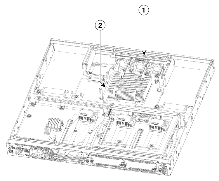
The figure shows the locations of internal components on the motherboard. Internal modules include DIMMs on Cisco 8300 Series Secure Routers.

To access the internal components on the device, you must first remove the chassis cover. For instructions on how to remove and replace the chassis cover on the device, see the sections on Install and Remove Chassis Covers.

Figure 1. Internal component locations in the C8375-E-G2

Sl. No

Modules

1

Fan tray

2

DIMM

Remove and replace the chassis cover

The Cisco 8300 Series Secure Routers have removable covers. Before removing the cover, do these steps:

  • Do not run the device with the cover off. Doing so can cause the chassis to overheat very quickly.

  • Disconnect all power cables.

  • Remove the device from the rack


Warning


Statement 1041—Disconnect Telephone Network Cables

Before opening the unit, disconnect the telephone network cables to avoid contact with telephone network voltages.


Use a number-2 Phillips screwdriver to perform these tasks.

Remove the chassis cover

To remove the cover, perform the following steps.

Procedure

Step 1

Read the Safety Warnings and disconnect the power supply before you perform any module replacement.

Step 2

Confirm the device is turned off and disconnected from the power supply or power supplies. If a redundant power is used, disconnect from the redundant power supply.

Step 3

Place the chassis on a flat surface.

Step 4

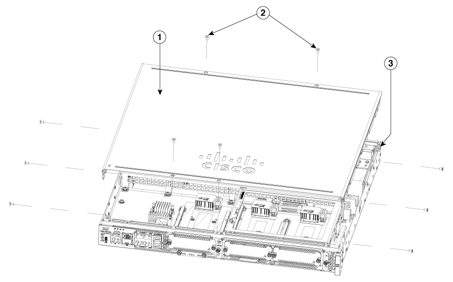
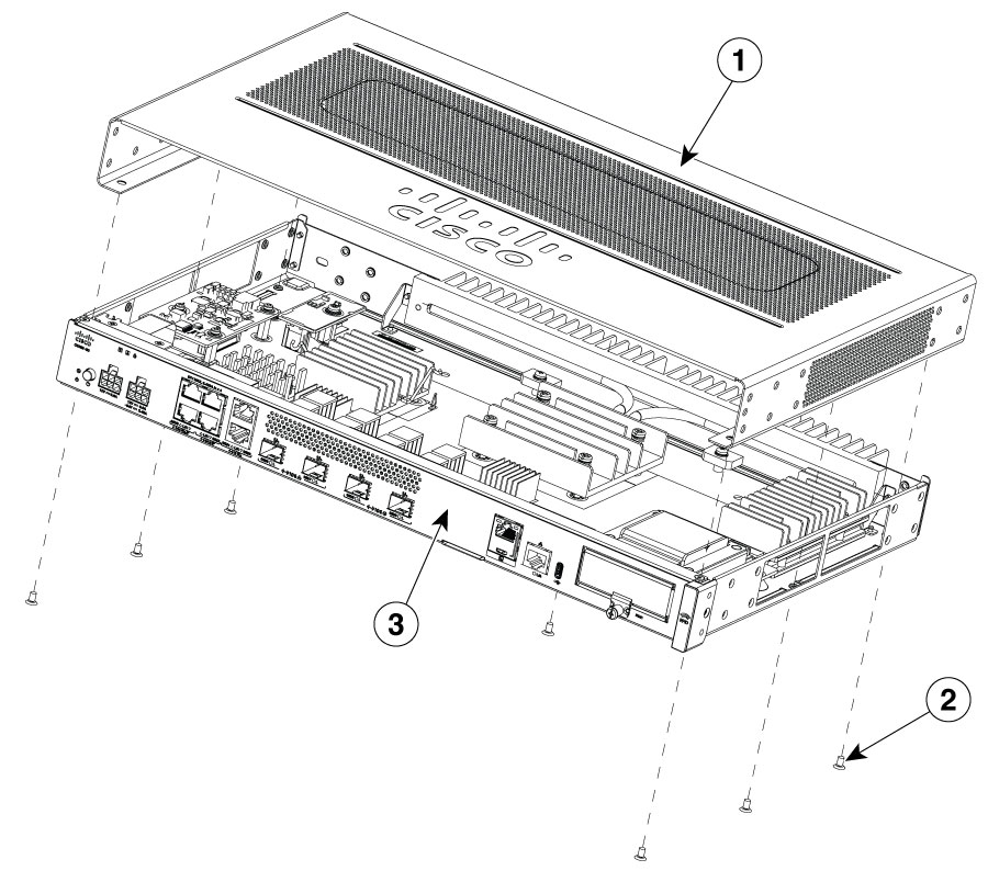
Remove the 11 cover screws.

Step 5

Lift the cover straight up.


Replace the cover

To replace the cover, perform these steps.

Procedure

Step 1

Place the chassis on a flat surface.

Step 2

Drop the cover straight down and ensure that the side flanges insert into the chassis. Care should be taken to not damage the EMC Gaskets.

Step 3

Install the 11 cover screws.

Figure 2. Install the cover on the C8375-E-G2

1

Chassis cover

2

Screws

3

Chassis

Figure 3. Install the cover on the C8355-G2

1

Chassis cover

2

Screws

3

Chassis


Remove and replace DDR DIMMs

To access the DIMMs, you must remove the chassis cover as described in the Access and Install Modules section.


Caution


Always wear an ESD-preventive wrist strap and ensure that it makes good contact with your skin when you remove or install DIMMs. Connect the equipment end of the wrist strap to the metal part of the chassis.


Caution


Handle DIMMs by the edges only. DIMMs are ESD-sensitive components and can be damaged by mishandling.


Locate and orient DIMM

DIMMs have a polarization notch on the mating edge to prevent incorrect insertion. The image shows the polarization notch on a DIMM.

Figure 4. DIMM Showing Polarization Notch

1

Polarization notch

Remove a DIMM

Follow these steps to remove a DIMM:

Procedure


Step 1

Read the Safety Warnings section and disconnect the power supply before you perform any module replacement.

Step 2

If the cover is not already removed, remove the chassis cover.

Step 3

Locate the DIMM module to find the DIMM sockets on the chassis.

Step 4

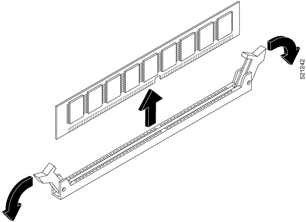
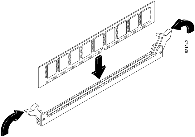
Rotate DIMM connector handles downwards to extract the DIMM module.

Figure 5. Remove a DIMM

Install a DIMM

Follow these steps to install a DIMM on the Cisco 8300 Series Secure Routers.

Procedure


Step 1

Read the Safety Warnings section and disconnect the power supply before you perform any DIMM replacement.

Step 2

If the cover is not already removed, remove the chassis cover.

Step 3

Locate the DIMM module to find the DIMM sockets on the device.

Step 4

Ensure that both latches on the DIMM connector are in the open position.

Step 5

Orient the DIMM so that the polarization notch lines up with the polarization key on the connector.

Figure 6. DIMM showing Polarization Notch

Step 6

Insert the DIMM into the connector one side at a time.

Step 7

Rotate the connector handles upward and click into place.

Step 8

Reinstall the chassis cover.

Figure 7. Install a DIMM

Step 9

Replace the chassis cover.


Remove and replace the power supplies


Warning


Statement 1029—Blank Faceplates and Cover Panels

Blank faceplates and cover panels serve three important functions: they reduce the risk of electric shock and fire, they contain electromagnetic interference (EMI) that might disrupt other equipment, and they direct the flow of cooling air through the chassis. Do not operate the system unless all cards, faceplates, front covers, and rear covers are in place.


Warning


Statement 1028—More Than One Power Supply

This unit might have more than one power supply connection. To reduce risk of electric shock, remove all connections to de-energize the unit.


Warning


Care should be taken while removing the power supplies (especially in boost mode of operation). If the total power consumption is higher than can be supported by one power supply alone and in this condition a power supply is removed, the hardware can be damaged. This may then result in the system being unstable or unusable.

AC power supplies

The Cisco 8300 Series Secure Routers device have two different AC power supply types and they are the same physical size. The power supplies cannot be interchanged.

Overview of the AC power supply

The AC power supplies for the Cisco 8300 Series Secure Routers device are:

  • PWR-CC1-400WAC

  • PWR-CC1-760WAC

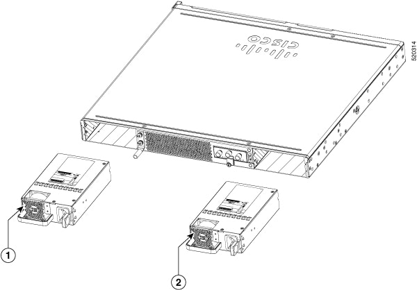
The two supplies are physically similar and a diagram is shown in this figure.

Figure 8. 400W AC power supply for C8375-E-G2

Sl. No

Module

1

PSU1

2

PSU0

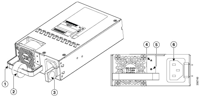
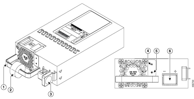
Figure 9. 760W AC power supply for C8375-E-G2

1

Handle

2

Strain relief

3

Latch

4

Fail LED

5

Status LED

6

Power socket

Remove and replace the AC power supply

To remove an AC power supply from the Cisco 8300 Series Secure Routers, perform these steps:

Procedure


Step 1

Read the safety warnings section of this document.

Step 2

If there is only one power supply in the system, shut down the device before removing the power supply.

Step 3

If there are redundant power supplies in use the device does not have to be shut down prior to replacing the power supply. The power supply may be replaced while the device is in service.

Step 4

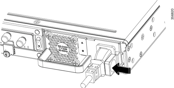
If in use, remove the strain relief securing the power supply cable to the power supply latch.

Step 5

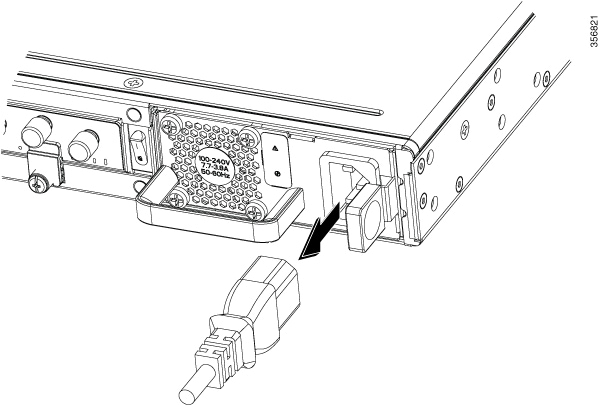
Remove the AC power cord from the power socket.

Step 6

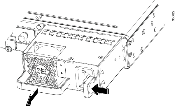
Depress the power supply latch and use the handle to pull the supply out of the device.

Figure 10. Step 4

Figure 11. Step 5

Figure 12. Step 6

To replace or install an AC power supply into the Cisco 8300 Series Secure Routers, perform these steps:

Procedure

Step 1

Use the handle to push the power supply into the router. The power supply latch should provide an audible click when the supply is fully seated.

Step 2

Install the AC power cord into the power socket on the power supply.

Step 3

If used, reapply the strain relief strap around the power cord and the power supply latch.

Step 4

If the device was turned off, turn the power back on to the device.


DC power supplies

The Cisco 8300 Series Secure Routers have one DC power supply type. As with the AC power supplies, the DC power supplies are not of the same size and cannot be interchanged.

Overview of the DC power supplies

The DC power supply for Cisco 8300 Series Secure Routers devices is shown in the figure:

  • PWR-CC1-500WDC

Figure 13. 500WDC power supply for C8375-E-G2

1

Handle

2

Strain relief

3

Latch

4

Fail LED

5

Status LED

6

Terminal block

Remove and Replace the DC Power Supply

To remove a DC power supply from a Cisco 8300 Series Secure Routers, perform these steps:

Procedure


Step 1

Read the safety warnings section of this document.

Step 2

If there is only one power supply in the system, shut down the device before removing the power supply.

Step 3

If there are redundant power supplies in use the device does not have to be shut down prior to replacing the power supply. The power supply may be replaced while the device is in service.

Step 4

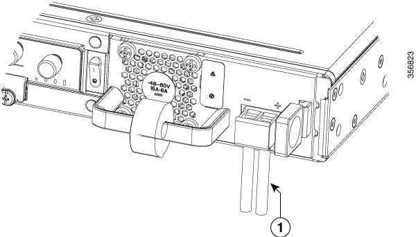
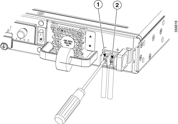
At the power distribution panel or at the local circuit breaker, remove the power from the DC power leads (label 1)attached to the power supply to be replaced.

Step 5

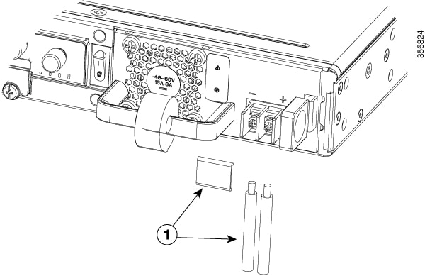
Remove the terminal block cover and loosen the terminal screws (label 1) securing the power cabling. Remove the power cabling from the terminal block.

Step 6

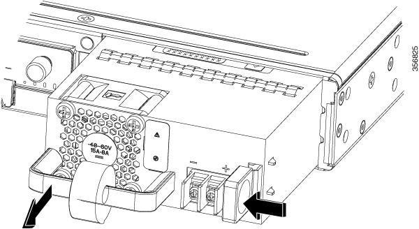
Depress the power supply latch and use the handle to pull the supply out of the device.

Figure 14. Remove a DC Power Supply from the C8375-E-G2

Figure 15. Step 5

Figure 16. Step 6

To replace or install a DC power supply from a C8375-E-G2, perform these steps:

Procedure

Step 1

Use the handle to push the power supply into the router. The power supply latch should provide an audible click when the supply is fully seated.

Step 2

If this is an initial installation, please see the section on preparing the DC power leads below.

Step 3

Install the DC power leads into the terminal block and tighten the terminal block screws to secure the cables. For the PWR-CC1-400WDC power supply the negative lead installs into the left terminal position and the positive lead installs into the right terminal position. The polarity is marked on the faceplate of the power supply.

Caution


Do not over torque the terminal block captive screws. Ensure that the connection is snug, but the wire is not crushed. Verify by tugging lightly on each wire to ensure that they do not move.

Step 4

Reinstall the terminal block cover.

Step 5

If the device was turned off, turn the power back on to the device.


Install the DC input power

This section describes how to install the DC power supply input power leads to the Cisco 8300 Series Secure Routers DC input power supply. Before you begin, read these important notices:

  • The color coding of the DC input power supply leads depends on the color coding of the DC power source at your site. Ensure that the lead color coding you choose for the DC input power supply matches the lead color coding used at the DC power source and verify that the power source is connected to the negative (–) terminal and to the positive (+) terminal on the power supply.

  • Ensure that the chassis ground is connected on the chassis before you begin installing the DC power supply. Follow the steps provided in the Chassis Grounding .


Warning


Statement 1003—DC Power Disconnection

To reduce risk of electric shock or personal injury, disconnect DC power before removing or replacing components or performing upgrades.


Prepare the wire for connecting to the DC power supply

In the Cisco 8300 Series Secure Routers, the DC power supply has a terminal block that is installed into the power supply terminal block header.

Use these steps to prepare the wire for connection to the terminal source:

Procedure


Step 1

Turn off the circuit breaker from the power source to be connected to the power source. Ensure the wires to be attached to the power supply are not energized.

Step 2

The wires connecting to the power supply can be stripped back and terminated directly to the power supply terminal block. Alternately a crimp style spade terminal lug can be attached to the end of the wire. If using a terminal lug, follow the manufacturer's instructions for terminating the lug to the wire. If terminating directly to the terminal block using bare wire, following the directions shown below.

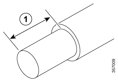
Use a wire-stripping tool to strip each of the two wires coming from the DC input power source to approximately 0.39 inch (10 mm) +/- 0.02 inch (0.5 mm). It is recommended that 14 AWG insulated wire be used. Do not strip more than the recommended length of wire because doing so could leave the wire exposed from the terminal block and shows a stripped DC input power source wire.

Figure 17. Stripped DC input power source wire

1

0.39 inch (10 mm) is the recommended wire-strip length for the terminal block.

Identify the positive and negative feed positions for the terminal block connection of C8375-E-G2:

  1. Positive (+) lead wire (right)

  2. Negative (–) lead wire (left)

Figure 18. DC power supply with lead wires
Table 1.

1

Negative (-) lead wire

2

Positive (+) lead wire


Replace a fan tray for Cisco 8300 Series Secure Routers

In the Cisco 8300 Series Secure Routers, we have fan trays that are field replaceable units (FRUs). The fan tray includes all the fans in one assembly. If a fan fails, replace the tray using a #1 Phillips screwdriver.

Before replacing a fan tray

Read the safety precautions below and have the required tools available before replacing a fan tray:

Remove the Fan Tray from a C8375-E-G2

The C8375-E-G2 supports forward air flow (standard version).

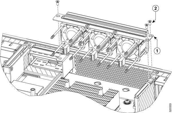
To replace the fan tray, perform these steps:

Procedure

Step 1

Power off the device

Step 2

Remove all cables from the chassis

Step 3

Remove unit from the equipment rack if it is installed in a rack

Step 4

Remove the top cover

Step 5

Remove the three screws from the fantray

Step 6

Disconnect fan cables from the motherboard

Step 7

Remove the fan tray

Note


The estimated time for replacing the fan tray on C8375-E-G2 by a skilled technician within 60 Minutes.

1

Fan tray

2

Screws


Install the Fan Tray into a C8375-E-G2

The C8375-E-G2 supports forward air flow (standard version).

To replace the fan tray, perform these steps:

Procedure

Step 1

Install the fan tray

Step 2

Install the three fan tray mounting screws

Step 3

Connect the fan cables to the motherboard

Step 4

Install the top cover

Step 5

If appropriate, re-install the unit back in an equipment rack

Step 6

Reinstall all cables from the chassis

Step 7

Power on the unit

1

Fan tray

2

Screws


Install and remove SFP and SFP+ Modules

Before you begin

See the Cisco 8300 Series Secure Routers' datasheet for a list of supported SFP and SFP+ modules. Use only supported SFP/SFP+ modules on the platform.


Warning


Statement 1008—Class 1 Laser Product

This product is a Class 1 laser product.


Note


We recommend that you wait 30 seconds between removal and insertion of an SFP on an interface module. This time is recommend to allow the transceiver software to initilize and synchronise with the standby RSP. Chaning an SFP more quickly could result in transceiver initialization issues that disable the SFP


  • Do not remove the dust plugs from the SFP and SFP+ modules or the rubber caps from the fiber-optic cable until you are ready to connect the cable. The plugs and caps protect the module ports and cables from contamination and ambient light.

  • Removing and installing an SFP and SFP+ module can shorten its useful life. Do not remove and insert any SFP/SFP+ module more often than is necessary.

  • To prevent ESD damage, follow your normal board and component handling procedures when connecting cables to the switch and other devices.

  • When you insert several SFP and SFP+ modules in multiple ports, wait for 5 seconds between inserting each SFP/SFP+. This will prevent the ports from going into error disabled mode. Similarly, when you remove an SFP and SFP+ from a port, wait for 5 seconds before reinserting it.

Procedure


Step 1

Attach an ESD-preventive wrist strap to your wrist and to an earth ground surface.

Step 2

Find the send (TX) and receive (RX) markings that identify the top of the SFP/SFP+ module.

On some SFP/SFP+ modules, the send and receive (TX and RX) markings might be shown by arrows that show the direction of the connection.

Step 3

If the SFP/SFP+ module has a bale-clasp latch, move it to the open, unlocked position.

Step 4

Align the module in front of the slot opening, and push until you feel the connector snap into place.

Step 5

If the module has a bale-clasp latch, close it to lock the SFP/SFP+ module in place.

Step 6

Remove the SFP and SFP+ dust plugs and save.

Step 7

Connect the SFP and SFP+ cables.


Laser safety guidelines

Optical Small-Form Pluggable (SFPs) use a small laser to generate the fiber-optic signal. Keep the optical transmit and receive ports covered whenever a cable is not connected to the port.


Warning


Statement 1051—Laser Radiation

Invisible laser radiation may be emitted from disconnected fibers or connectors. Do not stare into beams or view directly with optical instruments.


Warning


Statement 1255—Laser Compliance Statement

Pluggable optical modules comply with IEC 60825-1 Ed. 3 and 21 CFR 1040.10 and 1040.11 with or without exception for conformance with IEC 60825-1 Ed. 3 as described in Laser Notice No. 56, dated May 8, 2019.


To install an SFP module in your device, perform these steps:

Procedure


Step 1

Read the Safety Warnings and disconnect the power supply before you perform any module replacement.

Step 2

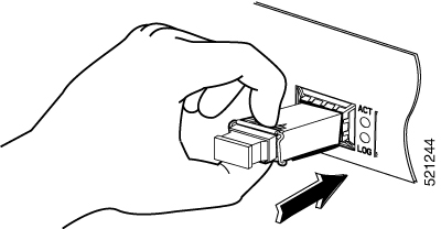
Slide the SFP into the device connector until it locks into position

Tip


If the SFP uses a bale-clasp latch (see Laser Safety Guidelines section, the handle should be on top of the SFP module.

Figure 19. Install a Small-Form Pluggable module

Caution


Do not remove the optical port plugs from the SFP until you are ready to connect cabling.

Step 3

Connect the network cable to the SFP module.


Remove Small Form Pluggable modules

Follow these steps to remove a Small Form Pluggable (SFP) from the device:

Procedure


Step 1

Read the Safety Warnings and disconnect the power supply before you perform any module replacement.

Step 2

Disconnect all cables from the SFP.

Warning


Statement 1051—Laser Radiation

Invisible laser radiation may be emitted from disconnected fibers or connectors. Do not stare into beams or view directly with optical instruments.

Caution

 
The latching mechanism used on many SFPs locks the SFP into place when cables are connected. Do not pull on the cabling in an attempt to remove the SFP.

Step 3

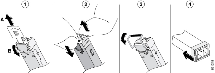
Disconnect the SFP latch.

Note

 
SFP modules use various latch designs to secure the module in the SFP port. Latch designs are not linked to SFP model or technology type. For information on the SFP technology type and model, see the label on the side of the SFP.
Figure 20. Disconnecting SFP latch mechanisms

1

Sliding latch

3

Bale-clasp latch

2

Swing and slide latch

4

Plastic collar latch

Tip


Use a pen, screwdriver, or other small straight tool to gently release a bale-clasp handle if you cannot reach it with your fingers.

Step 4

Grasp the SFP on both sides and remove it from the device.


Remove and replace the USB Flash Token memory stick

The Cisco 8300 Series Secure Routers contain ports for a USB memory stick to store Cisco configurations or Cisco IOS XE consolidated packages.


Caution


Do not remove a USB Flash memory module when issuing some file access command or a read/write operation to the Flash memory module when it is processing. The router might reload or the USB Flash memory module can be damaged. You can check to see if the USB activity LED on the router front panel is flashing, prior to the removal of the USB device


To install, remove a USB memory stick from the device, perform these steps:

Procedure


Step 1

Place the USB stick into the USB port.

Step 2

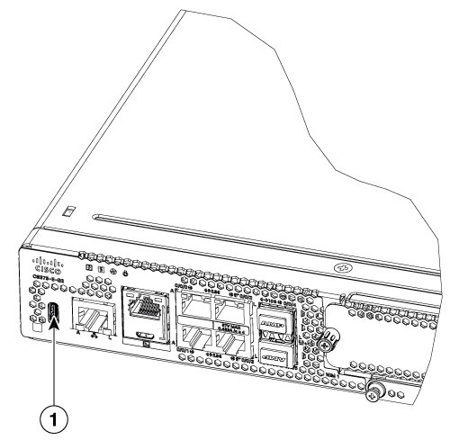
Type-C memory sticks are supported on USB port 1 and type-C memory can be inserted in any direction. Type-A memory sticks are supported on USB port 0 and it must be oriented correctly to allow for proper insertion.

Note

 
A sample of how the memory stick is inserted into the port.
Figure 21. USB memory stick

Note

 
You can insert or remove the memory stick whether the device is powered on or not.

1

USB Type C (3.0) (USB 0)


What to do next

This completes the USB Flash memory installation procedure.

Remove and install an M.2 USB|NVMe module

This section describes installing and replacing an M.2 USB|NVMe module on the Cisco 8300 Series Secure Routers.

Prevent electrostatic discharge damage

The M.2 module is sensitive to electrostatic discharge (ESD) damage, which can occur when electronic cards or components are handled improperly. ESD results in complete or intermittent failures.

To prevent ESD damage, follow these guidelines:

  • Always use an ESD wrist or ankle strap and ensure that it makes good skin contact.

  • Connect the equipment end of the strap to an unfinished chassis surface.

  • Place the M.2 storage devices on an anti-static surface or in a static shielding bag. If you have to return the device to the factory, immediately place it in a static shielding bag.

  • Avoid contact between the device and clothing. The wrist strap protects the device from ESD voltages on the body only; ESD voltages on clothing can still cause damage.

  • Do not remove the wrist strap until the installation is complete.


Caution


For safety, periodically check the resistance value of the anti static strap. The measurement should be between 1 and 10 megohms (Mohms).

Remove the M.2 USB|NVMe module

To remove a M.2 USB|NVMe module, perform these steps:


Note


The M.2 USB|NVMe module installation for C875-E-G2. The M.2 USB|NVMe modules are flipped upside down.


Procedure


Step 1

The device should be powered down and the power supply disconnected before you perform any module replacement.

Step 2

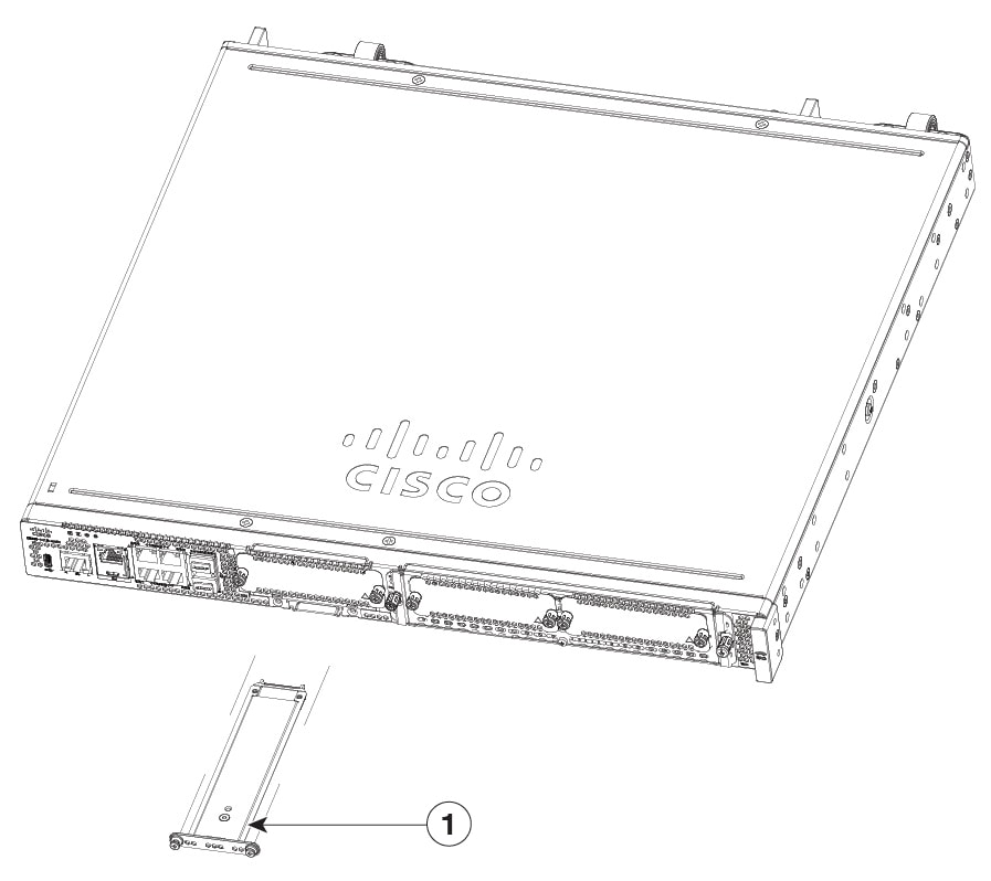
Loosen 2 mounting screws using a #1 Philips screwdriver.

Step 3

Gently pull the M.2 USB|NVMe module out and remove it from the device.

Figure 22. Remove the M.2 USB|NVMe module (C8375-E-G2)

1

M.2 USB|NVMe module


Install the M.2 USB|NVMe module

To install the M.2 USB|NVMe module, perform these steps:


Note


For the C8375-E-G2, the PCB faces down.


Procedure


Step 1

Read all Safety Warnings, ensure that the C8375-E-G2 is not powered on.

Step 2

Insert the M.2 USB|NVMe module into the slot of the device (as shown in the figure). The slide should engage the internal card guides.

Step 3

Gently slide the M.2 USB|NVMe module all the way in until the faceplate is flush with the device.

Step 4

Screw down and tighten the two Philips head screws. Torque it to 4-6 in lbs.

Step 5

The device can now be powered on.

Figure 23. Install the M.2 USB|NVMe (C8375-E-G2)

1

M.2 USB|NVMe


Managing self encrypting drives

Cisco 8300 Series Secure Routers support self-encrypting drives (SED), which helps to enhance the security of data that are stored on these platforms. SEDs are locked using a security key. The security key, which is also known as Key-Encryption Key or an authentication passphrase is used to encrypt the media encryption key. If the disk is not locked, no key is required to retrieve the data. To enable the security lock, use the hw-module harddisk security-lock enable to enable the command. To disable the security lock, use the no hw-module harddisk security-lock enable command.

Also, you can perform these actions:

  • To check the security status, use the show hw-module harddisk security-lock status command.

  • To perform factory reset on the SED when the security-lock is enabled, use the factory-reset sed

  • To perform factory reset on the SED without checkig the status of the security-lock, use the factory-reset sed PSID command. The PSID (Physical Secure ID) is a 32 character ASCII string read from the label attached to the SED drive.