Safety warnings
 Warning |
To comply with Class A emissions requirements- shielded management Ethernet, CON, and AUX cables on the router must be used. |
The documentation set for this product strives to use bias-free language. For the purposes of this documentation set, bias-free is defined as language that does not imply discrimination based on age, disability, gender, racial identity, ethnic identity, sexual orientation, socioeconomic status, and intersectionality. Exceptions may be present in the documentation due to language that is hardcoded in the user interfaces of the product software, language used based on RFP documentation, or language that is used by a referenced third-party product. Learn more about how Cisco is using Inclusive Language.
This chapter describes how to install and connect the Cisco 8300 Series Secure Routers to LAN, WAN, and Voice networks.
 Note |
These routers are designed to boot up in less than 30 minutes, provided the neighboring devices are in fully operational state. |
Warning |
To comply with Class A emissions requirements- shielded management Ethernet, CON, and AUX cables on the router must be used. |
Use the USB or RJ-45 console port on the router to access the Cisco Internet Operating System (IOS-XE) and XE SD-WAN command line interface (CLI) on the router and perform configuration tasks. A terminal emulation program is required to establish communication between the router and a PC. See the Connect to a Console Terminal or Modem section in this document for instructions.
Note |
A Microsoft Windows USB driver must be installed before you establish physical connectivity between the router and the PC. |
To use all the features on the router, you must purchase a software package. For more information on software licenses, see the “Smart Licensing” section of the Software Configuration Guide for the Cisco 8300 Series Secure Routers.
Before installing and connecting a Cisco 8300 Series Secure Routers, read the safety warnings and gather the following tools and equipment. For more information about the required tools and equipments, see the tools and equipment section.
Use the USB or RJ-45 console port on the router to access the Cisco Internet Operating System (IOS-XE) and XE SD-WAN command line interface (CLI) on the router and perform configuration tasks. A terminal emulation program is required to establish communication between the router and a PC. See the Connect to a console terminal or modem section in this document for instructions.
Note |
A Microsoft Windows USB driver must be installed before you establish physical connectivity between the router and the PC. |
To use all the features on the router, you must purchase a software package. For more information on software licenses, see the “Smart Licensing” section of the Software Configuration Guide for the Cisco 8300 Series Secure Routers.
Do not unpack the device until you are ready to install it. If the final installation site will not be ready for some time, keep the chassis in its shipping container to prevent accidental damage. When you are ready to install the chassis, proceed with unpacking it.
The chassis, accessory kit, publications, and any optional equipment you ordered may be shipped in more than one container. When you unpack the containers, check the packing list to ensure that you received all of the items on the list.
If you need to install Network Interface Modules (NIMs), Service Modules (SMs), Pluggable Interface Modules (PIMs), and Field-Replaceable Units (FRUs) on the Cisco 8300 Series Secure Routers, you can install them either before or after you install the device. Ideally, you can install these modules when you have access to the I/O side of the device. Internal modules, memory cards and fan trays should be installed before rack-mounting the device.
You can install the device in one of the following ways:
Set the chassis on a desktop
Attach the chassis to the wall
Mount the chassis on a rack
Note |
C8375-E-G2 support only rack mount, does not support wall mount or desktop mount options. |
 Caution |
To prevent damage to the chassis, do not attempt to lift or tilt the chassis by holding it by the plastic panel on the front. Always hold the chassis by the sides of the metal body. |
Warning |
Statement 1032—Lifting the Chassis To prevent personal injury or damage to the chassis, never attempt to lift or tilt the chassis using the handles on modules, such as power supplies, fans, or cards. These types of handles are not designed to support the weight of the unit. |
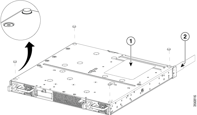
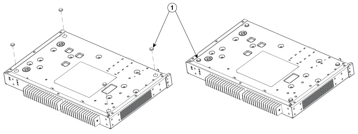
Step 1 Attach the elastomeric mount feet (label 1) to the bottom of the device. The feet come with a pre-applied adhesive. Place the feet in the locations marked by a circle.
Step 2 You can place the device on a desktop, bench top, or shelf.
Note |
Do not set the chassis in an area where the high acoustic noise can be an issue. |
Caution |
Do not place anything on top of the device that weighs more than 10 pounds (4.5 kg), and do not stack device on a desktop. Excessive distributed weight of more than 10 pounds, or pound point load of 10 pounds on top could damage the chassis. |
Caution |
Your chassis installation must allow unrestricted airflow for chassis cooling. For placing the device on a desktop, keep at least 1 inch (2.54 cm) of clear space beside the cooling inlet and exhaust vents. |
After the device is installed, you must connect the chassis to a reliable earth ground. For the chassis ground connection procedures, see the Chassis Grounding section.
Warning |
Statement 1024—Ground Conductor This equipment must be grounded. To reduce the risk of electric shock, never defeat the ground conductor or operate the equipment in the absence of a suitably installed ground conductor. Contact the appropriate electrical inspection authority or an electrician if you are uncertain that suitable grounding is available. |
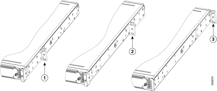
The Cisco 8300 Series Secure Routers can be installed in a 19-inch (48.26-cm) EIA and a 23-inch (58.42-cm) Southwestern Bell Corporation (SBC) racks. It can also be mounted in a 600-mm ETSI rack. Use the standard brackets shipped with the router for mounting the chassis in a 19-inch EIA rack; you can order optional larger brackets for mounting the chassis in a 23-inch SBC rack.
You can mount the devices in the following ways:
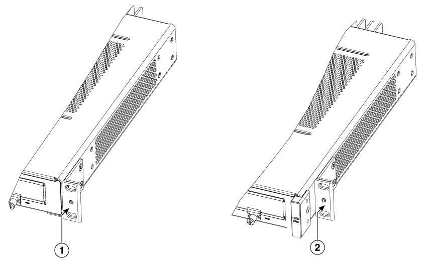
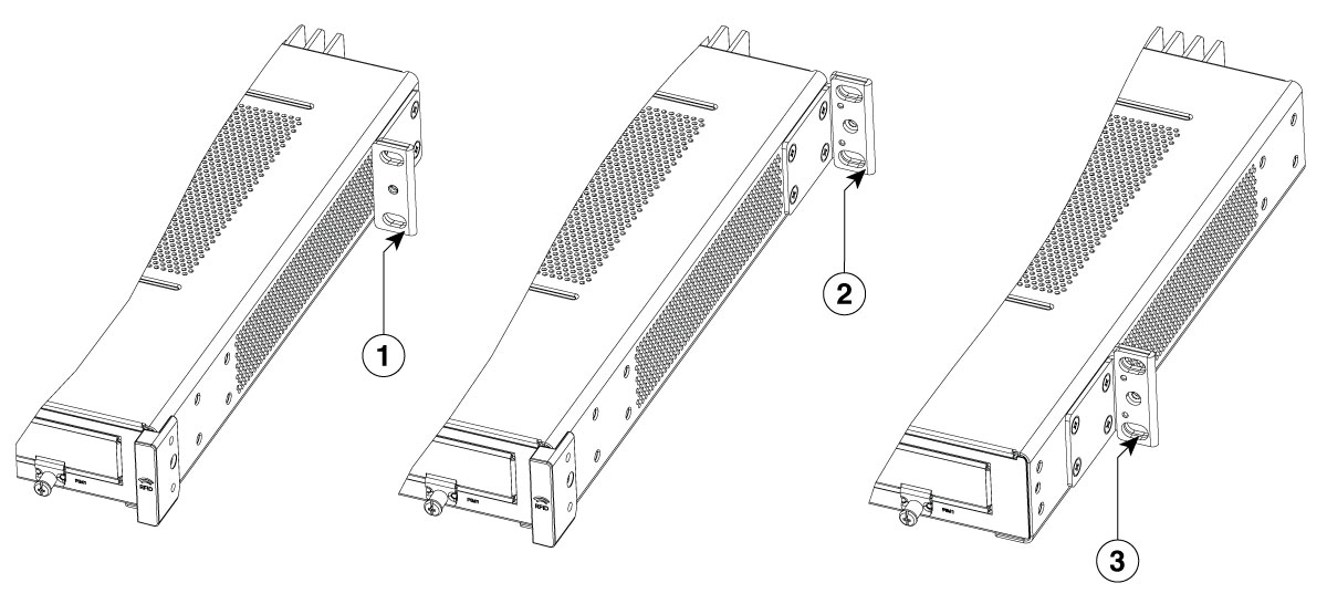
Power Supply (PS) mounting—Brackets are attached at the PS side of the chassis with the front panel facing forward.
Center-PS mounting—Brackets are attached in the centerof the chassis with the PS side facing forward.
Center-I/O mounting—Brackets are attached in the center I/O side of the chassis with only the I/O side facing forward.
I/O mounting—Brackets are attached at the I/O side of the chassis with the I/O side facing forward.
Caution |
Do not over-torque the screws. The recommended torque is 15 to 18 inch-lbs (1.7 to 2.0 N-m). |
Caution |
Your chassis installation must allow unrestricted airflow for chassis cooling. |
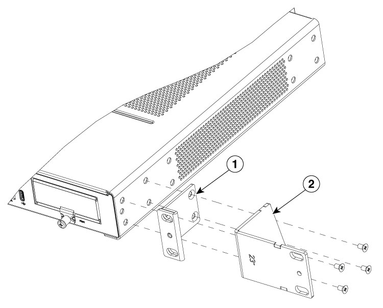
Attach the mounting brackets to the chassis as shown in the below figure using the screws provided. Use a #2 Philips screwdriver.
To attach the rack-mounting brackets to the device, perform these steps:
|
Step 1 |
Select the depth location for the router in the equipment rack. I/O side flush; I/O side recessed for the RFID badge; middle mount from the I/O side; middle mount from the power supply side; or power supply side flush. |
||||||||||||||||||||||||||||||
|
Step 2 |
Align the rack mount bracket with the mounting holes in the side of the device. |
||||||||||||||||||||||||||||||
|
Step 3 |
Insert the #6-32 FHM screws. Use only the screws that are provided in the rack mount bracket kit. |
||||||||||||||||||||||||||||||
|
Step 4 |
Tighten the screws to a torque value of 15 to 18 inch-lb. (1.7 to 2.0 N-m). 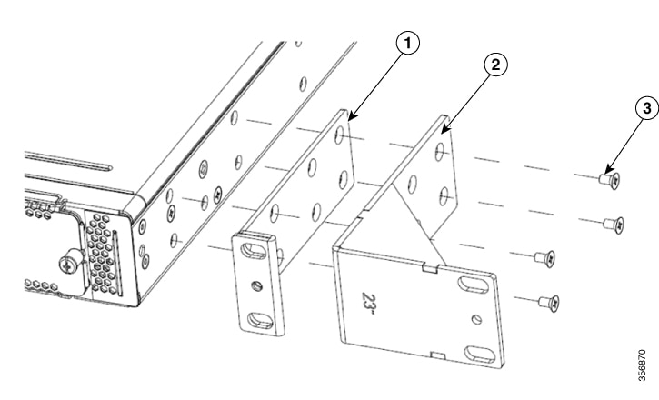
|
After you attach the rack-mount brackets to the chassis, use screws to install the chassis onto the rack.
 Tip |
For both the 19-inch EIA brackets and the 23-inch brackets, start the lower pair of screws first, and rest the brackets on the lower screws while you insert the upper pair of screws. |
Tip |
The screw slots in the brackets are spaced to line up with every second pair of screw holes in the rack. When the correct screw holes are used, the small threaded holes in the brackets line up with unused screw holes in the rack. If the small holes do not line up with the rack holes, you must raise or lower the brackets to the next rack hole. |
Warning |
To prevent bodily injury when mounting or servicing this unit in a rack, you must take special precautions to ensure that the system remains stable. The following guidelines are provided to ensure your safety:
|
Warning |
Statement 1006—Chassis Warning for Rack-Mounting and Servicing To prevent bodily injury when mounting or servicing this unit in a rack, you must take special precautions to ensure that the system remains stable. The following guidelines are provided to ensure your safety:
|
Warning |
Statement 1032—Lifting the Chassis To prevent personal injury or damage to the chassis, never attempt to lift or tilt the chassis using the handles on modules, such as power supplies, fans, or cards. These types of handles are not designed to support the weight of the unit. |
Note |
When mounting C8355-G2 on a rack, ensure at least one rack unit (1RU) of vertical space between routers. This ensures more heat removal, which in turn helps the local air temperature to stay within the specified operating conditions. |
Step1. Locate the desired position in the equipment rack.
Step2. Align the holes in the rack mount brackets with the mounting holes in the equipment frame.
Step3. Secure the device using mounting screws appropriate for your equipment frame. The rack mount brackets have been designed #12-24 PHM screws.
Step4. Tighten the screws to the appropriate torque value for your equipment
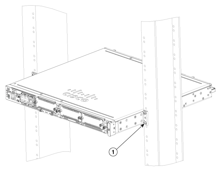
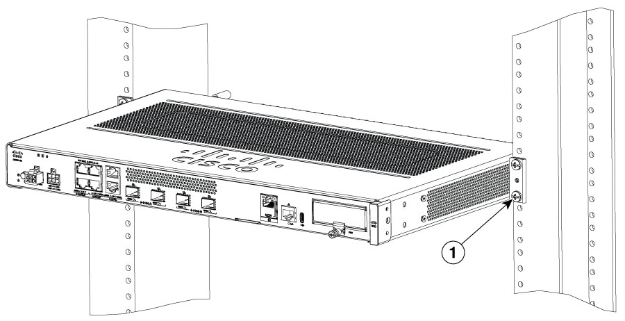
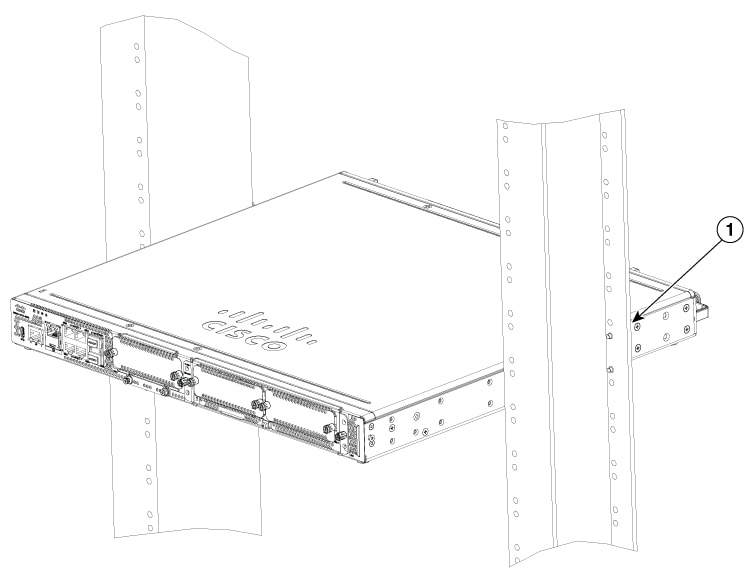
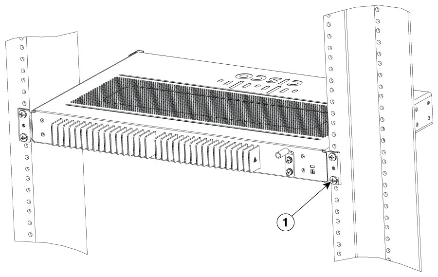
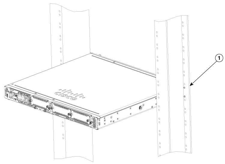
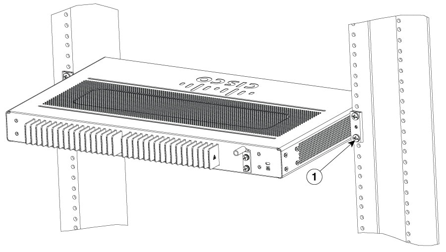
Figures show a typical rack mounting of a chassis in a rack.
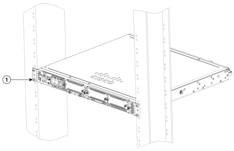
|
1 |
Rack Mounting screws |
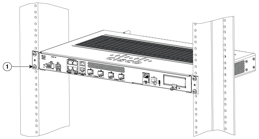
|
1 |
Rack Mounting screws |
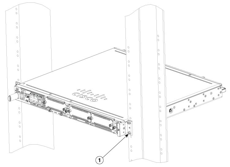
|
1 |
Rack Mounting screws |
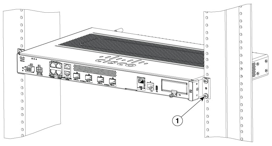
|
1 |
Rack Mounting screws |
|
1 |
Rack Mounting screws |
|
1 |
Rack Mounting screws |
|
1 |
Rack Mounting screws |
|
1 |
Rack Mounting screws |
|
1 |
Rack Mounting screws |
|
1 |
Rack Mounting screws |
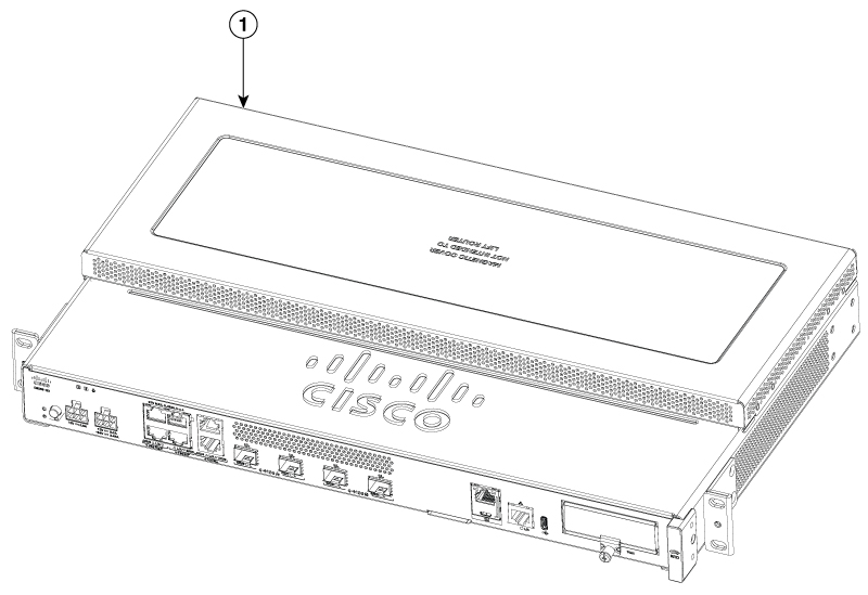
This procedure describes how to attach the top plate on the router chassis:
|
Step 1 |
Orient the top plate on the router as shown in the figure. 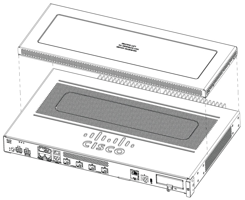
|
||||
|
Step 2 |
Ensure the magnetic top plate is attached securely on the router. 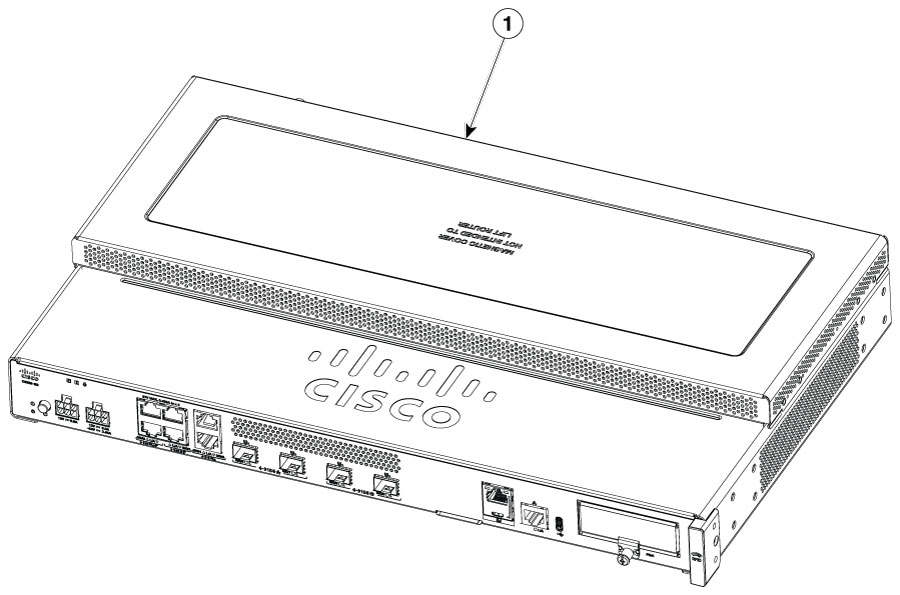
|
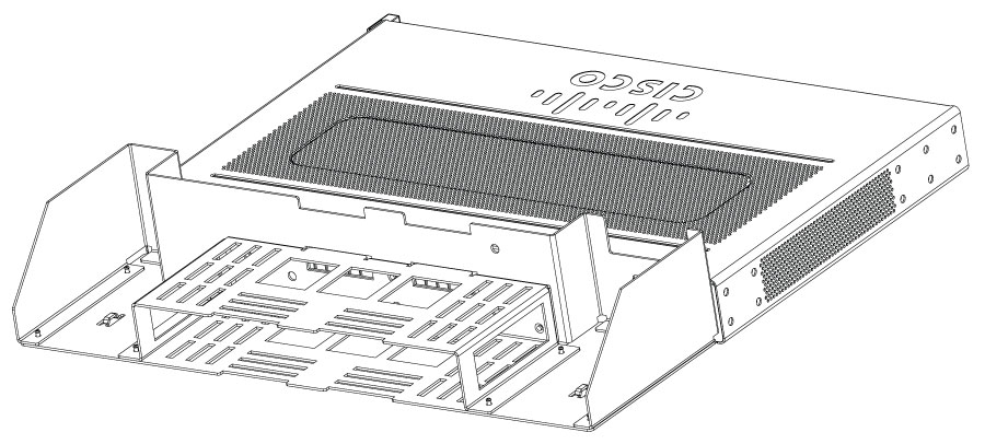
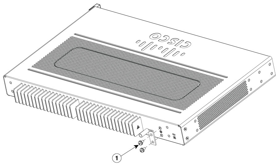
This procedure describes how to attach a power bracket on the router chassis:
Caution |
Ensure that the power adapters are installed in the bracket when the device is rack mounted. Do not place the adapters directly on top of the chassis. |
|
Step 1 |
Orient the power adapter bracket to rear end of the router. |
||||
|
Step 2 |
Secure the brackets to the router chassis as shown in figure: 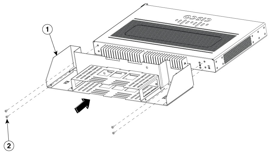
|
Caution |
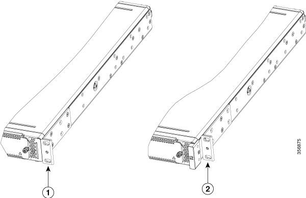
When mounted on a wall, the router should always be oriented with a side of the device oriented in the downward position. The I/O side and power supply side should be oriented so that the fan vents and cable entry will be oriented to the left or right. The I/O side or power supply should never be oriented downwards. |
Caution |
Your chassis installation must allow unrestricted airflow for chassis cooling. |
|
Step 1 |
Attach the rack mount brackets to the sides of the device using only the hardware provided in the wall mounting kit (#6-32 x 0.44 inch PHMS). |
||||||||
|
Step 2 |
The outer face of the rack mount bracket ear, the part that typically mounts to an equipment rack, should be placed against the side of the router. Use the spacers provided to adapt the larger obround holes down to smaller holes for the screws to fit into. |
||||||||
|
Step 3 |
The brackets should be located diagonally from each other as shown in the figure below. |
||||||||
|
Step 4 |
Tighten the screws to a torque value of 15 to 18 inch-lb. (1.7 to 2.0 N-m). |
||||||||
|
Step 5 |
Use #6 or 4mm hardware to attach the brackets to the wall. At least 4 screws should be used per bracket, 8 screws in total. The screw length should be a minimum of 1 inch in length (25.4 mm).
|
||||||||
|
Step 6 |
Route the cables so that they do not put a strain on the connectors or mounting hardware. 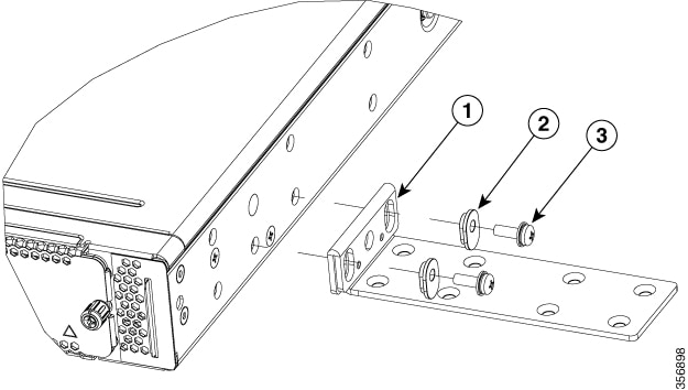
|
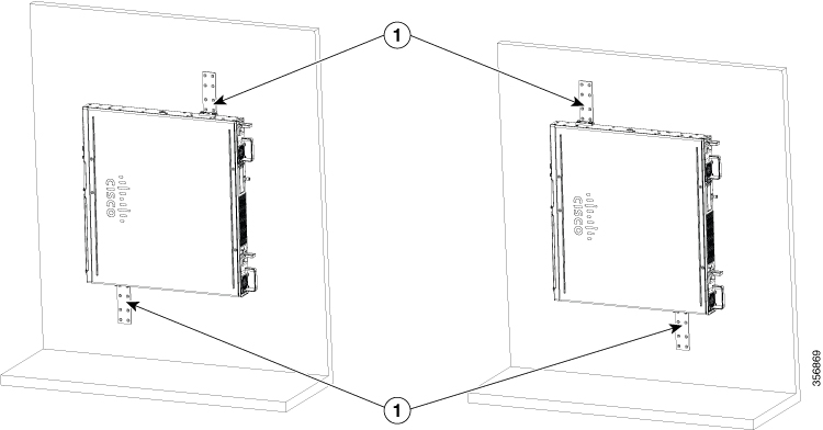
The C8355-G2 routers have key-hole slots at the bottom of the chassis for mounting on a wall or any vertical surface.
Note |
Do not mount the router with the output ports facing downwards. |
Note |
When choosing a location for wall mounting the router, consider cable limitations and wall structure. |
Note |
To attach a router to the wall stud, each bracket should have one number 10 wood screw (pan-head) with number 10 washers, or two number 10 washer-head screws. The screws must be long enough to penetrate at least 1.5 inches (38.1 mm) into the supporting wood or metal wall stud. |
Note |
For hollow-wall mounting, each bracket requires two wall anchors with washers. Wall anchors and washers must be size number 6 (pan-head). Route the cables so that they do not put a strain on the connectors or mounting hardware. |
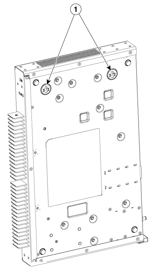
|
1 |
Key-hole slots |
After the device is installed, you must connect the chassis to a reliable earth ground.
Warning |
Statement 1024—Ground Conductor This equipment must be grounded. To reduce the risk of electric shock, never defeat the ground conductor or operate the equipment in the absence of a suitably installed ground conductor. Contact the appropriate electrical inspection authority or an electrician if you are uncertain that suitable grounding is available. |
You must connect the chassis to a reliable earth ground; the ground wire must be installed in accordance with local electrical safety standards.
For grounding, use size 6 AWG (13 mm² ) copper wire and the ground lug provided in the accessory kit.
Note |
This equipment is suitable for installation in Network Telecommunications Facilities and locations where the NEC applies. The equipment is suitable for installation as part of the Common Bonding Network (CBN). |
For NEC-compliant grounding, use size 14 AWG (2 mm² ) or larger copper wire and an appropriate user-supplied ring terminal with an inner diameter of 1/4 in. (5–7 mm)
AWG 10 (4 mm²) or larger wire for EN/IEC 60950-1 and EN/IEC 62368-1 compliant chassis grounding
Note |
The grounding wire should be sized according to local and national installation requirements. The above recommended AWG values for NEBS-compliant, NEC-compliant, EN/IEC 60950-1 and EN/IEC 62368-1 as the minimum requirement respectively, the higher AWG value recommendation also with the higher priority, this means AWG 10 is the minimum requirement only when NEBS is not required. Commercially available 6-AWG grounding wire is always preferred from the chassis to the rack ground or directly to the common bonding network (CBN). The length of the grounding wire depends on the proximity of the switch to proper grounding facilities. |
To install the ground connection for your device, perform the following steps:
|
Step 1 |
Strip one end of the ground wire to the length required for the ground lug or terminal.
|
||
|
Step 2 |
Crimp the ground wire to the ground lug or ring terminal, using a crimp tool of the appropriate size. |
||
|
Step 3 |
Attach the ground lug or ring terminal to the chassis as shown in Chassis Grounding section. For a ground lug, use the two screws with captive locking washers provided. For a ring terminal, use one of the screws provided. Tighten the screws to a torque of 8 to 10 in-lb (0.9 to 1.1 N-m). 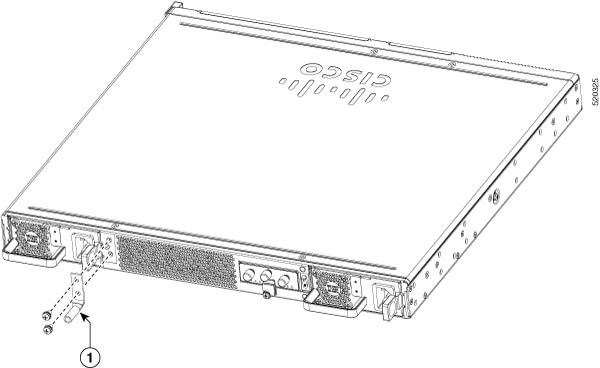
|
||
|
Step 4 |
Connect the other end of the ground wire to a known reliable earth ground point at your site. |
This section explains how to connect power to the device.
Warning |
Statement 1028—More Than One Power Supply This unit might have more than one power supply connection. To reduce risk of electric shock, remove all connections to de-energize the unit.  |
Note |
The installation must comply with all required electrical codes applicable at the installation site. |
If your device uses AC power, connect it to a 15 A, 120 VAC (10 A, 240 VAC) circuit with overcurrent protection.
Note |
The input voltage tolerance limits for AC power are 90 and 264 VAC. |
Note |
This product requires surge protection to be provided as part of the building installation. To comply with the Telcordia GR-1089 NEBS standard for electromagnetic compatibility and safety, an external surge protective device (SPD) is required at the AC power service equipment. |
Warning |
Statement 1005—Circuit Breaker This product relies on the building’s installation for short-circuit (overcurrent) protection. To reduce risk of electric shock or fire, ensure that the protective device is rated not greater than: 20A. |
The Cisco 8300 Series Secure Routers have asynchronous serial ports. These ports provide administrative access to the router either locally (with a console terminal or a PC).To configure the router through the Cisco IOS CLI, you must establish a connection between the router console port and either a terminal or a PC.
Use these cables and adapters to establish a local or remote connection.
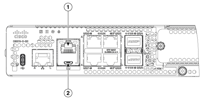
|
Port Type |
Cable |
Section |
|
1. Serial (RJ-45) |
EIA RJ-45 |
Connect to the Serial Port with Microsoft Windows |
|
2. Serial (USB) |
USB 5-pin mini USB Type-B-to-USB Type-A |
|
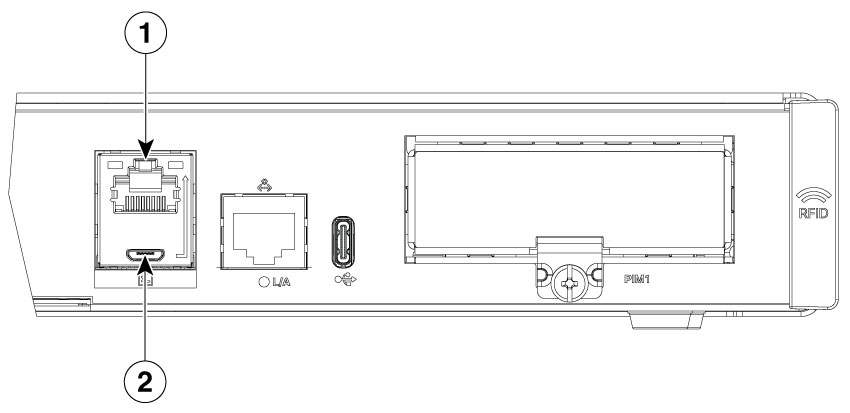
Port Type |
Cable |
Section |
|
1. Serial (RJ-45) |
EIA RJ-45 |
Connect to the Serial Port with Microsoft Windows |
|
2. Serial (USB) |
USB 5-pin mini USB Type-B-to-USB Type-A |
This procedure describes how to connect a Mac OS X system USB port to the console using the built in OS X Terminal utility.
|
Step 1 |
Use the Finder to go to Applications > Utilities > Terminal. |
|
Step 2 |
Connect the OS X USB port to the router. |
|
Step 3 |
Enter the commands to find the OS X USB port number Example: |
|
Step 4 |
Connect to the USB port with the command followed by the router USB port speed Example:To disconnect the OS X USB console from the terminal window Enter Ctrl-a followed by Ctrl-\ |
This procedure shows how to connect a Linux system USB port to the console using the built in Linux Terminal utility.
|
Step 1 |
Open the Linux Terminal window. |
|
Step 2 |
Connect the Linux USB port to the router. |
|
Step 3 |
Enter the commands to find the Linux USB port number Example: |
|
Step 4 |
Connect to the USB port with the command followed by the router USB port speed Example:To disconnect the Linux USB console from the Terminal window Enter Ctrl-a followed by : then quit |
This section contains these topics:
|
Step 1 |
Go to the Silicon Labs website ( www.silabs.com/developers/usb-to-uart-bridge-vcp-drivers?tab=downloads), and click CP210x Universal Windows Driver. |
|
Step 2 |
Unzip the downloaded folder, and select the installer for your system configuration. The Device Driver Installation Wizard begins. |
|
Step 3 |
Click Next on the Installation Wizard, then click Finish to complete installation. |
|
Step 4 |
Open the Device Manager on your system and click the Ports (COM & LPT) drop-down. |
|
Step 5 |
Insert the USB console cable and power into your system. The Device manager refreshes and indicates the newly-detected COM port. |
|
Step 6 |
Open a terminal emulator and click the Serial connection type. Input the values for Serial Line and Speed (or Baud Rate). |
|
Step 7 |
Click Open. |
|
Step 8 |
The terminal emulator opens. Click Enter to view the console output response. The USB console is ready for use. |
|
Step 1 |
Go to the Silicon Labs website (www.silabs.com/developers/usb-to-uart-bridge-vcp-drivers?tab=downloads), and click CP210x VCP Mac OSX Driver. |
|
Step 2 |
Click the Downloads folder, then click the macOS_VCP_Driver folder, and double-click the SiLabsUSBDriverDisk.dmg program. |
|
Step 3 |
Click Install CP210X VCP Driver, and then click Open. The Driver Installer begins. |
|
Step 4 |
Follow installer instructions. Click Continue, scroll all the way down, then click Continue, and click Agree. |
|
Step 5 |
Click Continue, and enter your password. Then click Install Helper, and click Close. |
|
Step 6 |
Insert the USB console cable and power into your system.. |
|
Step 7 |
Open a terminal and type cd/dev, and then type ls-ltr. Serial port tty.SLAB_USBtoUART appears. |
|
Step 8 |
Type screen/dev/tty.SLAB_USBtoUART <baudrate> to see console output. Console will show response upon first Enter key if there is no output. The USB console is ready for use. |
This section describes how to connect WAN and LAN interface cables.
The connections summarized here are also described in detail in the document on Cisco Modular Access Cable Specifications .
|
Port or Connection |
Port Type, Color1 |
Connection: |
Cable |
|---|---|---|---|
|
Ethernet |
RJ-45, yellow |
Ethernet hub or Ethernet switch |
Category 5 or higher Ethernet |
|
T1/E1 WANxCE1T1-PRI |
RJ-48C/CA81ARJ-48S, tan |
T1 or E1 networkExternal T1 CSU or other T1 equipment |
RJ-48 T1/E1RJ-48S to RJ-48S TERJ-48S to RJ-48S NTRJ-48S to RJ-48S T1RJ-48S to bareRJ-48S to BNCRJ-48S to twinaxial cableRJ-48S to DB-15RJ-48S to DB-15 null |
|
T3/DS3/E3 WAN |
BNC connector |
T3 network, CSU/DSU, or other T3/DS3 equipment |
75-ohm coaxial cable |
|
Cisco serial |
60-pin D-sub, blue |
CSU/DSU and serial network or equipment |
Cisco serial transition cable that matches the signaling protocol (EIA/TIA-232, EIA/TIA-449, V.35, X.21, or EIA-530) and the serial port operating mode (DTE or DCE).2 |
|
Cisco Smart serial |
Cisco Smart compact connector, blue |
CSU/DSU and serial network or equipment |
|
|
Gigabit Ethernet SFP, optical |
LC, color according to optical wavelength |
1000BASE-SX, -LX, -LH, -ZX, -CWDM |
Optical fiber as specified on applicable data sheet |
|
Gigabit Ethernet SFP, copper |
RJ-45 |
1000BASE-T |
Category 5, 5e, 6 UTP |
|
Gigabit Ethernet SFP+, optical |
LC, color according to optical wavelength |
10G-SR, -LR, -ER, -DWDM,-AOC,-CU |
Optical fiber as specified on applicable data sheet |
|
Gigabit Ethernet SFP+, copper |
RJ-45 |
10GBASE-T |
Category 6, Category 7 |
Connect each WAN and LAN to the appropriate connector on the chassis or on a network module or interface card.
Position the cables carefully, so that they do not put strain on the connectors.
Organize cables in bundles so that cables do not intertwine.
Inspect the cables to make sure that the routing and bend radius is satisfactory. Reposition cables, if necessary.
Install cable ties in accordance with site requirements.
For cable pinouts, see Cisco Modular Access Cable Specifications.
Note |
After installing the device and connecting the cables, you can configure the device with basic configurations. For more information on how to configure the device, see the Cisco 8300 Series Secure Routers Software Configuration Guide. |
 Feedback