Systems and Interfaces Configuration Guide, Cisco SD-WAN Release 20.x
Bias-Free Language
The documentation set for this product strives to use bias-free language. For the purposes of this documentation set, bias-free is defined as language that does not imply discrimination based on age, disability, gender, racial identity, ethnic identity, sexual orientation, socioeconomic status, and intersectionality. Exceptions may be present in the documentation due to language that is hardcoded in the user interfaces of the product software, language used based on RFP documentation, or language that is used by a referenced third-party product. Learn more about how Cisco is using Inclusive Language.
In the Cisco Catalyst SD-WAN overlay network design, interfaces are associated with VPNs. The interfaces that participate in a VPN are configured and
enabled in that VPN. Each interface can be present only in a single VPN.
At a high level, for an interface to be operational, you must configure an IP address for the interface and mark it as operational
(no shutdown). In practice, you always configure additional parameters for each interface.
You can configure up to 512 interfaces on a Cisco vEdge device. This number includes physical interfaces, loopback interfaces, and subinterfaces.
Note
To maximize the efficiency of the load-balancing among Cisco Catalyst SD-WAN Controllers, use sequential numbers when assigning system IP addresses to the Cisco vEdge devices in the domain. Example of a sequential numbering schemes is 172.16.1.1, 172.16.1.2, 172.16.1.3, and so on.
Note
Ensure that any network interface configured on a device has a unique IP address. If the IP address of the interface conflicts with the system IP address of Cisco SD-WAN Manager instance, it can break the NETCONF session and lead Cisco SD-WAN Manager to read the device as offline.
Note
If you try to configure an interface or sub-interface beyond the supported limit, the device generates a notification to Cisco SD-WAN Manager.
Configure VPN
VPN
Use the VPN template for all Cisco Catalyst SD-WAN devices running the Cisco Catalyst SD-WAN software.
To configure VPNs using Cisco SD-WAN Manager templates, follow this general workflow:
Create VPN feature templates to configure VPN parameters. You create a separate VPN feature template for each VPN. For example,
create one feature template for VPN 0, a second for VPN 1, and a third for VPN 512.
For Cisco SD-WAN Manager Network Management Systems and Cisco Catalyst SD-WAN Controllers, you can configure only VPNs 0 and 512. Create templates for these VPNs only if you want to modify the default settings
for the VPN. For Cisco vEdge devices, you can create templates for these two VPNs and for additional VPN feature templates to segment service-side user networks.
VPN 0—Transport VPN, which carries control traffic via the configured WAN transport interfaces. Initially, VPN 0 contains all of a device's interfaces
except for the management interface, and all interfaces are disabled.
VPN 512—Management VPN, which carries out-of-band network management traffic among the Cisco vEdge devices in the overlay network. The interface used for management traffic resides in VPN 512. By default, VPN 512 is configured
and enabled on all Cisco vEdge devices except for Cisco vEdge 100. For controller devices, by default, VPN 512 is not configured.
VPNs 1–511, 513–65525—Service VPNs, for service-side data traffic on Cisco vEdge devices. For details, see the VRF range behavior change described here.
Create interface feature templates to configure the interfaces in the VPN.
Create a VPN Template
Note
You can configure a static route through the VPN template.
Procedure
Step 1
From the Cisco SD-WAN Manager menu, choose Configuration > Templates.
Step 2
Click DeviceTemplates, and click Create Template.
Note
In Cisco vManage Release 20.7.x and earlier releases Device Templates is called Device.
Step 3
From the Create Template drop-down list, choose From Feature Template.
Step 4
From the Device Model drop-down list, choose the type of device for which you wish to create the template.
Step 5
To create a template for VPN 0 or VPN 512:
Click Transport & Management VPN, or scroll to the Transport & Management VPN section.
From the VPN 0 or VPN 512 drop-down list, click Create Template. The VPN template form appears.
The form contains fields for naming the template, and fields for defining VPN parameters.
Step 6
To create a template for VPNs 1 through 511, and 513 through 65530:Create a template for VPNs. Range: 1 to 65525, excluding 512. For details see the VRF range behavior change described here.
Click Service VPN, or scroll to the Service VPN section.
Click the Service VPN drop-down list.
From the VPN drop-down list, click Create Template. The VPN template form displays.
The form contains fields for naming the template, and fields for defining VPN parameters.
Step 7
In Template Name, enter a name for the template. The name can be up to 128 characters and can contain only alphanumeric characters.
Step 8
In Template Description, enter a description of the template. The description can be up to 2048 characters and can contain only alphanumeric characters.
Configure Service VPN Using Configuration Groups
This feature helps you configure a service VPN (Range: 1 to 65525, excluding 512. For details see the VRF range behavior change described here.) or the LAN VPN.
The following tables describes the options for configuring the Service VPN feature.
Before you begin
On the Configuration > Configuration Groups page, choose SD-WAN as the solution type.
Procedure
Step 1
From the Cisco SD-WAN Manager menu, choose Configuration > Configuration Groups.
Step 2
Create and configure Service VPN in a Service profile.
Enter the basic configuration information.
Table 1. Basic Configuration
Field
Description
VPN*
Enter the numeric identifier of the VPN.
Name*
Enter a name for the VPN.
OMP Admin Distance IPv4
Administrative distance for OMP routes. The Cisco SD-WAN Controllers learn the topology of the overlay network and the services available in the network using OMP routes. The distance can be
a value between 1–255.
OMP Admin Distance IPv6
Administrative distance for OMP routes. The Cisco SD-WAN Controllers learn the topology of the overlay network and the services available in the network using OMP routes. The distance can be
a value between 1–255.
Enter DNS information.
Table 2. DNS
Field
Description
Add DNS IPv4
Primary DNS Address (IPv4)
Enter the IP address of the primary IPv4 DNS server in this VPN.
Secondary DNS Address (IPv4)
Enter the IP address of a secondary IPv4 DNS server in this VPN.
Add DNS IPv6
Primary DNS Address (IPv6)
Enter the IP address of the primary IPv6 DNS server in this VPN.
Secondary DNS Address (IPv6)
Enter the IP address of a secondary IPv6 DNS server in this VPN.
Enter host happing information.
Table 3. Host Mapping
Field
Description
Add New Host Mapping
Hostname*
Enter the hostname of the DNS server. The name can be up to 128 characters.
List of IP*
Enter up to eight IP addresses to associate with the hostname. Separate the entries with commas.
Enter advertise OMP information.
Table 4. Advertise OMP
Field
Description
Add OMP Advertise IPv4
Protocol
Choose a protocol to configure route advertisements to OMP, for this VPN:
bgp
ospf
ospfv3
connected
static
network
aggregate
Applied to Region: (Minimum supported release: Cisco Catalyst SD-WAN Manager Release 20.13.1) In a Multi-Region Fabric scenario, route aggregation is a method for reducing the number of entries that routers in a network
must maintain in routing tables, for better scaling. Choose core, access, or core-and-access, to apply route aggregation only to access regions, the core region, or both.
This option is applicable only to a Multi-Region Fabric border router, not an edge router or a transport gateway.
eigrp
lisp
isis
Select Route Policy
Enter the name of the route policy.
Route policy is not supported in Cisco vManage Release 20.9.1.
Add OMP Advertise IPv6
Protocol
Note
Advertising IPv6 OMP routes as network statements is not supported. This applies when using the Service VPN feature in a configuration
group, and applies also when using a Cisco VPN feature template. You can configure to advertise:
IPv6 routes by BGP and OSPF protocols
Connected routes, static routes, and aggregate routes
The reason for the lack of support is that the Service VPN feature and the Cisco VPN feature template both use the advertise networkprefix command, which does not fully support IPv6 addresses.
Choose a protocol to configure route advertisements to OMP, for this VPN:
BGP
OSPF
Connected
Static
Network
Aggregate
Applied to Region: (Minimum supported release: Cisco Catalyst SD-WAN Manager Release 20.13.1) In a Multi-Region Fabric scenario, route aggregation is a method for reducing the number of entries that routers in a network
must maintain in routing tables, for better scaling. Choose core, access, or core-and-access, to apply route aggregation only to access regions, the core region, or both.
This option is applicable only to a Multi-Region Fabric border router, not an edge router or a transport gateway.
Select Route Policy
Enter the name of the route policy.
Route policy is not supported in Cisco vManage Release 20.9.1.
Protocol Sub Type
When you choose the OSPF protocol, specify the sub type as external.
Enter route information.
Table 5. Route
Field
Description
Add IPv4 Static Route
Network Address*
Enter the IPv4 address or prefix, in decimal four-point-dotted notation, and the prefix length of the IPv4 static route to
configure in the VPN.
Subnet Mask*
Enter the subnet mask.
Next Hop/Null 0/VPN/DHCP
Choose one of the following options to configure the next hop to reach the static route:
Next Hop: When you choose this option, the IPv4 Route Gateway Next Hop field appears. Enable this option to add the next hop. You can add a hop with and without a tracker.
When you click Add Next Hop, the following fields appear:
Address*: Enter the next-hop IPv4 address.
Administrative Distance*: Enter the administrative distance for the route.
When you click Add Next Hop with Tracker, the following fields appear:
Address*: Enter the next-hop IPv4 address.
Administrative Distance*: Enter the administrative distance for the route.
Tracker*: Enter the name of the gateway tracker to determine whether the next hop is reachable before adding that route to the route
table of the device.
Null 0: When you choose this option, the following field appears:
IPv4 Route Null 0*: Enable this option to set the next hop to be the null interface. All packets sent to this interface are dropped without
sending any ICMP messages.
VPN: When you choose this option, the following field appears:
IPv4 Route VPN*: Selects VPN as the gateway to direct packets to the transport VPN.
DHCP: When you choose this option, the following field appears:
IPv4 Route Gateway DHCP*: Assigns a static route for the default next-hop router when the DHCP server is accessed for an IP address.
Add BGP Routing
Choose a BGP route.
Add OSPF Routing
Choose an OSPF route.
Add IPv6 Static Route
Prefix*
Enter the IPv6 address or prefix, in decimal four-point-dotted notation, and the prefix length of the IPv6 static route to
configure in the VPN.
Next Hop/Null 0/NAT
Choose one of the following options to configure the next hop to reach the static route:
Next Hop: When you choose this option and click Add Next Hop, the following fields appear:
Address*: Enter the next-hop IPv6 address.
Administrative distance*: Enter the administrative distance for the route.
Null 0: When you choose this option, the following field appears:
IPv6 Route Null 0*: Enable this option to set the next hop to be the null interface. All packets sent to this interface are dropped without
sending any ICMP messages.
NAT: When you choose this option, the following field appears:
IPv6 NAT*: Choose NAT64 or NAT66.
Interface: When you choose this option, the following fields appear:
Interface Name: Choose IPv6 interface name for the IPsec tunnel.
Next Hop: Enter the IPv6 address and the administrative distance for the next hop.
Enter service information.
Table 6. Service
Field
Description
Add Service
Service Type
Choose a service available at the local site and in the VPN.
Values: FW, IDS, IDP, netsvc1, netsvc2, netsvc3, netsvc4, TE, SIG
IPv4 Addresses (Maximum: 4)*
Enter up to four IP address, separated by commas. The service is advertised to the Cisco SD-WAN Controller only if one of the addresses can be resolved locally, at the local site, not via routes learned through OMP. You can configure
up to four IP addresses.
Tracking*
Cisco Catalyst SD-WAN tests each service device periodically to check whether it is operational. Tracking saves the results of the periodic tests
in a service log.
Tracking is enabled by default.
Enter service route information.
Table 7. Service Route
Field
Description
Add Service Route
Prefix*
Enter the IP address or prefix. For Umbrella SIG, use any RFC 1918 subnet for Service IP addresses.
Enter the IP address or prefix, in decimal four-part-dotted notation, and prefix length of the GRE-specific static route.
Interface*
Enter the name of one or two GRE tunnels to use to reach the service.
VPN*
Enter the number of the VPN to reach the service. This must be VPN 0.
Enter IPSEC route information.
Table 9. IPSEC Route
Field
Description
Add ipSec Route
Prefix*
Enter the IP address or prefix, in decimal four-part-dotted notation, and prefix length of the IPsec-specific static route.
Interface*
Enter the name of one or two IPsec tunnel interfaces. If you configure two interfaces, the first is the primary IPsec tunnel,
and the second is the backup. All packets are sent only to the primary tunnel. If that tunnel fails, all packets are then
sent to the secondary tunnel. If the primary tunnel comes back up, all traffic is moved back to the primary IPsec tunnel.
Enter NAT information
Table 10. NAT
Field
Description
Nat Pool
NatPool Name*
Enter a NAT pool number configured in the centralized data policy. The NAT pool name must be unique across VPNs and VRFs.
You can configure up to 31 (1–32) NAT pools per router.
Prefix Length*
Enter the NAT pool prefix length.
Range Start*
Enter a starting IP address for the NAT pool.
Range End*
Enter a closing IP address for the NAT pool.
Overload*
Enable this option to configure per-port translation. If this option is disabled, only dynamic NAT is configured on the end
device. Per-port NAT is not configured.
Default: Enabled
Direction*
Choose the NAT direction.
Nat64 V4 Pool
Nat64 V4 Pool Name*
Enter a NAT pool number configured in the centralized data policy. The NAT pool name must be unique across VPNs and VRFs.
You can configure up to 31 (1–32) NAT pools per router.
Nat 64 V4 Pool Range Start*
Enter a starting IP address for the NAT pool.
Nat 64 V4 Pool Range End*
Enter a closing IP address for the NAT pool.
Overload*
Enable this option to configure per-port translation. If this option is disabled, only dynamic NAT is configured on the end
device. Per-port NAT is not configured.
Default: Disabled
Enter route leak information.
Table 11. Route leak from Global VPN
Field
Description
Route Protocol*
Choose a protocol to configure leak routes from global VPN to the service VPN that you are configuring:
static
connected
bgp
ospf
Select Route Policy
Choose a route policy from the drop-down list.
Redistribution (in service VPN)
Protocol*
Choose a protocol from the available options to redistribute the leaked routes:
When you first open a feature template, for each parameter that has a default value, the scope is set to Default (a ), and the default setting or value is shown. To change the default or to enter a value, click the scope drop-down list and
select one of the following:
Parameter Name
Description
Device Specific
Use a device-specific value for the parameter. For device-specific parameters, you cannot enter a value in the feature template.
You enter the value when you attach a device to a device template.
When you click Device Specific, the Enter Key box opens. This box displays a key, which is a unique string that identifies the parameter in a CSV file that you create.
This file is an Excel spreadsheet that contains one column for each key. The header row contains the key names (one key per
column), and each row after that corresponds to a device and defines the values of the keys for that device. You upload the
CSV file when you attach a device to a device template. For more information, see Create a Template Variables Spreadsheet
Note
When you are using a CSV file for configuring device-specific variables in the device attach flow, ensure to fill all the
mandatory fields before uploading.
To change the default key, type a new string and move the cursor out of the Enter Key box.
Examples of device-specific parameters are system IP address, hostname, GPS location, and site ID.
Global
Enter a value for the parameter, and apply that value to all devices.
Examples of parameters that you might apply globally to a group of devices are DNS server, syslog server, and interface MTUs.
Once you have created and named the template, enter the following values. Parameters marked with an asterisk are required.
Configure Basic VPN Parameters Using a Configuration Group
Before you begin
On the Configuration > Configuration Groups page, choose SD-WAN as the solution type.
Procedure
Step 1
From the Cisco SD-WAN Manager menu, choose Configuration > Configuration Groups.
Step 2
Create and configure a Transport VPN feature in Transport and Management profile.
Basic Configuration
Table 13. Basic Configuration
Field
Description
VPN
Enter the numeric identifier of the VPN.
Enhance ECMP Keying
Enable the use in the ECMP hash key of Layer 4 source and destination ports, in addition to the combination of the source
IP address, destination IP address, protocol, and DSCP field, as the ECMP hash key.
To configure basic VPN parameters, choose Basic Configuration and then configure the following parameters. Parameters marked with an asterisk are required to configure a VPN.
Parameter Name
Description
VPN
Enter the numeric identifier of the VPN.
Range: 1 to 65525, excluding 512. For details see the VRF range behavior change described here.
Range for Cisco vEdge devices: 0 through 65530
Name
Enter a name for the VPN.
Enhance ECMP keying
Click On to enable the use in the ECMP hash key of Layer 4 source and destination ports, in addition to the combination of the source
IP address, destination IP address, protocol, and DSCP field, as the ECMP hash key.
ECMP keying is Off by default.
Enable TCP Optimization
Cisco vEdge devices only
Click On to enable TCP optimization for a service-side VPN (a VPN other than VPN 0 and VPN 512). TCP optimization fine-tunes TCP to
decrease round-trip latency and improve throughput for TCP traffic.
Note
To complete the configuration of the transport VPN on a router, you must configure at least one interface in VPN 0.
To save the feature template, click Save.
Configure DNS and Static Hostname Mapping Using a Configuration Group
Before you begin
On the Configuration > Configuration Groups page, choose SD-WAN as the solution type.
Procedure
Step 1
From the Cisco SD-WAN Manager menu, choose Configuration > Configuration Groups.
Step 2
Create and configure a Transport VPN feature in Transport and Management profile.
DNS
Table 14. DNS
Field
Description
Add DNS
Primary DNS Address (IPv4)
Enter the IP address of the primary IPv4 DNS server in this VPN.
Secondary DNS Address (IPv4)
Enter the IP address of a secondary IPv4 DNS server in this VPN.
Add DNS IPv6
Primary DNS Address (IPv6)
Enter the IP address of the primary IPv6 DNS server in this VPN.
Secondary DNS Address (IPv6)
Enter the IP address of a secondary IPv6 DNS server in this VPN.
Host Mapping
Table 15. Host Mapping
Field
Description
Add New Host Mapping
Hostname*
Enter the hostname of the DNS server. The name can be up to 128 characters.
List of IP*
Enter up to 14 IP addresses to associate with the hostname. Separate the entries with commas.
To configure DNS addresses and static hostname mapping, click DNS and configure the following parameters:
Parameter Name
Options
Description
Primary DNS Address
Click either IPv4 or IPv6, and enter the IP address of the primary DNS server in this VPN.
New DNS Address
Click New DNS Address and enter the IP address of a secondary DNS server in this VPN. This field appears only if you have specified a primary DNS
address.
Mark as Optional Row
Check the Mark as Optional Row check box to mark this configuration as device-specific. To include this configuration for a device, enter the requested
variable values when you attach a device template to a device, or create a template variables spreadsheet to apply the variables.
Hostname
Enter the hostname of the DNS server. The name can be up to 128 characters.
List of IP Addresses
Enter up to eight IP addresses to associate with the hostname. Separate the entries with commas.
Configure Interfaces in the WAN Transport VPN (VPN 0)
This topic describes how to configure the general properties of WAN transport and service-side network interfaces. For information
about how to configure specific interface types and properties—including cellular interfaces, DHCP, PPPoE, VRRP, and WLAN
interfaces.
VPN 0 is the WAN transport VPN. This VPN handles all control plane traffic, which is carried over OMP sessions, in the overlay
network. For a Cisco vEdge device
device to participate in the overlay network, at least one interface must be configured in VPN 0, and at least one interface
must connect to a WAN transport network, such as the Internet or an MPLS or a metro Ethernet network. This WAN transport interface
is referred to as a tunnel interface. At a minimum, for this interface, you must configure an IP address, enable the interface,
and set it to be a tunnel interface.
To configure a tunnel interface on a Cisco Catalyst SD-WAN Controller or a Cisco SD-WAN Manager, you create an interface in VPN 0, assign an IP address or configure the interface to receive an IP address from DHCP, and
mark it as a tunnel interface. The IP address can be either an IPv4 or IPv6 address. To enable dual stack, configure both
address types. You can optionally associate a color with the tunnel.
Note
You can configure IPv6 addresses only on transport interfaces in VPN 0 and but not supported in VPN 512.
Tunnel interfaces on Cisco vEdge devices must have an IP address, a color, and an
encapsulation type. The IP address can be either an IPv4 or IPv6 address. To enable
dual stack in releases before Cisco SD-WAN Release
20.3.2 , configure both address types.
To use dual stack with Cisco vEdge device
s from Cisco SD-WAN Release 20.3.2 , configure all controllers with both IPv4 and IPv6 addresses. In addition, configure DNS for the Cisco Catalyst SD-WAN Validator interface to resolve IPv4 and IPv6 address types so that controllers can reach the Cisco Catalyst SD-WAN Validator through either IP address type.
Note
Starting from Cisco vManage Release 20.6.1, in case of a dual-stack configuration, if an IPv4 address or the fully qualified domain name (FQDN) is not available, but
an IPv6 address is available, then the IPv6 address is used to connect to the Cisco Catalyst SD-WAN Validator.
For the tunnel interface, you can configure a static IPv4 or IPv6 address, or you can configure the interface to receive its
address from a DHCP server. To enable dual stack, configure both an IPv4 and an IPv6 address on the tunnel interface.
From Cisco SD-WAN Release 20.3.2 , Cisco vEdge devices do not support dual stack on the same TLOC or interface. Only one address type can be provisioned for a TLOC or interface.
Using a second address type requires a second TLOC or interface on which it can be provisioned.
On Cisco Catalyst SD-WAN Controllers and Cisco Catalyst SD-WAN Controller NMSs, interface-name can be either ethnumber or loopbacknumber. Because Cisco Catalyst SD-WAN Controllers and Cisco Catalyst SD-WAN Controller NMSs participate only in the overlay network's control plane, the VPNs that you can configure on these devices are VPN 0
and VPN 512. Hence, all interfaces are present only on these VPNs.
On Cisco vEdge devices, interface-name can be geslot/port, grenumber, ipsecnumber, loopbackstring, natpoolnumber, or pppnumber.
To enable the interface, include the no shutdown command.
Color is a Cisco Catalyst SD-WAN software construct that identifies the transport tunnel. It can be 3g, biz-internet, blue, bronze, custom1, custom2, custom3, default, gold, green, lte, metro-ethernet, mpls, private1 through private6, public-internet, red, and silver. The colors metro-ethernet, mpls, and private1 through private6 are referred to as private colors, because they use private addresses to connect to the remote side Cisco vEdge device in a private network. You can use these colors in a public network provided that there is no NAT device between the local
and remote Cisco vEdge devices.
To limit the remote TLOCs that the local TLOC can establish BFD sessions with, mark the TLOC with the restrict option. When a TLOC is marked as restricted, a TLOC on the local router establishes tunnel connections with a remote TLOC
only if the remote TLOC has the same color.
Note
When a WAN edge device is configured with two IPv6 TLOCs, one with static default route and the other one with IPv6 address
autoconfig default which is the IPv6 neighbor discovery default route, the IPv6 neighbor discovery default route is not installed
in the routing table. In this case, the IPv6 TLOC with IPv6 neighbor discovery default route does not work.
For IPv6 TLOC with IPv6 neighbor discovery default route to work, you can configure the static route for TLOC with IPv6 neighbor
discovery to overwrite the IPv6 neighbor discovery default route and ensure that both the static routes are installed into
the routing table. You can also use the IPv6 neighbor discovery default route on all interfaces.
On a Cisco Catalyst SD-WAN Controller or Cisco Catalyst SD-WAN Controller NMS, you can configure one tunnel interface. On a Cisco vEdge device, you can configure up to eight tunnel interfaces.
This means that each Cisco vEdge device can have up to eight TLOCs.
On Cisco vEdge devices, you must configure the tunnel encapsulation. The encapsulation can be either IPsec or GRE. For IPsec encapsulation, the
default MTU is 1442 bytes, and for GRE it is 1468 bytes, These values are a function of overhead required for BFD path MTU
discovery, which is enabled by default on all TLOCs. (For more information, see Configuring Control Plane and Data Plane High
Availability Parameters.) You can configure both IPsec and GRE encapsulation by including two encapsulation commands under the same tunnel-interface command. On the remote Cisco vEdge device, you must configure the same tunnel encapsulation type or types so that the two routers can exchange data traffic. Data transmitted
out of an IPsec tunnel can be received only by an IPsec tunnel, and data sent on a GRE tunnel can be received only by a GRE
tunnel. The Cisco Catalyst SD-WAN software automatically selects the correct tunnel on the destination Cisco vEdge device.
A tunnel interface allows only DTLS, TLS, and, for Cisco vEdge devices, IPsec traffic to pass through the tunnel. To allow additional traffic to pass without having to create explicit policies
or access lists, enable them by including one allow-service command for each service. You can also explicitly disallow services by including the no allow-service command. Note that services affect only physical interfaces. You can allow or disallow these services on a tunnel interface:
Service
Cisco vEdge device
Cisco Catalyst SD-WAN Controller
Cisco Catalyst SD-WAN Controller
all (Overrides any commands that allow or disallow individual services)
X
X
X
bgp
X
—
—
dhcp (for DHCPv4 and DHCPv6)
X
—
—
dns
X
—
—
https
—
X
—
icmp
X
X
X
netconf
—
X
—
ntp
X
—
—
ospf
X
—
—
sshd
X
X
X
stun
X
X
X
The allow-service stun command pertains to allowing or disallowing a Cisco vEdge device to generate requests to a generic STUN server so that the device can determine whether it is behind a NAT and, if so, what
kind of NAT it is and what the device's public IP address and public port number are. On a Cisco vEdge device that is behind a NAT, you can also have tunnel interface to discover its public IP address and port number from the Cisco Catalyst SD-WAN Validator.
With this configuration, the Cisco vEdge device uses the Cisco Catalyst SD-WAN Validator as a STUN server, so the router can determine its public IP address and public port number. (With this configuration, the
router cannot learn the type of NAT that it is behind.) No overlay network control traffic is sent and no keys are exchanged
over tunnel interface configured to the the Cisco Catalyst SD-WAN Validator as a STUN server. However, BFD does come up on the tunnel, and data traffic can be sent on it. Because no control traffic
is sent over a tunnel interface that is configured to use the Cisco Catalyst SD-WAN Validator as a STUN server, you must configure at least one other tunnel interface on the Cisco vEdge device so that it can exchange control traffic with the Cisco Catalyst SD-WAN Controller and the Cisco Catalyst SD-WAN Controller NMS.
You can log the headers of all packets that are dropped because they do not match a service configured with an allow-service command. You can use these logs for security purposes, for example, to monitor the flows that are being directed to a WAN
interface and to determine, in the case of a DDoS attack, which IP addresses to block.
vEdge(config)# policy implicit-acl-logging
When you enable implicit ACL logging, by default, the headers of all dropped packets are logged. It is recommended that you
configure a limit to the number of packets logged with the policy log-frequency configuration command.
On a Cisco vEdge device, services that you configure on a tunnel interface act as implicit access lists (ACLs). If you apply a localized data policy
on a tunnel interface by configuring an ACL with the policy access-list command, this ACL is an explicit ACL. For information about how packets packets matching both implicit and explict ACLs are
handled, see Configuring Localized Data Policy for IPv4 or Configuring Localized Data Policy for IPv6 .
For each transport tunnel on a vEdge router and for each encapsulation type on a single transport tunnel, the Cisco SD-WAN
software creates a TLOC, which consists of the router' system IP address, the color, and the encapsulation. The OMP session
running on the tunnel sends the TLOC, as a TLOC route, to the Cisco Catalyst SD-WAN Controller, which uses it to determine the overlay network topology and to determine the best paths for data traffic across the overlay
network.
To display information about interfaces in the WAN transport VPN that are configured with IPv4 addresses, use the show interface command. For example:
vEdge# show interface vpn 0
                                  IF      IF                                                                TCP
                                  ADMIN   OPER    ENCAP                                      SPEED          MSS                 RX       TX
VPN  INTERFACE  IP ADDRESS        STATUS  STATUS  TYPE   PORT TYPE  MTU   HWADDR             MBPS   DUPLEX  ADJUST  UPTIME      PACKETS  PACKETS
--------------------------------------------------------------------------------------------------------------------------------------------------
0    ge0/1      10.0.5.21/24      Up      Up      null   transport  1500  00:0c:29:6c:30:c1  10     full    0       0:04:03:41  260025   260145
0    ge0/2      -                 Down    Up      null   service    1500  00:0c:29:6c:30:cb  10     full    0       0:04:03:41  3506     1
0    ge0/3      -                 Down    Up      null   service    1500  00:0c:29:6c:30:d5  10     full    0       0:04:03:41  260      1
0    ge0/4      -                 Down    Up      null   service    1500  00:0c:29:6c:30:df  10     full    0       0:04:03:41  260      1
0    ge0/5      -                 Down    Up      null   service    1500  00:0c:29:6c:30:e9  10     full    0       0:04:03:41  260      1
0    ge0/6      10.0.7.21/24      Up      Up      null   service    1500  00:0c:29:6c:30:f3  10     full    0       0:04:03:41  265      2
0    ge0/7      10.0.100.21/24    Up      Up      null   service    1500  00:0c:29:6c:30:fd  10     full    0       0:04:03:41  278      2
0    system     172.16.255.21/32  Up      Up      null   loopback   1500  00:00:00:00:00:00  10     full    0       0:04:03:37  0        0
To display information for interfaces configured with IPv6 addresses, use the show ipv6 interface command. For example:
vEdge# show ipv6 interface vpn 0

                                          IF      IF                                                               TCP
                AF                        ADMIN   OPER    ENCAP                                     SPEED          MSS                 RX       TX
VPN  INTERFACE  TYPE  IPV6 ADDRESS        STATUS  STATUS  TYPE   PORT TYPE  MTU  HWADDR             MBPS   DUPLEX  ADJUST  UPTIME      PACKETS  PACKETS  LINK LOCAL ADDRESS
-----------------------------------------------------------------------------------------------------------------------------------------------------------------------------------
0    ge0/1      ipv6  2001::a00:1a0b/120  Up      Up      null   service    1500 00:0c:29:ab:b7:62  1000   full    1420    0:01:30:00  2        6        fe80::20c:29ff:feab:b762/64
0    ge0/2      ipv6  2001::a00:50b/120   Up      Up      null   service    1500 00:0c:29:ab:b7:6c  1000   full    1420    0:01:30:00  21       5        fe80::20c:29ff:feab:b76c/64
0    ge0/3      ipv6  fd00:1234::/16      Up      Up      null   service    1500 00:0c:29:ab:b7:76  1000   full    1420    0:01:08:33  0        8        fe80::20c:29ff:feab:b776/64
0    ge0/4      ipv6  -                   Up      Up      null   service    1500 00:0c:29:ab:b7:80  1000   full    1420    0:01:30:00  18       5        fe80::20c:29ff:feab:b780/64
0    ge0/5      ipv6  -                   Down    Up      null   service    1500 00:0c:29:ab:b7:8a  1000   full    1420    0:01:44:19  1        1        fe80::20c:29ff:feab:b78a/64
0    ge0/6      ipv6  -                   Down    Up      null   service    1500 00:0c:29:ab:b7:94  1000   full    1420    0:01:44:19  0        1        fe80::20c:29ff:feab:b794/64
0    ge0/7      ipv6  -                   Up      Up      null   service    1500 00:0c:29:ab:b7:9e  1000   full    1420    0:01:43:02  55       5        fe80::20c:29ff:feab:b79e/64
0    system     ipv6  -                   Up      Up      null   loopback   1500 00:00:00:00:00:00  10     full    1420    0:01:29:31  0        0        -
0    loopback1  ipv6  2001::a00:6501/128  Up      Up      null   transport  1500 00:00:00:00:00:00  10     full    1420    0:03:49:09  0        0        -
0    loopback2  ipv6  2001::a00:6502/128  Up      Up      null   transport  1500 00:00:00:00:00:00  10     full    1420    0:03:49:05  0        0        -
0    loopback3  ipv6  2001::a00:6503/128  Up      Up      null   transport  1500 00:00:00:00:00:00  10     full    1420    0:03:49:01  0        0        -
0    loopback4  ipv6  2001::a00:6504/128  Up      Up      null   transport  1500 00:00:00:00:00:00  10     full    1420    0:03:48:54  0        0        -
In the command output, a port type of "transport" indicates that the interface is configured as a tunnel interface, and a
port type of "service" indicates that the interface is not configured as a tunnel interface and can be used for data plane
traffic. The port type for the system IP address interface is "loopback".
Configure Other WAN Interface Properties
You can modify the distribution of data traffic across transport tunnels by applying a data policy in which the action sets
TLOC attributes (IP address, color, and encapsulation) to apply to matching data packets. For more information, see the Configuring
Centralized Data Policy.
Extend the WAN Transport VPN
When two Cisco vEdge devices are collocated at a physical site that has only one WAN circuit, you can configure the Cisco vEdge device that is not connected to the circuit to be able to establish WAN transport tunnels through the other router's TLOCs. In this
way, you extend the WAN transport VPN so that both routers can establish tunnel interfaces, and hence can establish independent
TLOCs, in the overlay network. (Note that you can configure the two routers themselves with different site identifiers).
The following figure illustrates a site with two Cisco vEdge devices. Cisco vEdge device-1 terminates one WAN circuit from the Internet and the second Cisco vEdge device-2 terminates the private MPLS network. Each router has one TLOC. You can configure Cisco vEdge device-2 to extend its WAN transport VPN to Cisco vEdge device1 so that Cisco vEdge device-1 can participate independently in the overlay network. You can also make a similar configuration for vEdge1 so that the
WAN transport can be extended from Cisco vEdge device1 to Cisco vEdge device2.
When you extend the WAN transport VPN, no BFD sessions are established between the two collocated vEdge routers.
You cannot configure TLOC extensions on cellular (LTE) interfaces.
To extend the WAN transport VPN, you configure the interface between the two routers:
For the router that is not connected to the circuit, you configure a standard tunnel interface in VPN 0.
For the router that is physically connected to the WAN or private transport, you associate the physical interface that connects
to the circuit, configuring this in VPN 0 but not in a tunnel interface.
To configure the non-connected router (Cisco vEdge device-1 in the figure above), create a tunnel interface in VPN 0 on the physical interface to the connected router.
vEdge-1(config-vpn-0)# interface geslot/port
vEdge-1(config-interface)# ip addressprefix/length
vEdge-1(config-interface)# no shutdown
vEdge-1(config-interface)# mtunumber
vEdge-1(config-interface)# tunnel-interface
vEdge-1(config-tunnel-interface)# colorcolor
For the router connected to the WAN or private transport (Cisco vEdge device-2 in the figure above), configure the interface that connects to the non-connected router, again in VPN 0:
vEdge-2(config-vpn-0)# interface ge slot/port
vEdge-2(config-interface)# ip addressprefix/length
vEdge-2(config-interface)# tloc-extensiongeslot/port
vEdge-2(config-interface)# no shutdown
vEdge-2(config-interface)# mtunumber
The physical interface in the interface command is the one that connects to the other router.
The tloc-extension command creates the binding between the non-connected router and the WAN or private network. In this command, you specify
the physical interface that connects to the WAN or private network circuit.
If the circuit connects to a public network:
Configure a NAT on the public-network-facing interface on the Cisco vEdge device. The NAT configuration is required because the two Cisco vEdge devices are sharing the same transport tunnel.
Configure a static route on the non-connected router to the TLOC-extended interface on the router connected to the public
network.
If the circuit connects to a private network, such as an MPLS network:
Enable routing on the non-connected router so that the interface on the non-connected router is advertised into the private
network.
Depending on the routing protocol you are using, enable either OSPF or BGP service on the non-connected router interface so
that routing between the non-connected and the connected routers comes up. To do this, use the allow-service command.
You cannot extend a TLOC configured on a loopback interface, that is, when you use a loopback interface to connect to the
public or private network. You can extend a TLOConly on a physical interface.
If one of the routers is connected to two WAN transports (such as the Internet and an MPLS network), create subinterfaces
between the two routers, creating the tunnel on the subinterface. The subinterfaces on the two routers must be in the same
subnet. Because you are using a subinterface, the interface's MTU must be at least 4 bytes less than the physical MTU.
Here is a sample configuration that corresponds to the figure shown above. Because the router Cisco vEdge device-2 connects to two transports, we create subinterfaces between the Cisco vEdge device-1 and Cisco vEdge device-2 routers. One subinterface binds to the Internet circuit, and the second one binds to the MPLS connection.
vEdge-1# show running-config vpn 0
interface ge0/2.101
  ip address 192.168.19.15/24
  mtu 1496
  tunnel-interface
    color lte
    ...
  !
  no shutdown
!
interface ge0/2.102
  ip address 192.168.20.15/24
  mtu 1496
  tunnel-interface
    color mpls
    ...
  !
  no shutdown
!
ip route 0.0.0.0/0 192.168.19.16
vEdge-2# show running-config vpn 0
interface ge0/0
  ip address 172.16.255.2
  tunnel-interface
    color lte
    ...
  !
  no shutdown
!
interface ge0/3
  ip address 172.16.255.16
  tunnel-interface
    color mpls
    ...
  !
  no shutdown
!
interface ge0/2.101
  ip address 192.168.19.16/24
  mtu 1496
  tloc-extension ge0/0
  no shutdown
!
interface ge0/2.102
  ip address 192.168.20.16/24
  mtu 1496
  tloc-extension ge0/3
  no shutdown
!
For this example configuration, Cisco vEdge device-1 establishes two control connections to each Cisco Catalyst SD-WAN Controller in the overlay network—one connection for the LTE tunnel and the second for the MPLS tunnel. These control connections are
separate and independent from those established on Cisco vEdge device-2. The following output shows the control connections on vEdge-1 in a network with two Cisco Catalyst SD-WAN Controllers:
vEdge-1# show control connections
                                                                            PEER                      PEER                                                CONTROLLER
PEER     PEER     PEER             SITE        DOMAIN      PEER             PRIVATE  PEER             PUBLIC                                              GROUP
TYPE     PROTOCOL SYSTEM IP        ID          ID          PRIVATE IP       PORT     PUBLIC IP        PORT    LOCAL COLOR      STATE      UPTIME          NAME
--------------------------------------------------------------------------------------------------------------------------------------------------------------------------
vsmart   dtls     172.16.255.19    100         1           10.0.5.19        12346    10.0.5.19        12346   lte              up              0:00:18:43 default
vsmart   dtls     172.16.255.19    100         1           10.0.5.19        12346    10.0.5.19        12346   mpls             up              0:00:18:32 default
vsmart   dtls     172.16.255.20    200         1           10.0.12.20       12346    10.0.12.20       12346   lte              up              0:00:18:38 default
vsmart   dtls     172.16.255.20    200         1           10.0.12.20       12346    10.0.12.20       12346   mpls             up              0:00:18:27 default
You can verify that the two Cisco vEdge devices have established no BFD sessions between them. On Cisco vEdge device-1, we see no BFD sessions to Cisco vEdge device-2 (system IP address 172.16.255.16):
vEdge-1# show bfd sessions

                                  SOURCE TLOC   REMOTE TLOC                         DST PUBLIC       DST PUBLIC         DETECT      TX                         TRANSI-
SYSTEM IP        SITE ID  STATE   COLOR         COLOR            SOURCE IP          IP               PORT        ENCAP  MULTIPLIER  INTERVAL(msec)  UPTIME     TIONS
---------------------------------------------------------------------------------------------------------------------------------------------------------------------------
172.16.255.11    100      up      lte           lte              192.168.19.15      10.0.101.1       12346       ipsec  20          1000           0:00:20:26   0
172.16.255.11    100      up      lte           3g               192.168.19.15      10.0.101.2       12346       ipsec  20          1000           0:00:20:26   0
172.16.255.11    100      up      lte           gold             192.168.19.15      10.0.101.3       12346       ipsec  20          1000           0:00:20:26   0
172.16.255.11    100      up      lte           red              192.168.19.15      10.0.101.4       12346       ipsec  20          1000           0:00:20:26   0
172.16.255.11    100      up      mpls          lte              192.168.20.15      10.0.101.1       12346       ipsec  20          1000           0:00:20:26   0
172.16.255.11    100      up      mpls          3g               192.168.20.15      10.0.101.2       12346       ipsec  20          1000           0:00:20:26   0
172.16.255.11    100      up      mpls          gold             192.168.20.15      10.0.101.3       12346       ipsec  20          1000           0:00:20:26   0
172.16.255.11    100      up      mpls          red              192.168.20.15      10.0.101.4       12346       ipsec  20          1000           0:00:20:26   0
172.16.255.14    400      up      lte           lte              192.168.19.15      10.1.14.14       12360       ipsec  20          1000           0:00:20:26   0
172.16.255.14    400      up      mpls          lte              192.168.20.15      10.1.14.14       12360       ipsec  20          1000           0:00:20:26   0
172.16.255.21    100      up      lte           lte              192.168.19.15      10.0.111.1       12346       ipsec  20          1000           0:00:20:26   0
172.16.255.21    100      up      lte           3g               192.168.19.15      10.0.111.2       12346       ipsec  20          1000           0:00:20:26   0
172.16.255.21    100      up      mpls          lte              192.168.20.15      10.0.111.1       12346       ipsec  20          1000           0:00:20:26   0
172.16.255.21    100      up      mpls          3g               192.168.20.15      10.0.111.2       12346       ipsec  20          1000           0:00:20:26   0
Configure GRE Interfaces and Advertise Services to Them
When a service, such as a firewall, is available on a device that supports only GRE tunnels, you can configure a GRE tunnel
on the vEdge router to connect to the remote device.
You then advertise that the service is available via a GRE tunnel, and you direct the appropriate traffic to the tunnel either
by creating centralized data policy or by configuring GRE-specific static routes.
Create a GRE tunnel by configuring a GRE interface. GRE interfaces are logical interfaces, and you configure them just like
any other physical interface. A GRE interface is a logical interface, you must bind it to a physical interface or a PPPoE
interface, as described below.
To configure a GRE tunnel interface to a remote device that is reachable through a transport network, configure the tunnel
in VPN 0:
The GRE interface has a name in the format grenumber, where number can be from 1 through 255.
To configure the source of the GRE tunnel on the local device, you can specify either the IP address of the physical interface
or PPPoE interface (in the tunnel-source command) or the name of the physical interface or PPPoE interface (in the tunnel-source-interface command). Ensure that the physical interface is configured in the same VPN in which the GRE interface is located.
To configure the destination of the GRE tunnel, specify the IP address of the remote device in the tunnel-destination command.
The combination of a source address (or source interface name) and a destination address defines a single GRE tunnel. Only
one GRE tunnel can exist that uses a specific source address (or interface name) and destination address pair.
You can optionally configure an IP address for the GRE tunnel itself:
vEdge(config-interface-gre)# ip addressip-address
Because GRE tunnels are stateless, the only way for the local router to determine whether the remote end of the tunnel is
up, is to periodically send keepalive messages over the tunnel. The keepalive packets are looped back to the sender, and receipt
of these packets by the local router indicates that the remote GRE device is up. By default, the GRE interface sends keepalive
packets every 10 seconds, and if it receives no response, retries 3 times before declaring the remote device to be down. You
can modify these default values with the keepalive command:
The keepalive interval can be from 0 through 65535 seconds, and the number of retries can be from 0 through 255. If you configure
an IP address for the GRE interface, that IP address generates the keepalive messages.
If the vEdge router sits behind a NAT and you have configured GRE encapsulation, you must disable keepalives, with a keepalive 0 0 command. (Note that you cannot disable keepalives by issuing a no keepalive command. This command returns the keepalive to its default settings of sending a keepalive packet every 10 seconds and retrying
3 times before declaring the remote device down.)
For GRE interfaces, you can configure only the following additional interface properties:
GRE interfaces do not support cFlowd traffic monitoring.
You can configure one or two GRE interfaces per service. When you configure two, the first interface is the primary GRE tunnel,
and the second is the backup tunnel. All packets are sent only to the primary tunnel. If that tunnel fails, all packets are
then sent to the secondary tunnel. If the primary tunnel comes back up, all traffic is moved back to the primary GRE tunnel.
You direct data traffic from the service VPN to the GRE tunnel in one of two ways: either with a GRE-specific static route
or with a centralized data policy.
To create a GRE-specific static route in the service VPN (a VPN other than VPN 0 or VPN 512), use the ip gre-route command:
vEdge(config-vpn)# ip gre-routeprefixvpn 0 interfacegrenumber [grenumber2]
This GRE-specific static route directs traffic from the specified prefix to the primary GRE interface, and optionally to the
secondary GRE interface, in VPN 0. The OMP administrative distance of a GRE-specific static route is 5, and the admin distance
for a regular static route (configured with the ip route command) is 1. For more information, see Unicast Overlay Routing Overview .
To direct the data traffic to the GRE tunnel using a centralized data policy is a two-part process: you advertise the service
in the service VPN, and then you create a centralized data policy on the Cisco Catalyst SD-WAN Controller to forward matching traffic to that service.
To advertise the service, include the service command in the service VPN (a VPN other than VPN 0 or VPN 512):
The service name can be FW, IDP, IDS, or TE, or a custom service name netsvc1 through netsvc4. For more information on service-names, see Service Chaining. The interface is the GRE interface in VPN 0 that is used to
reach the service. If you have configured a primary and a backup GRE tunnel, list the two GRE interfaces (grenumber1grenumber2) in the service command. Once you have configured a service as a reachable GRE interface, you cannot delete the GRE interface from the configuration.
To delete the GRE interface, you must first delete the service. You can, however, reconfigure the service itself, by modifying
the service command.
Then, create a data policy on the Cisco Catalyst SD-WAN Controller that applies to the service VPN. In the action portion of the data policy, you must explicitly configure the policy to service
the packets destined for the GRE tunnel. To do this, include the local option in the set service command:
vSmart(config-policy-data-policy-vpn-list-vpn-sequence)# action accept
vSmart(config-action-accept)# set serviceservice-namelocal
If the GRE tunnel used to reach the service is down, packet routing falls back to using standard routing. To drop packets
when a GRE tunnel to the service is unreachable, add the restrict option:
vSmart(config-policy-data-policy-vpn-list-vpn-sequence)# action accept
vSmart(config-action-accept)# set serviceservice-namelocal restrict
To monitor GRE tunnels and their traffic, use the following commands:
show interface —List data traffic transmitted and received on GRE tunnels.
show tunnel gre-keepalives —List GRE keepalive traffic transmitted and received on GRE tunnels.
show tunnel statistics —List both data and keepalive traffic transmitted and received on GRE tunnels.
The following figure illustrates an example of configuring a GRE tunnel in VPN 0, to allow traffic to be redirected to a service
that is not located at the same site as the vEdge router. In this example, local traffic is directed to the GRE tunnel using
a centralized data policy, which is configured on the Cisco Catalyst SD-WAN Controller.
The configuration looks like this:
vEdge# show running-config vpn 0
vpn 0
  interface gre1
    ip address 172.16.111.11/24
    keepalive 60 10
    tunnel-source 172.16.255.11
    tunnel-destination 10.1.2.27
    no shutdown
  !
!
vEdge# show running-config vpn 1 service
vpn 1
  service FW interface gre1

vSmart# show running-config policy
policy
  lists
    prefix-list for-firewall
      ip-prefix 172.16.1.0/24
    site-list my-site
      site-id 100
    vpn-list for-vpn-1
      vpn 1
  data-policy to-gre-tunnel
    vpn-list for-vpn-1
      sequence 10
        match
          source-data-prefix-list for-firewall
        action accept
          set service FW local
apply-policy site-list my-site
  data-policy to-gre-tunnel from-service
Here is an example of the same configuring using a GRE-specific static route to direct data traffic from VPN 1 into the GRE
tunnels:
vEdge# show running-config
vpn 0
  interface gre1
    ip address 172.16.111.11/24
    keepalive 60 10
    tunnel-source 172.16.255.11
    tunnel-destination 10.1.2.27
    no shutdown
  !
!
vpn 1
  ip gre-route 172.16.1.0/24 vpn 0 interface gre1
The show interface command displays the GRE interface in VPN 0:
vEdge# show interface vpn 0

                                  IF      IF                                                                TCP
                                  ADMIN   OPER    ENCAP                                      SPEED          MSS                 RX       TX
VPN  INTERFACE  IP ADDRESS        STATUS  STATUS  TYPE   PORT TYPE  MTU   HWADDR             MBPS   DUPLEX  ADJUST  UPTIME      PACKETS  PACKETS
--------------------------------------------------------------------------------------------------------------------------------------------------
0    gre1       172.16.111.11/24  Up      Down    null   service    1500  0a:00:05:0b:00:00  -      -       1420    -           0        0
0    ge0/1      10.0.26.11/24     Up      Up      null   service    1500  00:0c:29:ab:b7:62  10     full    1420    0:03:35:14  89       5
0    ge0/2      10.0.5.11/24      Up      Up      null   transport  1500  00:0c:29:ab:b7:6c  10     full    1420    0:03:35:14  9353     18563
0    ge0/3      -                 Down    Up      null   service    1500  00:0c:29:ab:b7:76  10     full    1420    0:03:57:52  99       0
0    ge0/4      10.0.7.11/24      Up      Up      null   service    1500  00:0c:29:ab:b7:80  10     full    1420    0:03:35:14  89       5
0    ge0/5      -                 Down    Up      null   service    1500  00:0c:29:ab:b7:8a  10     full    1420    0:03:57:52  97       0
0    ge0/6      -                 Down    Up      null   service    1500  00:0c:29:ab:b7:94  10     full    1420    0:03:57:52  85       0
0    ge0/7      10.0.100.11/24    Up      Up      null   service    1500  00:0c:29:ab:b7:9e  10     full    1420    0:03:56:30  3146     2402
0    system     172.16.255.11/32  Up      Up      null   loopback   1500  00:00:00:00:00:00  10     full    1420    0:03:34:15  0        0
You can also view the GRE tunnel information:
vEdge# show tunnel gre-keepalives
                                                             REMOTE   REMOTE
     IF                               ADMIN  OPER   KA       TX       RX       TX       RX       TX      RX
VPN  NAME  SOURCE IP  DEST IP         STATE  STATE  ENABLED  PACKETS  PACKETS  PACKETS  PACKETS  ERRORS  ERRORS  TRANSITIONS
---------------------------------------------------------------------------------------------------------------------------
0    gre1  10.0.5.11  10.1.2.27       up     down   true     0        0        442      0        0       0       0

vEdge# show tunnel statistics
tunnel statistics gre 10.0.5.11 10.1.2.27 0 0
 tunnel-mtu     1460
 tx_pkts        451
 tx_octets      54120
 rx_pkts        0
 rx_octets      0
 tcp-mss-adjust 1380
Configure the System Interface
For each Cisco vEdge device, you configure a system interface with the system system-ip command. The system interface's IP address is a persistent address that identifies the Cisco vEdge device. It is similar to a router ID on a regular router, which is the address used to identify the router from which packets originated.
vEdge(config)# system system-ipipv4-address
Specify the system IP address as an IPv4 address in decimal four-part dotted notation. Specify just the address; the prefix
length (/32) is implicit.
The system IP address can be any IPv4 address except for 0.0.0.0/8, 127.0.0.0/8, and 224.0.0.0/4, and 240.0.0.0/4 and later.
Each device in the overlay network must have a unique system IP address. You cannot use this same address for another interface
in VPN 0.
The system interface is placed in VPN 0, as a loopback interface named system. Note that this is not the same as a loopback address that you configure for an interface.
To display information about the system interface, use the show interface command. For example:
vEdge# show running-config system system-ip
system
 system-ip 172.16.255.11
!
vEdge# show interface vpn 0
                                  IF      IF                                                                TCP
                                  ADMIN   OPER    ENCAP                                      SPEED          MSS                 RX       TX
VPN  INTERFACE  IP ADDRESS        STATUS  STATUS  TYPE   PORT TYPE  MTU   HWADDR             MBPS   DUPLEX  ADJUST  UPTIME      PACKETS  PACKETS
--------------------------------------------------------------------------------------------------------------------------------------------------
0    ge0/1      10.0.26.11/24     Up      Up      null   service    1500  00:0c:29:ab:b7:62  1000   full    1420    0:10:32:16  1606     8
0    ge0/2      10.0.5.11/24      Up      Up      null   transport  1500  00:0c:29:ab:b7:6c  1000   full    1420    0:10:32:16  307113   303457
0    ge0/3      -                 Down    Up      null   service    1500  00:0c:29:ab:b7:76  1000   full    1420    0:10:47:49  1608     0
0    ge0/4      10.0.7.11/24      Up      Up      null   service    1500  00:0c:29:ab:b7:80  1000   full    1420    0:10:32:16  1612     8
0    ge0/5      -                 Down    Up      null   service    1500  00:0c:29:ab:b7:8a  1000   full    1420    0:10:47:49  1621     0
0    ge0/6      -                 Down    Up      null   service    1500  00:0c:29:ab:b7:94  1000   full    1420    0:10:47:49  1600     0
0    ge0/7      10.0.100.11/24    Up      Up      null   service    1500  00:0c:29:ab:b7:9e  1000   full    1420    0:10:47:31  3128     1165
0    system     172.16.255.11/32  Up      Up      null   loopback   1500  00:00:00:00:00:00  10     full    1420    0:10:31:58  0        0
The system IP address is used as one of the attributes of the OMP TLOC. Each TLOC is uniquely identified by a 3-tuple comprising
the system IP address, a color, and an encapsulation. To display TLOC information, use the show omp tlocs command.
For device management purposes, it is recommended as a best practice that you also configure the same system IP address on
a loopback interface that is located in a service-side VPN that is an appropriate VPN for management purposes. You use a loopback
interface because it is always reachable when the router is operational and when the overlay network is up. If you were to
configure the system IP address on a physical interface, both the router and the interface would have to be up for the router
to be reachable. You use a service-side VPN because it is reachable from the data center. Service-side VPNs are VPNs other
than VPN 0 (the WAN transport VPN) and VPN 512 (the management VPN), and they are used to route data traffic.
Here is an example of configuring the system IP address on a loopback interface in VPN 1:
vEdge# config
Entering configuration mode terminal
vEdge(config)# vpn 1
vEdge(config-vpn-1)# interface loopback0 ip address 172.16.255.11/32
vEdge(config-vpn-1)# no shutdown
vEdge(config-interface-loopback0)# commit and-quit
Commit complete.
vEdge# show interface
                                  IF      IF                                                                TCP
                                  ADMIN   OPER    ENCAP                                      SPEED          MSS                 RX       TX
VPN  INTERFACE  IP ADDRESS        STATUS  STATUS  TYPE   PORT TYPE  MTU   HWADDR             MBPS   DUPLEX  ADJUST  UPTIME      PACKETS  PACKETS
--------------------------------------------------------------------------------------------------------------------------------------------------
0    ge0/1      10.0.26.11/24     Up      Up      null   service    1500  00:0c:29:ab:b7:62  1000   full    1420    0:10:27:33  1597     8
0    ge0/2      10.0.5.11/24      Up      Up      null   transport  1500  00:0c:29:ab:b7:6c  1000   full    1420    0:10:27:33  304819   301173
0    ge0/3      -                 Down    Up      null   service    1500  00:0c:29:ab:b7:76  1000   full    1420    0:10:43:07  1599     0
0    ge0/4      10.0.7.11/24      Up      Up      null   service    1500  00:0c:29:ab:b7:80  1000   full    1420    0:10:27:33  1603     8
0    ge0/5      -                 Down    Up      null   service    1500  00:0c:29:ab:b7:8a  1000   full    1420    0:10:43:07  1612     0
0    ge0/6      -                 Down    Up      null   service    1500  00:0c:29:ab:b7:94  1000   full    1420    0:10:43:07  1591     0
0    ge0/7      10.0.100.11/24    Up      Up      null   service    1500  00:0c:29:ab:b7:9e  1000   full    1420    0:10:42:48  3118     1164
0    system     172.16.255.11/32  Up      Up      null   loopback   1500  00:00:00:00:00:00  10     full    1420    0:10:27:15  0        0
1    ge0/0      10.2.2.11/24      Up      Up      null   service    1500  00:0c:29:ab:b7:58  1000   full    1420    0:10:27:30  5734     4204
1    loopback0  172.16.255.11/32  Up      Up      null   service    1500  00:00:00:00:00:00  10     full    1420    0:00:00:28  0        0
512  eth0       10.0.1.11/24      Up      Up      null   service    1500  00:50:56:00:01:0b  1000   full    0       0:10:43:03  20801    14368
Configure Control Plane High Availability
A highly available Cisco Catalyst SD-WAN network contains two or more Cisco Catalyst SD-WAN Controllers in each domain. A Cisco Catalyst SD-WAN domain can have up to eight Cisco Catalyst SD-WAN Controllers, and each Cisco vEdge device, by default, connects to two of them. You change this value on a per-tunnel basis:
When the number of Cisco Catalyst SD-WAN Controllers in a domain is greater than the maximum number of controllers that a domain's Cisco vEdge devices are allowed to connect to, the Cisco SD-WAN software load-balances the connections among the available Cisco Catalyst SD-WAN Controllers.
Configure Other Interfaces
Configure Interfaces in the Management (VPN 512)
On all Cisco Catalyst SD-WAN devices, VPN 512 is used for out-of-band management, by default as part of the factory-default configuration.
On Cisco vEdge devices the interface type for management interfaces is mgmt, and the initial address for the interface is 192.168.1.1.
vEdge# show running-config vpn 512
vpn 512
 interface mgmt0
  ip dhcp-client
  no shutdown
 !
!
To display information about the configured management interfaces, use the
show interface command. For example:
vEdge# show interface vpn 512
                               IF      IF                                                              TCP
                               ADMIN   OPER    ENCAP  PORT                              SPEED          MSS                 RX       TX
VPN  INTERFACE  IP ADDRESS     STATUS  STATUS  TYPE   TYPE     MTU   HWADDR             MBPS   DUPLEX  ADJUST  UPTIME      PACKETS  PACKETS
--------------------------------------------------------------------------------------------------------------------------------------------
512  mgmt0      192.168.1.1/24  Up      Up     null   service  1500  00:50:56:00:01:1f 1000     full    0      0:04:08:01  1131     608
Note
VPN 512 is not advertised in the overlay. It is local to the device. If you need
a management VPN that is reachable through the overlay, create a VPN with a
number other than 512.
Configure Service-Side Interfaces for Carrying Data Traffic
On Cisco vEdge devices, the VPNs other than 0 and 512 are service-side VPNs, and the interfaces in these VPNs connect the router to service-side
LANs and WLANs. These interfaces are the interfaces that carry data traffic between vEdge routers and sites across the overlay
network. At a minimum, for these interfaces, you must configure an IPv4 address, and you must enable the interface:
vEdge(config)# vpn vpn-id
vEdge(config-vpn)# interface geslot/port
vEdge(config-interface)# ip addressprefix/length
vEdge(config-interface)# no shutdown
For service-side interfaces, you can configure up to four secondary IP addresses.
vEdge(config)# vpnvpn-id
vEdge(config-vpn)# interface geslot/port
vEdge(config-interface)# ip secondary-addressipv4-address
To display information about the configured data traffic interfaces, use the show interface command.
vEdge# show interface vpn 1

                               IF      IF                                                              TCP
                               ADMIN   OPER    ENCAP  PORT                              SPEED          MSS                 RX       TX
VPN  INTERFACE  IP ADDRESS     STATUS  STATUS  TYPE   TYPE     MTU   HWADDR             MBPS   DUPLEX  ADJUST  UPTIME      PACKETS  PACKETS
---------------------------------------------------------------------------------------------------------------------------------------------
1    ge0/1      10.192.1.1/28  Up      Up      null   service  1500  00:0c:bd:05:f0:84  100    full    0       1:05:44:07  399      331
1    loopback1  10.255.1.1/32  Up      Up      null   service  1500  00:00:00:00:00:00  10     full    0       1:05:44:07  0        0
For some protocols, you specify an interface as part of the protocol's configuration. In these cases, the interface used by
the protocol must be the same as one of the interfaces configured in the VPN. As example is OSPF, where you place interfaces in OSPF areas. In this example, the interface ge0/0 is configured in VPN 1, and this interface is configured to be in the OSPF backbone area:
vEdge# show running-config vpn 1
vpn 1
 router
  ospf
   router-id 172.16.255.21
   timers spf 200 1000 10000
   redistribute static
   redistribute omp
   area 0
    interface ge0/0
    exit
   exit
  !
 !
 interface ge0/0
  ip address 10.2.3.21/24
  no shutdown
 !
!
Configure Loopback Interfaces
Use the interface name format loopbackstring, where string can be any alphanumeric value and can include underscores (_) and hyphens (–). The total interface name, including the string
"loopback", can be a maximum of 16 characters long. (Note that because of the flexibility of interface naming in the CLI,
the interfaces lo0 and loopback0 are parsed as different strings and as such are not interchangeable. For the CLI to recognize as interface as a loopback
interface, its name must start with the full string loopback.)
One special use of loopback interfaces is to configure data traffic exchange across private WANs, such as MPLS or metro Ethernet
networks. To allow a router that is behind a private network to communicate directly over the private WAN with other edge
routers, you direct data traffic to a loopback interface that is configured as a tunnel interface rather than to an actual
physical WAN interface.
Configure Interface Properties
Set the Interface Speed
When a Cisco vEdge device comes up, the Cisco Catalyst SD-WAN software autodetects the SFPs present in the router and sets the interface speed accordingly. The software then negotiates
the interface speed with the device at the remote end of the connection to establish the actual speed of the interface. To
display the hardware present in the router, use the show hardware inventory command:
vEdge# show hardware inventory

             HW
             DEV
HW TYPE      INDEX  VERSION  PART NUMBER       SERIAL NUMBER     DESCRIPTION
-----------------------------------------------------------------------------------------------------------------------
Chassis      0      3.1      vEdge-1000        11OD145130001     vEdge-1000
CPU          0      None     None              None              Quad-Core Octeon-II
DRAM         0      None     None              None              2048 MB DDR3
Flash        0      None     None              None              nor Flash - 16.00 MB
eMMC         0      None     None              None              eMMC - 7.31 GB
PIM          0      None     ge-fixed-8        None              8x 1GE Fixed Module
Transceiver  0      A        FCLF-8521-3       PQD3FHL           Port 0/0, Type 0x8 (Copper), Vendor FINISAR CORP.
Transceiver  1      PB       1GBT-SFP05        0000000687        Port 0/1, Type 0x8 (Copper), Vendor BEL-FUSE
FanTray      0      None     None              None              Fixed Fan Tray - 2 Fans
To display the actual speed of each interface, use the show interface command. Here, interface ge0/0, which connects to the WAN cloud, is running at 1000 Mbps (1Gbps; it is the 1GE PIM highlighted in the output above), and
interface ge0/1, which connects to a device at the local site, has negotiated a speed of 100 Mbps.
vEdge# show interface

                                IF      IF                                                                TCP
                                ADMIN   OPER    ENCAP                                      SPEED          MSS                 RX       TX
VPN  INTERFACE  IP ADDRESS      STATUS  STATUS  TYPE   PORT TYPE  MTU   HWADDR             MBPS   DUPLEX  ADJUST  UPTIME      PACKETS  PACKETS
------------------------------------------------------------------------------------------------------------------------------------------------
0    ge0/0      192.168.1.4/24  Up      Up      null   transport  1500  00:0c:bd:05:f0:83  1000   full    1300    0:06:10:59  2176305  2168760
0    ge0/2      -               Down    Down    null   service    1500  00:0c:bd:05:f0:81  -      -       0       -           0        0
0    ge0/3      -               Down    Down    null   service    1500  00:0c:bd:05:f0:82  -      -       0       -           0        0
0    ge0/4      -               Down    Down    null   service    1500  00:0c:bd:05:f0:87  -      -       0       -           0        0
0    ge0/5      -               Down    Down    null   service    1500  00:0c:bd:05:f0:88  -      -       0       -           0        0
0    ge0/6      -               Down    Down    null   service    1500  00:0c:bd:05:f0:85  -      -       0       -           0        0
0    ge0/7      -               Down    Down    null   service    1500  00:0c:bd:05:f0:86  -      -       0       -           0        0
0    system     10.255.1.1/32   Up      Up      null   loopback   1500  00:00:00:00:00:00  10     full    0       0:06:11:15  0        0
1    ge0/1      10.192.1.1/28   Up      Up      null   service    1500  00:0c:bd:05:f0:84  100    full    0       0:06:10:59  87       67
1    loopback1  10.255.1.1/32   Up      Up      null   service    1500  00:00:00:00:00:00  10     full    0       0:06:10:59  0        0
2    loopback0  10.192.1.2/32   Up      Up      null   service    1500  00:00:00:00:00:00  10     full    0       0:06:10:59  0        0
512  mgmt0      -               Up      Down    null   mgmt       1500  00:0c:bd:05:f0:80  -      -       0       -           0        0
For non-physical interfaces, such as those for the system IP address and loopback interfaces, the interface speed is set by
default to 10 Mbps.
To override the speed negotiated by the two devices on the interface, disable autonegotiation and configure the desired speed:
For Cisco Catalyst SD-WAN Controllers and Cisco SD-WAN Manager systems, the initial interface speeds are 1000 Mbps, and the operating speed is negotiated with the device at the remote
end of the interface. The controller interface speed may vary depending upon the virtualization platform, the NIC used, and
the drivers that are present in the software.
Set the Interface MTU
By default, all interfaces have an MTU of 1500 bytes. You can modify this on an interface:
To display an interface's MTU, use the show interface command.
For Cisco Catalyst SD-WAN Validator, Cisco SD-WAN Manager, and Cisco Catalyst SD-WAN Controller devices, you can configure interfaces to use ICMP to perform path MTU (PMTU) discovery. When PMTU discovery is enabled, the
device to automatically negotiates the largest MTU size that the interface supports in an attempt to minimize or eliminate
packet fragmentation:
vEdge(config-vpn)# interfaceinterface-namepmtu
On Cisco vEdge device, the Cisco Catalyst SD-WAN BFD software automatically performs PMTU discovery on each transport connection (that is, for each TLOC, or color). BFD PMTU
discovery is enabled by default, and it is recommended that you use it and not disable it. To explicitly configure BFD to
perform PMTU discovery, use the bfd color pmtu-discovery configuration command. However, you can choose to instead use ICMP to perform PMTU discovery:
vEdge(config-vpn)# interfaceinterface-namepmtu
BFD is a data plane protocol and so does not run on Cisco Catalyst SD-WAN Validator, Cisco SD-WAN Manager, and Cisco Catalyst SD-WAN Controller devices.
Note
If you set an MTU on Cisco vEdge hardware device, when a packet whose size is larger than the MTU is received, the vEdge interface
drops the packet. This is true, if the "Do Not Fragment" bit is set or not. However, this behavior is not true for vEdge Cloud
devices.
Note
From Cisco SD-WAN release 20.5 and later releases, PMTU discovery on Cisco vEdge devices is enabled for asymmetric networks. PMTU is calculated based on the egress path MTU.
Configure Bandwidth Reference Values for Network Interfaces
Table 16. Feature History
Feature Name
Release Information
Description
Upstream and Downstream Bandwidth Reference Values
Cisco IOS XE Catalyst SD-WAN Release 17.16.1a
Cisco Catalyst SD-WAN Manager Release 20.16.1
Use the upstream and downstream bandwidth reference values to govern how Cisco SD-WAN Manager displays interface utilization percentages in charts. The values also act as configurable thresholds that trigger interface-bw
events when a network interface's utilization exceeds a defined point.
Information About Bandwidth Utilization Reference Values
You can configure bandwidth utilization reference values for each interface. These reference values are called upstream bandwidth
and downstream bandwidth. You can configure different reference values for upstream (egress) traffic and downstream (ingress)
traffic.
These values act as reference values for calculating bandwidth utilization and generating notifications. Cisco SD-WAN Manager uses these reference values to display bandwidth utilization percentages in charts.
Information About Generating Notifications
To receive event notifications when the traffic bandwidth exceeds 85% utilization, configure reference values for both upstream
(transmitted) and downstream (received) traffic. These values act as thresholds for generating the interface-bw events. The
range is from 1 and 2,147,483,647 kbps.
The device samples the interface traffic each 10 seconds. If the received or transmitted bandwidth exceeds 85 percent of the
configured value in 85 percent of the sampled intervals in a continuous 5-minute period, the device generates an event notification.
After the first event notification is generated, sampling continues at the same frequency, but notifications are rate-limited
to once per hour. A second event notification is sent, and subsequent notifications are sent, if the bandwidth exceeds 85
percent of the value in 85 percent of the 10-second sampling intervals over the next 1-hour period. If, after 1 hour, the
device does not send another event notification, the interval reverts to 5 minutes.
The upstream bandwidth and downstream bandwidth settings are solely for monitoring purposes and do not impose a bandwidth
limit on the traffic. For example, in some network configurations, the full bandwidth of an interface may not be available.
To ensure that utilization values reflect the available network bandwidth, set bandwidth utilization reference values lower
than an interface's full speed.
You can verify the configured upstream and downstream bandwidth values using the show interface detail command, which will display the upstream bandwidth (tx-kbps) and downstream bandwidth (rx-kbps) fields showing current usage.
You can monitor transport circuit bandwidth on Cisco IOS XE Catalyst SD-WAN devices and on Cisco SD-WAN Manager.
Information About Monitoring Bandwidth Utilization with Interface Charts
Cisco SD-WAN Manager provides a chart showing bandwidth utilization for each interface of a device. To view the chart, from the Cisco SD-WAN Manager menu, choose Monitor > Devices, click a device and click Interface.
Configuring upstream or downstream reference values affects how the chart displays the percentages:
No bandwidth utilization reference values configured: By default, devices calculate the bandwidth utilization value according
to the interface speed of the connection.
Bandwidth utilization reference values configured: If you configure bandwidth utilization reference values, devices calculate
the bandwidth utilization value as a percentage of the reference point.
For example, if you configure upstream bandwidth and downstream bandwidth values of 500 megabits per second, and if the downstream
utilization is 500 megabits per second, the device reports downstream utilization as 100%.
Devices limit the calculated utilization value to 100% even if the traffic utilization is more than 100% of the configured
reference value.
Restrictions for Upstream and Downstream Bandwidth Utilization
Cisco SD-WAN Manager supports bandwidth data rate and utilization statistics only for a primary network interface, not a subinterface or loopback
interface. You can still configure upstream and downstream bandwidth under a subinterface or loopback interface as a reference
value or for per-tunnel QoS functionality.
To configure upstream and downstream bandwidth references for service-side VPN interfaces, you can only use a CLI template.
Configure Upstream and Downstream Bandwidth Reference Values Using a Feature Template
From the Cisco SD-WAN Manager menu, choose Configuration > Templates.
Click Feature Templates.
Do one of these:
Click Add Template, choose a device, and create a Cisco VPN Interface Ethernet template.
Edit an existing Cisco VPN Interface Ethernet template.
In the Basic Configuration section, enter the upstream and downstream bandwidth reference values.
Click Update to save the template.
Configure Upstream and Downstream Bandwidth Reference Values Using a CLI Add-On Template
From the Cisco SD-WAN Manager menu, choose Configuration > Configuration Groups.
Under Transport & Management Profile, click ... adjacent to the transport profile, and choose Edit.
Click the edit icon adjacent to Ethernet Interface.
In the Basic Configuration section, enter the upstream and downstream bandwidth reference values.
Click Save.
Monitor Upstream and Downstream Bandwidth Events Using the Cisco SD-WAN Manager
From the Cisco SD-WAN Manager menu, choose Monitor > Logs > Events.
View the details of upstream and downstream bandwidth values in the device configuration section. The default name for interface
bandwidth-related events is interface-bw.
Monitor Upstream and Downstream Bandwidth Reference Values Using the CLI
Monitor Interface Alarms
Use the show platform software sdwan interface-alarm summary command to display the bandwidth reference values for an interface in the alarm summary. This sample output shows the summary
details of a GigabitEthernet interface alarm.
device# show platform software sdwan interface-alarm summary
============ Interface Alarm Summary ============
Interface Name       Upstream (kbps)  Downstream (kbps)   Base Interval(s)   High Interval(s)
GigabitEthernet1      10000               10000               300                 3600
Monitor Bandwidth Utilization Using the Cisco SD-WAN Manager
From the Cisco SD-WAN Manager menu, choose Monitor > Devices.
Click the Device tab.
Click the hostname of the device you want to monitor.
From the Applications section, choose Interface.
Click the Chart Options drop-down list and choose Utilization.
Hover over the real-time or historical data points to view the utilization percentage.
Enable DHCP Server using Cisco SD-WAN Manager
Use the DHCP-Server template for all Cisco Catalyst SD-WANs.
You enable DHCP server functionality on a Cisco Catalyst SD-WAN device interface so it can assign IP addresses to hosts in the service-side network.
To configure a Cisco Catalyst SD-WAN device to act as a DHCP server using Cisco SD-WAN Manager templates:
Create a DHCP-Server feature template to configure DHCP server parameters, as described in this topic.
Create one or more interface feature templates, as described in the VPN-Interface-Ethernet and the VPN-Interface-PPP-Ethernet
help topics.
Create a VPN feature template to configure VPN parameters. See the VPN help topic.
To configure a Cisco vEdge device
interface to be a DHCP helper so that it forwards broadcast DHCP requests that it receives from DHCP servers, in the DHCP
Helper field of the applicable interfaces template, enter the addresses of the DHCP servers.
Navigate to the Template Screen and Name the Template
From the Cisco SD-WAN Manager menu, choose Configuration > Templates.
Click Device Templates, and then click Create Template.
Note
In Cisco vManage Release 20.7.x and earlier releases, Device Templates is titled Device.
From the Create Template drop-down list, choose From Feature Template.
From the Device Model drop-down list, select the type of device for which you are creating the template.
Click Service VPN or scroll to the Service VPN section.
Click Service VPN drop-down list.
From Additional VPN Templates, click VPN Interface.
From the Sub-Templates drop-down list, choose DHCP Server.
From the DHCP Server drop-down list, click Create Template. The DHCP-Server template form is displayed.
This form contains fields for naming the template, and fields for defining the DHCP Server parameters.
In Template Name, enter a name for the template.
The name can be up to 128 characters and can contain only alphanumeric characters.
In Template Description, enter a description of the template.
The description can be up to 2048 characters and can contain only alphanumeric characters.
When you first open a feature template, for each parameter that has a default value, the scope is set to Default (indicated
by a check mark), and the default setting or value is shown. To change the default or to enter a value, click the Scope drop-down list.
Minimum DHCP Server Configuration
To configure DHCP server functionality, select Basic Configuration and configure the following parameters. Parameters marked with an asterisk as required to configure DHCP servers.
Table 17.
Parameter Name
Description
Address Pool*
Enter the IPv4 prefix range, in the format prefix/length, for the pool of addresses in the service-side network for which the router interface acts as DHCP server.
Exclude Addresses
Enter one or more IP addresses to exclude from the DHCP address pool. To specify multiple individual addresses, list them
separated by a comma. To specify a range of addresses, separate them with a hyphen.
Maximum Leases
Specify the number of IP addresses that can be assigned on this interface.Range: 0 through 4294967295
Lease Time
Specify how long a DHCP-assigned IP address is valid.Range: 0 through 4294967295 seconds
Offer Time
Specify how long the IP address offered to a DHCP client is reserved for that client. By default, an offered IP address is
reserved indefinitely, until the DHCP server runs out of addresses. At that point, the address is offered to another client.Range: 0 through 4294967295 secondsDefault: 600 seconds
Administrative State
Select Up to enable or Down to disable the DHCP functionality on the interface. By default, DHCP server functionality is disabled
on an interface.
To configure a static lease to assign a static IP address to a client device on the service-side network, click Static Lease, and click Add New Static Lease and configure the following parameters:
Table 18.
Parameter Name
Description
MAC Address
Enter the MAC address of the client to which the static IP address is being assigned.
IP Address
Enter the static IP address to assign to the client.
To configure a advanced DHCP server options, click Advanced and then configure the following parameters:
Table 19.
Parameter Name
Description
Interface MTU
Specify the maximum MTU size of packets on the interface.Range: 68 to 65535 bytes
Domain Name
Specify the domain name that the DHCP client uses to resolve hostnames.
Default Gateway
Enter the IP address of a default gateway in the service-side network.
DNS Servers
Enter one or more IP address for a DNS server in the service-side network. Separate multiple entries with a comma. You can
specify up to eight addresses.
TFTP Servers
Enter the IP address of a TFTP server in the service-side network. You can specify one or two addresses. If two, separate
them with a comma.
Introduced in Cisco SD-WAN Manager in Release 15.2.
Configure DHCP Using CLI
When you configure a tunnel interface on a Cisco vEdge device, a number of services are enabled by default on that interface, including DHCP.
A Cisco vEdge device can act as a DHCP server for the service-side network to which it is connected, and it can also act as a DHCP helper, forwarding
requests for IP addresses from devices in the service-side network to a DHCP server that is in a different subnet on the service
side of the Cisco vEdge device.
Enable DHCP on the WAN Interface
On a Cisco vEdge device's WAN interface—the interface configured as a tunnel interface in VPN 0, the transport VPN—DHCP is enabled by default. You
can see this by using the details filter with the show running-config command. This command also shows that the DNS and ICMP services are enabled by default.
vm1# show running-config vpn 0 interface ge0/2 tunnel-interface | details
vpn 0
 interface ge0/2
  tunnel-interface
   encapsulation ipsec weight 1
   color lte
   control-connections
   carrier             default
   no allow-service all
   no allow-service bgp
   allow-service dhcp
   allow-service dns
   allow-service icmp
   no allow-service ospf
   no allow-service sshd
   no allow-service ntp
   no allow-service stun
  !
 !
!
Enabling DHCP on the router's WAN interface allows the device that actually connects the router to the transport network (such
as a DSL router) to dynamically assign a DHCP address to the Cisco vEdge device. The DHCP service in VPN 0 affects the transport-side network.
Configure Cisco vEdge Device as a DHCP Server
One or more service-side interfaces on Cisco vEdge device can act as a DHCP server, assigning IP addresses to hosts in the service-side network. To do this, configure this function
on the interface that connects the Cisco vEdge device to the local site's network. At a minimum, you must configure the pool of IP addresses available for assigning to hosts:
You can exclude IP addresses that fall within the range of the DHCP address pool:
vEdge(config-dhcp-server)#excludeip-address
To specify multiple individual addresses, list them in a single exclude command, separated by a space (for example, exclude 10.1.1.1 10.2.2.2 10.3.3.3). To specify a range of addresses, separate them with a hyphen (for example, exclude 10.255.1.1-10.255.1.10).
You can also statically assign IP addresses to a host:
By default, the DHCP server on a single interface can assign 254 DHCP leases, and each lease is valid for 24 hours. The offer
of an IP address is valid indefinitely, until that DHCP server runs out of addresses to offer. You can modify these values:
The Cisco Catalyst SD-WAN software supports DHCP server options that allow you to configure the IP addresses of a default gateway, DNS server, and
TFTP server in the service-side network and the network mask of the service-side network:
One or more service-side interfaces on a Cisco vEdge device can be a DHCP helper. With this configuration, the interface forwards any broadcast BOOTP DHCP requests that it receives
from hosts on the service-side network to the DHCP server or servers specified by the configured IP helper address (or addresses)
and returns the assigned IP address to the requester.
When the DHCP server at the Cisco vEdge device's local site is on a different segment than the devices connected to the Cisco vEdge device or than the Cisco vEdge device itself. When configured as a DHCP helper, the Cisco vEdge device interface forwards any broadcast BOOTP DHCP requests that it receives to the DHCP server specified by the configured IP helper
address.
To configure an interface as a DHCP helper, configure the IP address of the DHCP server on the interface that connects to
the local site's network:
You can configure up to four IP addresses, and you must enter the addresses in a single dhcp-helper command.
In Releases 17.2.2 and later, you can configure up to eight IP address. You must enter all the addresses in a single dhcp-helper command.
Configuring PPPoE
The Point-to-Point Protocol over Ethernet (PPPoE) connects multiple users over an Ethernet local area network to a remote
site through common customer premises equipment. PPPoE is commonly used in a broadband aggregation, such as by digital subscriber
line (DSL). PPPoE provides authentication with the CHAP or PAP protocol. In the Cisco Catalyst SD-WAN overlay network, Cisco Catalyst SD-WAN devices can run the PPPoE client. The PPPoE server component is not supported.
To configure PPPoE client on a Cisco Catalyst SD-WAN device, you create a PPP logical interface and link it to a physical interface. The PPPoE connection comes up when the physical
interface comes up. You can link a PPP interface to only one physical interface on a Cisco Catalyst SD-WAN device, and you can link a physical interface to only one PPP interface. To enable more than one PPPoE interfaces on a Cisco Catalyst SD-WAN device, configure multiple PPP interfaces.
It is recommended that you configure quality of service (QoS) and shaping rate on a PPPoE-enabled physical interface, and
not on the PPP interface.
PPPoE-enabled physical interfaces do not support:
802.1Q
Subinterfaces
NAT, PMTU, and tunnel interfaces. These are configured on the PPP interface and therefore not available on PPPoE-enabled interfaces.
The Cisco Catalyst SD-WAN implementation of PPPoE does not support the Compression Control Protocol (CCP) options, as defined in RFC 1962.
Note
Follow these steps to replace a template configured with PPPoE as WAN interface with a regular interface in Dialer100:
Remove the IP address assigned to the dialer interface using the command:
no ip address <ip> <mask>
Add a new IP address for the dialer interface.
Configure PPPoE from Cisco SD-WAN Manager Templates
To use Cisco SD-WAN Manager templates to configure PPPoE on Cisco vEdge device, you create three feature templates and one device template:
Create a VPN-Interface-PPP feature template to configure PPP parameters for the PPP virtual interface.
Create a VPN-Interface-PPP-Ethernet feature template to configure a PPPoE-enabled interface.
Optionally, create a VPN feature template to modify the default configuration of VPN 0.
Create a device template that incorporates the VPN-Interface-PPP, VPN-Interface-PPP-Ethernet, and VPN feature templates.
Create a VPN-Interface-PPP feature template to configure PPP parameters for the PPP virtual interface:
From the Cisco SD-WAN Manager menu, choose Configuration > Templates.
Click Feature Templates, and click Add Template.
Note
In Cisco vManage Release 20.7.x and earlier releases, Feature Templates is titled Feature.
Choose Cisco vEdge device Cloud or a router model.
Choose the VPN-Interface-PPP template.
In the template, configure the following parameters:
Table 20.
Parameter Field
Procedure
Template Name
Enter a name for the template. It can be up to 128 alphanumeric characters.
Description
Enter a description for the template. It can be up to 2048 alphanumeric characters.
Shutdown
Click No to enable the PPP virtual interface.
Interface Name
Enter the number of the PPP interface. It can be from 1 through 31.
Description (optional)
Enter a description for the PPP virtual interface.
Authentication Protocol
Select either CHAP or PAP to configure one authentication protocol, or select PAP and CHAP to configure both. For CHAP, enter
the hostname and password provided by your ISP. For PAP, enter the username and password provided by your ISP. If you are
configuring both PAP and CHAP, to use the same username and password for both, click Same Credentials for PAP and CHAP.
AC Name (optional)
Select the PPP tab, and in the AC Name field, enter the name of the the name of the access concentrator used by PPPoE to route
connections to the Internet.
IP MTU
Click Advanced, and in the IP MTU field, ensure that the IP MTU is at least 8 bytes less than the MTU on the physical interface. The maximum
MTU for a PPP interface is 1492 bytes. If the PPPoE server does not specify a maximum receive unit (MRU), the MTU value for
the PPP interface is used as the MRU.
Starting from Cisco vManage Release 20.9.1, there is 8 bytes overheads deduced based on the specified IP MTU value when configuration is pushed to the device.
Save
To save the feature template, click Save.
To create a VPN-Interface-PPP-Ethernet feature template to enable the PPPoE client on the physical interfaces:
From the Cisco SD-WAN Manager menu, choose Configuration > Templates.
Click Feature Templates, and click Add Template.
Note
In Cisco vManage Release 20.7.x and earlier releases, Feature Templates is titled Feature.
Choose Cisco vEdge device Cloud or a router model.
Choose the VPN-Interface-PPP-Ethernet template.
In the template, configure the following parameters:
Parameter Field
Procedure
Template Name
Enter a name for the template. It can be up to 128 alphanumeric characters.
Description
Enter a description for the template. It can be up to 2048 alphanumeric characters.
Shutdown
Click No to enable the PPPoE-enabled interface.
Interface Name
Enter the name of the physical interface in VPN 0 to associate with the PPP interface.
Description (optional)
Enter a description for the PPPoE-enabled interface.
IP Confguration
Assign an IP address to the physical interface:
To use DHCP, select Dynamic. The default administrative distance of routes learned from DHCP is 1.
To configure the IP address directly, enter of the IPv4 address of the interface.
DHCP Helper (optional)
Enter up to four IP addresses for DHCP servers in the network.
Save
To save the feature template, click Save.
To create a VPN feature template to configure the PPPoE-enabled interface in VPN 0, the transport VPN:
From the Cisco SD-WAN Manager menu, choose Configuration > Templates.
Click Feature Templates, and click Add Template.
Note
In Cisco vManage Release 20.7.x and earlier releases, Feature Templates is titled Feature.
Choose Cisco vEdge device Cloud or a router model.
Choose the VPN template.
In the template, configure the following parameters:
Parameter Field
Procedure
Template Name
Enter a name for the template. It can be up to 128 alphanumeric characters.
Description
Enter a description for the template. It can be up to 2048 alphanumeric characters.
VPN Identifier
Enter VPN identifier 0.
Name
Enter aname for the VPN.
Other interface parameters
Configure the desired interface properties.
Save
To save the feature template, click Save.
To create a device template that incorporates the VPN-Interface-PPP, VPN-Interface-PPP-Ethernet, and VPN feature templates:
From the Cisco SD-WAN Manager menu, choose Configuration > Templates.
Click Device Templates, and then click Create Template.
Note
In Cisco vManage Release 20.7.x and earlier releases, Device Templates is titled Device.
From the Create Template drop-down list, choose From Feature Template.
From the Device Model drop-down list, choose the type of device for which you are creating the device template.
Cisco SD-WAN Manager displays the feature templates for the device type you selected. Required templates are indicated with an asterisk (*).
Enter a name and description for the device template. These fields are mandatory. The template name cannot contain special
characters.
In Transport & Management VPN, under VPN 0, from the drop-down list of available templates, select the desired feature template. The list of available templates are
the ones that you have previously created.
In Additional VPN 0 Templates, click the plus sign (+) next to VPN Interface PPP.
From VPN-Interface-PPP and VPN-Interface-PPP-Ethernet fields, select the feature templates to use.
To configure multiple PPPoE-enabled interfaces in VPN 0, click the plus sign (+) next to Sub-Templates.
To include additional feature templates in the device template, in the remaining sections, select the feature templates in
turn, and from the drop-down list of available templates, select the desired template. The list of available templates are
the ones that you have previously created. Ensure that you select templates for all mandatory feature templates and for any
desired optional feature templates.
To create the device template, click Create.
To attach a device template to a device:
From the Cisco SD-WAN Manager menu, choose Configuration > Templates.
Click Device Templates.
Note
In Cisco vManage Release 20.7.x and earlier releases, Device Templates is titled Device.
Choose a template.
Click …, and click Attach Device.
Search for a device or select a device from the Available Device(s) column to the left.
Click the arrow pointing right to move the device to the Selected Device(s) column on the right.
Click Attach.
Configure PPPoE from the CLI
Table 21. Feature History
Feature Name
Release Information
Feature Description
Assign Static IP Address to PPP Interface.
Cisco SD-WAN Release 20.4.1
Cisco vManage Release 20.4.1
This feature enables you to assign a static IP address to a PPP
interface and configure PPP interface echo requests.
To use the CLI to configure PPPoE on Cisco vEdge devices:
Create a PPP interface. The interface number can be from 1 through
31.
vEdge(config-vpn)# interface pppnumber
Configure an authentication method for PPPoE and authentication credentials.
You can configure both CHAP and PAP authentication on the same PPP
interface. The software tries both methods and uses the first one that
succeeds.
vEdge(config-interface-ppp)# ppp authenticationchaphostnamenamepasswordpassword
vEdge(config-interface-ppp)# ppp authentication pap passwordpasswordsent-usernameusername
Enable the PPP interface to be operationally
up:
vEdge(config-interface-ppp)# no shutdown
Configure the MTU of the PPP interface. The maximum MTU for a PPP interface
is 1492 bytes. If maximum receive unit (MRU) is not specified by the PPPoE
server, the MTU value for the PPP interface is used as the
MRU.
vEdge(config-interface-ppp)# mtubytes
Configure a tunnel interface for the PPP
interface:
vEdge# show running-config vpn 0
vpn 0
 interface ge0/1
  pppoe-client ppp-interface ppp10
  no shutdown
 !
 interface ppp10
  ppp authentication chap
   hostname branch100@corp.bank.myisp.net
   password $4$OHHjdmsC6M8zj4BgLEFXKw==
  !
  ppp ac-name ac_name
  ppp local-ip 10.1.5.15
  ppp lcp-echo-failure 5
  ppp lcp-echo-interval 25
  tunnel-interface
   encapsulation ipsec
   color gold
   no allow-service all
   no allow-service bgp
   allow-service dhcp
   allow-service dns
   allow-service icmp
   no allow-service ospf
   no allow-service sshd
   no allow-service ntp
   no allow-service stun
  !
  mtu      1492
  no shutdown
 !
!
To view existing PPP interfaces, use the show ppp interface command.
vEdge# show ppp interface

             PPPOE      INTERFACE                  PRIMARY   SECONDARY
VPN  IFNAME  INTERFACE  IP          GATEWAY IP      DNS       DNS         MTU
-----------------------------------------------------------------------------
0    ppp10   ge0/1      10.0.0.11   10.255.255.254  10.8.8.8  10.8.4.4    1150
To view PPPoE session information, use the show pppoe session command.
vEdge# show pppoe session

             SESSION                                        PPP                    SERVICE
VPN  IFNAME  ID       SERVER MAC         LOCAL MAC          INTERFACE  AC NAME     NAME
--------------------------------------------------------------------------------------------
0    ge0/1   1        00:0c:29:2e:20:1a  00:0c:29:be:27:f5  ppp1       branch100  -
0    ge0/3   1        00:0c:29:2e:20:24  00:0c:29:be:27:13  ppp2       branch100  -
Configure PPPoE Over ATM
Table 22. Feature History
Feature Name
Release Information
Description
Configure PPPoE over ATM
Cisco IOS XE Catalyst SD-WAN Release 17.4.1a
Cisco vManage Release 20.4.1
This feature provides support for configuring PPPoEoA on Cisco IOS XE Catalyst SD-WAN devices. PPPoEoA uses AAL5MUX encapsulation which delivers better efficiency compared to other encapsulation methods.
You can configure PPPoE over ATM interfaces (PPPoEoA) on Cisco IOS XE Catalyst SD-WAN devices that support ADSL. PPPoEoA uses ATM Adaptation Layer 5 Multiplexed Encapsulation (AAL5MUX) encapsulation to carry PPPoE
over ATM permanent virtual circuits (PVCs), providing efficiency gain over AAL5 LLC/SNAP encapsulation.
PPPoEoA over AAL5MUX reduces Subnetwork Access Protocol (SNAP) encapsulation bandwidth usage, using multiplexed (MUX) encapsulation
to reduce the number of cells needed to carry voice packets. Deploying the PPPoEoA over ATM AAL5MUX feature in a VoIP environment
results in improved throughput and bandwidth usage.
Supported Platforms for PPPoE Over ATM
The following platforms support PPPoE over ATM:
Cisco 1100 4G/6G Series Integrated Services routers.
Cisco1100 Series Integrated Service routers.
Cisco1109 Series Integrated Service routers.
Cisco111x Series Integrated Service routers.
Cisco1111x Series Integrated Service routers.
Cisco1120 Series Integrated Service routers.
Cisco1160 Series Integrated Service routers.
Configure PPPoE Over ATM using Cisco SD-WAN Manager
You can configure PPPoE using in Cisco SD-WAN Manager using the device CLI template.
From the Cisco SD-WAN Manager menu, choose Configuration > Templates.
From Device Templates, click Create Template.
Note
In Cisco vManage Release 20.7.x and earlier releases, Device Templates is titled Device.
From the Create Template drop-down list, select CLI Template.
From the Device Model drop-down list, select the type of device for which you are creating the template.
In Template Name, enter a name for the template. The name can be up to 128 characters and can contain only alphanumeric characters.
In Template Description, enter a description of the template. The description can be up to 2048 characters and can contain only alphanumeric characters.
Choose Device configuration. Using this option, you can provide IOS-XE configuration commands that appear in the output of the show sdwan running-config command.
(Optional) To load the running config of a connected device, select it from the Load Running config from reachable device
list and click Search.
In CLI Configuration, enter the configuration either by typing it, cutting and pasting it, or uploading a file. The configuration for PPPoEoA
is available in the Configure PPPoEoA on the CLI section.
To convert an actual configuration value to a variable, select the value and click Create Variable. Enter the variable name, and click Create Variable. You can also type the variable name directly, in the format {{variable-name}}; for example, {{hostname}}.
Click Add. The new device template is displayed in the Device Template table. The Type column shows CLI to indicate that the device template was created from CLI text.
Configure PPPoE Over ATM on the CLI
This section provides example CLI configurations to configure PPoE over ATM on the CLI.
Configuration Example for Configuring PPPoE Over ATM Interfaces
This example shows configuring PPPoE over ATM interfaces.
Device(config)# interface ATM0/1/0
Device(config)# no ip address
Device(config)# no atm enable-ilmi-trap
!
Device(config)# interface ATM0/1/0.10 point-to-point
Device(config)# no atm enable-ilmi-trap
Device(config)# cdp enable
Device(config)# pvc 22/62
Device(config)# ubr 1045
Device(config-if)# encapsulation aal5mux pppoe-client
Device(config)# pppoe-client dial-pool-number 120
!
!
Device(config)# interface Dialer 120
Device(config)# mtu 1492
Device(config)# ip address negotiated
Device(config)# ip nat outside
Device(config-if)# encapsulation ppp
Device(config)# load-interval 30
Device(config)# dialer pool 120
Device(config)# dialer-group 1
Device(config)# ppp mtu adaptive
Device(config)# ppp chap hostname test@cisco.com
Device(config)# ppp chap password 0 cisco
Device(config)# ppp ipcp address required
Device(config)# ppp link reorders
!
Configuring VRRP
Table 23. Feature History
Feature Name
Release Information
Description
Support for Multiple VRRP Groups on the Same LAN Interface or Sub-interface
Cisco SD-WAN Release 20.3.1
Cisco vManage Release 20.3.1
This feature increases support from one VRRP group per interface to five VRRP groups per interface. Multiple VRRP groups are
useful for providing redundancy and for load balancing.
Note
The x710 NIC must have the t->system-> vrrp-advt-with-phymac command configured, for VRRP to function.
The Virtual Router Redundancy Protocol (VRRP) is a LAN-side protocol that provides redundant gateway service for switches
and other IP end stations. In the Cisco Catalyst SD-WAN software, you configure VRRP on an interface, and typically on a subinterface, within a VPN.
VRRP is only supported with service-side VPNs (VPN 0 and 512 reserved) and if sub-interfaces are used, then the VRRP physical
interface must be configured in VPN 0.
vEdge(config-vpn-0)# interface ge-slot/port
vEdge(config-interface-ge)# no shutdown
For each VRRP interface (or subinterface), you assign an IP address and you place that interface in a VRRP group.
vEdge(config-vpn)# interface ge-slot/port.subinterface
vEdge(config-interface-ge)# ip addressprefix/length
vEdge(config-interface-ge)# vrrpgroup-number
The group number identifies the virtual router. You can configure a maximum of 512 groups on a router. In a typical VRRP topology,
two physical routers are configured to act as a single virtual router, so you configure the same group number on interfaces
on both these routers.
For each virtual router ID, you must configure an IP address.
vEdge(config-vrrp)# ipv4ip-address
Within each VRRP group, the router
with the higher priority value is elected as primary VRRP. By default, each virtual router IP address has a default primary
election priority of 100, so the router with the higher IP address is elected as primary. You can modify the priority value,
setting it to a value from 1 through 254.
vEdge(config-vrrp)# prioritynumber
The primary VRRP periodically sends advertisement messages, indicating that it is still operating. If backup routers miss
three consecutive VRRP advertisements, they assume that the primary VRRP is down and elect a new primary VRRP. By default,
these messages are sent every second. You can change the VRRP advertisement time to be a value from 1 through 3600 seconds.
vEdge(config-vrrp)# timerseconds
By default, VRRP uses the state of the interface on which it is running, to determine which router is the primary virtual
router. This interface is on the service (LAN) side of the router. When the interface for the primary VRRP goes down, a new
primary VRRP virtual router is elected based on the VRRP priority value. Because VRRP runs on a LAN interface, if a router
loses all its WAN control connections, the LAN interface still indicates that it is up even though the router is functionally
unable to participate in VRRP. To take WAN side connectivity into account for VRRP, you can configure one of the following:
Track the Overlay Management Protocol (OMP) session running on the WAN connection when determining the primary VRRP virtual
router.
vEdge(config-vrrp)# track-omp
If all OMP sessions are lost on the primary VRRP router, VRRP elects a new default gateway from among all the gateways that
have one or more active OMP sessions even if the gateway chosen has a lower VRRP priority than the current primary VRRP router.
With this option, VRRP failover occurs once the OMP state changes from up to down, which occurs when the OMP hold timer expires.
Until the hold timer expires and a new primary VRRP is elected, all overlay traffic is dropped. When the OMP session recovers,
the local VRRP interface claims itself as primary VRRP even before it learns and installs OMP routes from the Cisco Catalyst SD-WAN Controllers. Until the routers are learned, traffic is also dropped.
Track both the OMP session and a list of remote prefixes. list-name is the name of a prefix list configured with the policy lists prefix-list command on the Cisco vEdge device :
vEdge(config-vrrp)# track-prefix-listlist-name
If all OMP sessions are lost, VRRP failover occurs as described for the track-omp option. In addition, if reachability to all the prefixes in the list is lost, VRRP failover occurs immediately, without waiting
for the OMP hold timer to expire, thus minimizing the amount of overlay traffic is dropped while the router determines the
primary VRRP.
As discussed above, the IEEE 802.1Q protocol adds 4 bytes to each packet's length. Hence, for packets to be transmitted, either
increase the MTU size on the physical interface in VPN 0 (the default MTU is 1500 bytes) or decrease the MTU size on the VRRP
interface.
For devices running on Cisco IOS XE Catalyst SD-WAN Release 17.4.1a and later, adjusting the MTU size is not required, both the physical interface and sub interface can have the same MTU size.
Here is an example of configuring VRRP on redundant physical interfaces. For subinterface 2, vEdge1 is configured to act as
the primary VRRP, and for subinterface 3, vEdge2 acts as the primary VRRP.
vEdge1# show running-config vpn 1
vpn 1
 interface ge0/6.2
  ip address 10.2.2.3/24
  mtu      1496
  no shutdown
  vrrp 2
   ipv4 10.2.2.1
   track-prefix-list vrrp-prefix-list1
  !
 !
 interface ge0/6.3
  ip address 10.2.3.5/24
  mtu      1496
  shutdown
  vrrp 3
   ipv4 10.2.3.11
   track-prefix-list vrrp-prefix-list1
  !
 !
!

vEdge2# show running-config vpn 1
vpn 1
 interface ge0/1.2
  ip address 10.2.2.4/24
  mtu      1496
  no shutdown
  vrrp 2
   ipv4 10.2.2.1
   track-prefix-list vrrp-prefix-list2
  !
 !
 interface ge0/1.3
  ip address 10.2.3.6/24
  mtu      1496
  no shutdown
  vrrp 3
   ipv4 10.2.3.11
   track-prefix-list vrrp-prefix-list2
  !
 !
!

vEdge1# show interface vpn 1

                             IF      IF                                                              TCP
                             ADMIN   OPER    ENCAP  PORT                              SPEED          MSS                 RX       TX
VPN  INTERFACE  IP ADDRESS   STATUS  STATUS  TYPE   TYPE     MTU   HWADDR             MBPS   DUPLEX  ADJUST  UPTIME      PACKETS  PACKETS
-------------------------------------------------------------------------------------------------------------------------------------------
1    ge0/6.2    10.2.2.3/24  Up      Up      vlan   service  1496  00:0c:29:ab:b7:94  10     full    0       0:00:05:52  0        357
1    ge0/6.3    10.2.3.5/24  Down    Down    vlan   service  1496  00:0c:29:ab:b7:94  -      -       0       -           0        0

vEdge1# show vrrp interfaces

                                                                                           MASTER                             TRACK   PREFIX
              GROUP  VIRTUAL                                 VRRP    OMP    ADVERTISEMENT  DOWN                               PREFIX  LIST
VPN  IF NAME  ID     IP         VIRTUAL MAC        PRIORITY  STATE   STATE  TIMER          TIMER   LAST STATE CHANGE TIME     LIST    STATE
----------------------------------------------------------------------------------------------------------------------------------------------
1    ge0/6.2  2      10.2.2.1   00:0c:29:ab:b7:94  100       master  down   1              3       2015-05-01T20:09:37+00:00  -       -
     ge0/6.3  3      10.2.3.11  00:00:00:00:00:00  100       init    down   1              3       0000-00-00T00:00:00+00:00  -       -
In the following example, Router-1 is the primary VRRP, because it has a higher priority value than Router 2:
Router-1# show running-config vpn 1
vpn 1
!
 interface ge0/1.15
  ip address 10.10.1.2/24
  mtu         1496
  no shutdown
  vrrp 15
   priority  110
   track-omp
   ipv4 10.20.23.1
  !
 !
!

Router-1# show vrrp vpn 1
                                                                                                MASTER                             TRACK   PREFIX
               GROUP                                              VRRP    OMP    ADVERTISEMENT  DOWN                               PREFIX  LIST
VPN  IF NAME   ID     VIRTUAL IP     VIRTUAL MAC        PRIORITY  STATE   STATE  TIMER          TIMER   LAST STATE CHANGE TIME     LIST    STATE
---------------------------------------------------------------------------------------------------------------------------------------------------
1    ge0/1.1   1      10.20.22.1     00:0c:bd:08:79:a4  100       backup  up     1              3       2016-01-13T03:10:55+00:00  -       -
     ge0/1.5   5      10.20.22.193   00:0c:bd:08:79:a4  100       backup  up     1              3       2016-01-13T03:10:55+00:00  -       -
     ge0/1.10  10     10.20.22.225   00:0c:bd:08:79:a4  100       backup  up     1              3       2016-01-13T03:10:55+00:00  -       -
     ge0/1.15  15     10.20.23.1     00:0c:bd:08:79:a4  110       master  up     1              3       2016-01-13T03:10:56+00:00  -       -
     ge0/1.20  20     10.20.24.1     00:0c:bd:08:79:a4  100       backup  up     1              3       2016-01-13T03:10:56+00:00  -       -
     ge0/1.25  25     10.20.25.1     00:0c:bd:08:79:a4  110       master  up     1              3       2016-01-13T03:10:56+00:00  -       -
     ge0/1.30  30     10.20.25.129   00:0c:bd:08:79:a4  100       backup  up     1              3       2016-01-13T03:10:56+00:00  -       -


Router-1# show vrrp vpn 1 interfaces ge0/1.15 groups 15

                                                                               MASTER                             TRACK   PREFIX
GROUP                                            VRRP    OMP    ADVERTISEMENT  DOWN                               PREFIX  LIST
ID     VIRTUAL IP   VIRTUAL MAC        PRIORITY  STATE   STATE  TIMER          TIMER   LAST STATE CHANGE TIME     LIST    STATE
----------------------------------------------------------------------------------------------------------------------------------
1      10.20.33.1  00:0c:bd:08:79:a4  110       master  up     1              3       2016-01-13T03:10:56+00:00  -       -

Router-2# show running-config vpn 1
vpn 1
!
 interface ge0/1.15
  ip address 10.10.1.3/24
  mtu         1496
  no shutdown
  vrrp 15
   track-omp
   ipv4 10.20.23.1
  !
 !
!

Router-2# show vrrp vpn 1 interfaces groups

                                                                                           MASTER                             TRACK   PREFIX
          GROUP                                              VRRP    OMP    ADVERTISEMENT  DOWN                               PREFIX  LIST
IF NAME   ID     VIRTUAL IP     VIRTUAL MAC        PRIORITY  STATE   STATE  TIMER          TIMER   LAST STATE CHANGE TIME     LIST    STATE
----------------------------------------------------------------------------------------------------------------------------------------------
ge0/1.1   1      10.20.32.1     00:0c:bd:08:2b:a5  110       master  up     1              3       2016-01-13T00:22:15+00:00  -       -
ge0/1.5   5      10.20.32.193   00:0c:bd:08:2b:a5  110       master  up     1              3       2016-01-13T00:22:15+00:00  -       -
ge0/1.10  10     10.20.32.225   00:0c:bd:08:2b:a5  110       master  up     1              3       2016-01-13T00:22:15+00:00  -       -
ge0/1.15  15     10.20.33.1     00:0c:bd:08:2b:a5  100       backup  up     1              3       2016-01-13T03:10:56+00:00  -       -
ge0/1.20  20     10.20.34.1     00:0c:bd:08:2b:a5  110       master  up     1              3       2016-01-13T00:22:16+00:00  -       -
ge0/1.25  25     10.20.35.1     00:0c:bd:08:2b:a5  100       backup  up     1              3       2016-01-13T03:10:56+00:00  -       -
ge0/1.30  30     10.20.35.129   00:0c:bd:08:2b:a5  100       master  up     1              3       2016-01-13T00:22:16+00:00  -       -

Router-2# show vrrp vpn 100 interfaces groups 15

                                                                                         MASTER                             TRACK   PREFIX
          GROUP                                            VRRP    OMP    ADVERTISEMENT  DOWN                               PREFIX  LIST
IF NAME   ID     VIRTUAL IP   VIRTUAL MAC        PRIORITY  STATE   STATE  TIMER          TIMER   LAST STATE CHANGE TIME     LIST    STATE
--------------------------------------------------------------------------------------------------------------------------------------------
ge0/0.15  15     10.20.33.1   00:0c:bd:08:2b:a5  100       backup  up     1              3       2016-01-13T03:10:56+00:00  -       -
Multiple VRRP Groups on One Interface
Cisco SD-WAN supports configuring multiple VRRP groups on an interface. A use case for configuring this is where primary and
secondary IP addresses have been assigned to a single interface. On one interface, you can configure:
One primary IP address
Up to four secondary IP addresses
To support each of these IP addresses, you can configure up to 5 VRRP groups (each with a unique group ID) on an interface,
subinterface, or integrated routing and bridging (IRB) interface that supports VRRP groups.
The following is an example of configuring 5 VRRP groups on 1 interface.
vpn 2
 interface ge0/4.2
  ip address 10.0.1.10/24
  ip secondary-address 10.0.2.10/24
  ip secondary-address 10.0.3.10/24
  ip secondary-address 10.0.4.10/24
  mtu 1496
  no shutdown
  vrrp 1
   priority 101
    ipv4 10.0.1.1
!
  vrrp 2
   ipv4 10.0.1.2
!
  vrrp 3
   priority 101
    ipv4 10.0.2.1
!
  vrrp 4
   ipv4 10.0.3.1
!
  vrrp 5
   ipv4 10.0.4.1
  !
 !
!
Network Interface Configuration Examples for Cisco vEdge Devices
This topic provides examples of configuring interfaces on Cisco vEdge devices to allow the flow of data traffic across both public and private WAN transport networks.
Connect to a Public WAN
This example shows a basic configuration for two connected to the same public WAN network (such as the Internet). The Cisco Catalyst SD-WAN Controller and Cisco Catalyst SD-WAN Validator are also connected to the public WAN network, and the Cisco Catalyst SD-WAN Controller is able to reach all destinations on the public WAN.
For Cisco vEdge device-1, the interface ge0/1 connects to the public WAN, so it is the interface that is configured as a tunnel interface. The tunnel
has a color of biz-internet, and the encapsulation used for data traffic is IPsec. The Cisco SD-WAN software creates a single
TLOC for this interface, comprising the interface's IP address, color, and encapsulation, and the TLOC is sent to the Cisco Catalyst SD-WAN Controller over the OMP session running on the tunnel. The configuration also includes a default route to ensure that the router can
reach the Cisco Catalyst SD-WAN Validator and Cisco Catalyst SD-WAN Controller.
vpn 0
  interface ge0/1
    ip address 172.16.13.3/24
    tunnel-interface
      encapsulation ipsec
      color biz-internet
      allow-service dhcp
      allow-service dns
      allow-service icmp
      no allow-service sshd
      no allow-service ntp
      no allow-service stun
    !
    no shutdown
  !
  ip route 0.0.0.0/0 0.0.0.0
!
The configuration for Cisco vEdge device-2 is similar to that for Cisco vEdge device-1:
vpn 0
  interface ge0/1
    ip address 172.16.15.5/24
    tunnel-interface
      encapsulation ipsec
      color biz-internet
      allow-service dhcp
      allow-service dns
      allow-service icmp
      no allow-service sshd
      no allow-service ntp
      no allow-service stun
    !
    no shutdown
  !
  ip route 0.0.0.0/0 0.0.0.0
!
On the Cisco Catalyst SD-WAN Controller and Cisco Catalyst SD-WAN Validator, you configure a tunnel interface and default IP route to reach the WAN transport. For the tunnel, color has no meaning because
these devices have no TLOCs.
vpn 0
  interface eth1
    ip address 172.16.8.9/24
      tunnel-interface
    !
    no shutdown
  !
  ip route 0.0.0.0/0 0.0.0.0
!
vpn 0
  interface ge0/1
    ip address 172.16.16.6/24
      tunnel-interface
    !
    no shutdown
  !
  ip route 0.0.0.0/0 0.0.0.0
!
Use the show interface command to check that the interfaces are operational and that the tunnel connections have been established. In the Port Type
column, tunnel connections are marked as "transport".
vEdge-1# show interface vpn 0

                                  IF      IF                                                                TCP
                                  ADMIN   OPER    ENCAP                                      SPEED          MSS                 RX       TX
VPN  INTERFACE  IP ADDRESS        STATUS  STATUS  TYPE   PORT TYPE  MTU   HWADDR             MBPS   DUPLEX  ADJUST  UPTIME      PACKETS  PACKETS
--------------------------------------------------------------------------------------------------------------------------------------------------
0    ge0/0      172.16.13.3/24    Up      Up      null   transport  1500  00:0c:29:7d:1e:fe  10     full    0       0:02:26:20  88358    88202
0    ge0/1      10.1.17.15/24     Up      Up      null   service    1500  00:0c:29:7d:1e:08  10     full    0       0:02:26:20  217      1
0    ge0/2      -                 Down    Up      null   service    1500  00:0c:29:7d:1e:12  10     full    0       0:02:26:20  217      0
0    ge0/3      10.0.20.15/24     Up      Up      null   service    1500  00:0c:29:7d:1e:1c  10     full    0       0:02:26:20  218      1
0    ge0/6      172.17.1.15/24    Up      Up      null   service    1500  00:0c:29:7d:1e:3a  10     full    0       0:02:26:20  217      1
0    ge0/7      10.0.100.15/24    Up      Up      null   service    1500  00:0c:29:7d:1e:44  10     full    0       0:02:25:02  850      550
0    system     172.16.255.3/32   Up      Up      null   loopback   1500  00:00:00:00:00:00  10     full    0       0:02:13:31  0        0
Use the show control connections command to check that the Cisco vEdge device has a DTLS or TLS session established to the Cisco Catalyst SD-WAN Controller.
vEdge-1# show control connections
                                                                            PEER                      PEER
PEER     PEER     PEER             SITE        DOMAIN      PEER             PRIVATE  PEER             PUBLIC
TYPE     PROTOCOL SYSTEM IP        ID          ID          PRIVATE IP       PORT     PUBLIC IP        PORT    LOCAL COLOR      STATE           UPTIME
--------------------------------------------------------------------------------------------------------------------------------------------------------------
vsmart   dtls     172.16.255.19    100         1           10.0.5.19        12346    10.0.5.19        12346   biz-internet     up                   0:02:13:13
vsmart   dtls     172.16.255.20    200         1           10.0.12.20       12346    10.0.12.20       12346   biz-internet     up                   0:02:13:13
Use the show bfd sessions command to display information about the BFD sessions that have been established between the local Cisco vEdge device and remote routers:
vEdge-1# show bfd sessions
                                      SOURCE TLOC      REMOTE TLOC                       DST PUBLIC       DST PUBLIC         DETECT      TX
SYSTEM IP        SITE ID  STATE       COLOR            COLOR            SOURCE IP        IP               PORT        ENCAP  MULTIPLIER  INTERVAL(msec)  UPTIME         TRANSITIONS
-------------------------------------------------------------------------------------------------------------------------------------------------------------------------------
172.16.255.11    100      up          biz-internet     biz-internet     10.1.15.15       10.0.5.11        12346       ipsec  20          1000           0:02:24:59      1
172.16.255.14    400      up          biz-internet     biz-internet     10.1.15.15       10.1.14.14       12360       ipsec  20          1000           0:02:24:59      1
172.16.255.16    600      up          biz-internet     biz-internet     10.1.15.15       10.1.16.16       12346       ipsec  20          1000           0:02:24:59      1
172.16.255.21    100      up          biz-internet     biz-internet     10.1.15.15       10.0.5.21        12346       ipsec  20          1000           0:02:24:59      1
Use the show omp tlocs command to list the TLOCs that the local router has learned from the Cisco Catalyst SD-WAN Controller:
vEdge-1# show omp tlocs
C   -> chosen
I   -> installed
Red -> redistributed
Rej -> rejected
L   -> looped
R   -> resolved
S   -> stale
Ext -> extranet
Inv -> invalid

ADDRESS                                                                                       PUBLIC                   PRIVATE  BFD
FAMILY   TLOC IP          COLOR            ENCAP  FROM PEER        STATUS    PUBLIC IP        PORT    PRIVATE IP       PORT     STATUS
----------------------------------------------------------------------------------------------------------------------------------------
ipv4     172.16.255.11    biz-internet     ipsec  172.16.255.19    C,I,R     10.0.5.11        12346   10.0.5.11        12346    up
                                                  172.16.255.20    C,R       10.0.5.11        12346   10.0.5.11        12346    up
         172.16.255.14    biz-internet     ipsec  172.16.255.19    C,I,R     10.1.14.14       12360   10.1.14.14       12360    up
                                                  172.16.255.20    C,R       10.1.14.14       12360   10.1.14.14       12360    up
         172.16.255.16    biz-internet     ipsec  172.16.255.19    C,I,R     10.1.16.16       12346   10.1.16.16       12346    up
                                                  172.16.255.20    C,R       10.1.16.16       12346   10.1.16.16       12346    up
         172.16.255.21    biz-internet     ipsec  172.16.255.19    C,I,R     10.0.5.21        12346   10.0.5.21        12346    up
                                                  172.16.255.20    C,R       10.0.5.21        12346   10.0.5.21        12346    up   <
Connect to Two Public WANs
In this example, two Cisco vEdge devices at two different sites connect to two public WANs, and hence each router has two tunnel connections. To direct traffic to
the two different WANs, each tunnel interface is assigned a different color (here, silver and gold). Because each router has two tunnels, each router has two TLOCs.
A third router at a third site, vEdge-3, connects only to one of the public WANs.
The Cisco Catalyst SD-WAN Controller and Cisco Catalyst SD-WAN Validator are connected to one of the public WAN networks. (In reality, it does not matter which of the two networks they are connected
to, nor does it matter whether the two devices are connected to the same network). The Cisco Catalyst SD-WAN Controller is able to reach all destinations on the public WAN. To ensure that the Cisco Catalyst SD-WAN Validator is accessible via each transport tunnel on the routers, a default route is configured for each interface. In our example,
we configure a static default route, but you can also use DHCP.
The configurations for vEdge-1 and vEdge-2 are similar. We configure two tunnel interfaces, one with color silver and the other with color gold, and we configure static default routes for both tunnel interfaces. Here is the configuration for vEdge-1:
vpn 0
  interface ge0/1
    ip address 172.16.13.3/24
    tunnel-interface
      encapsulation ipsec
      color silver
    !
    no shutdown
  !
  interface ge0/2
    ip address 10.10.23.3/24
    tunnel-interface
      encapsulation ipsec
      color gold
    !
    no shutdown
  !
  ip route 0.0.0.0/0 0.0.0.0
The configuration for vEdge-2 is similar:
vpn 0
  interface ge0/1
    ip address 172.16.15.5/24
    tunnel-interface
      encapsulation ipsec
      color silver
    !
    no shutdown
  !
  interface ge0/2
    ip address 10.10.25.3/24
    tunnel-interface
      encapsulation ipsec
      color gold
    !
    no shutdown
  !
  ip route 0.0.0.0/0 0.0.0.0
The third router, vEdge-3, connects only to one of the public WAN networks, and its tunnel interface is assigned the color
"gold":
vpn 0
  interface ge0/1
    ip address 172.16.8.4/24
    tunnel-interface
      encapsulation ipsec
      color gold
    !
    no shutdown
  !
  ip route 0.0.0.0/0 0.0.0.0
On the Cisco Catalyst SD-WAN Controller and Cisco Catalyst SD-WAN Validator, you configure a tunnel interface and default IP route to reach the WAN transport. For the tunnel, color has no meaning because
these devices have no TLOCs.
vpn 0
  interface eth1
    ip address 172.16.8.9/24
      tunnel-interface
    !
    no shutdown
  ip route 0.0.0.0/0 0.0.0.0
vpn 0
  interface ge0/1
    ip address 172.16.16.6/24
      tunnel-interface
    !
    no shutdown
  ip route 0.0.0.0/0 0.0.0.0
Connect to Public and Private WANs, with Separation of Network Traffic
In this example, two Cisco vEdge devices at two different sites each connect to the same public WAN (here, the Internet) and the same private WAN (here, an MPLS network).
We want to separate the MPLS network completely so that it is not reachable by the Internet. The Cisco Catalyst SD-WAN Controller and Cisco Catalyst SD-WAN Validator are hosted in the provider's cloud, which is reachable only via the Internet. A third Cisco vEdge device at a third site connects only to the public WAN (Internet).
In this example topology, we need to ensure the following:
Complete traffic separation exists between private-WAN (MPLS) traffic and public-WAN (Internet) traffic.
Each site (that is, each Cisco vEdge device) must have a connection to the Internet, because this is the only way that the overlay network can come up.
To maintain complete separation between the public and private networks so that all MPLS traffic stays within the MPLS network,
and so that only public traffic passes over the Internet, we create two overlays, one for the private MPLS WAN and the second
for the public Internet. For the private overlay, we want to create data traffic tunnels (which run IPsec and BFD sessions)
between private-WAN TLOCs, and for the public overlay we want to create these tunnel connections between Internet TLOCs. To
make sure that no data traffic tunnels are established between private-WAN TLOCs and Internet TLOCs, or vice versa, we associate
the restrict attribute with the color on the private-WAN TLOCs. When a TLOC is marked as restricted, a TLOC on the local router establishes
tunnel connections with a remote TLOC only if the remote TLOC has the same color. Put another way, BFD sessions come up between
two private-WAN TLOCs and they come up between two public-WAN TLOCs, but they do not come up between an MPLS TLOC and an Internet
TLOC.
Each site must have a connection to the public (Internet) WAN so that the overlay network can come up. In this topology, the
Cisco Catalyst SD-WAN Controller and Cisco Catalyst SD-WAN Validator are reachable only via the Internet, but the MPLS network is completely isolated from the Internet. This means that if a
Cisco vEdge device were to connect just to the MPLS network, it would never be able to discover the Cisco Catalyst SD-WAN Controller and Cisco Catalyst SD-WAN Validators and so would never be able to never establish control connections in the overlay network. In order for a Cisco vEdge device in the MPLS network to participate in overlay routing, it must have at least one tunnel connection, or more specifically,
one TLOC, to the Internet WAN. (Up to seven TLOCs can be configured on each Cisco vEdge device). The overlay network routes that the router router learns over the public-WAN tunnel connection populate the routing table
on the Cisco vEdge device and allow the router and all its interfaces and TLOCs to participate in the overlay network.
By default, all tunnel connections attempt to establish control connections in the overlay network. Because the MPLS tunnel
connections are never going to be able to establish these connections to the Cisco Catalyst SD-WAN Controller or Cisco Catalyst SD-WAN Validators, we include the max-control-connections 0 command in the configuration. While there is no harm in having the MPLS tunnels attempt to establish control connections,
these attempts will never succeed, so disabling them saves resources on the Cisco vEdge device. Note that max-control-connections 0 command works only when there is no NAT device between the Cisco vEdge device and the PE router in the private WAN.
Connectivity to sites in the private MPLS WAN is possible only by enabling service-side routing.
Here is the configuration for the tunnel interfaces on vEdge-1. This snippet does not include the service-side routing configuration.
vpn 0
  interface ge0/1
    ip address 172.16.13.3/24
    tunnel-interface
      encapsulation ipsec
      color biz-internet
    !
    no shutdown
  !
  interface ge0/2
    ip address 10.10.23.3/24
    tunnel-interface
      encapsulation ipsec
      color mpls restrict
      max-control-connections 0
    !
    no shutdown
  !
  ip route 0.0.0.0/0 0.0.0.0
The configuration on vEdge-2 is quite similar:
vpn 0
  interface ge0/1
    ip address 172.16.15.5/24
    tunnel-interface
      encapsulation ipsec
      color biz-internet
    !
    no shutdown
  !
  interface ge0/2
    ip address 10.10.25.3/24
    tunnel-interface
      encapsulation ipsec
      color mpls restrict
      max-control-connections 0
    !
    no shutdown
  !
  ip route 0.0.0.0/0 0.0.0.0
!
The vEdge-3 router connects only to the public Internet WAN:
vpn 0
  interface ge0/1
    ip address 172.16.8.4/24
    tunnel-interface
      encapsulation ipsec
      color biz-internet
    !
    no shutdown
  !
  ip route 0.0.0.0/0 0.0.0.0
!
On the Cisco Catalyst SD-WAN Controller and Cisco Catalyst SD-WAN Validator, you configure a tunnel interface and default IP route to reach the WAN transport. For the tunnel, color has no meaning because
these devices have no TLOCs.
vpn 0
  interface eth1
    ip address 172.16.8.9/24
      tunnel-interface
    !
    no shutdown
  !
  ip route 0.0.0.0/0 0.0.0.0
!
vpn 0
  interface ge0/1
    ip address 172.16.16.6/24
      tunnel-interface
    !
    no shutdown
  !
  ip route 0.0.0.0/0 0.0.0.0
!
Connect to Public and Private WANs, with Ubiquitous Connectivity to Both WANs
This example is a variant of the previous example. We still have two Cisco vEdge devices at two different sites each connect to the same public WAN (here, the Internet) and the same private WAN (here, an MPLS network).
However, now we want sites on the MPLS network and the Internet to be able to exchange data traffic. This topology requires
a single overlay over both the public and private WANs. Control connections are present over both transports, and we want
IPsec tunnel connections running BFD sessions to exist from private-WAN TLOCs to private-WAN TLOCs, from Internet TLOCs to
Internet TLOCs, from private-WAN TLOCs to Internet TLOCs, and from Internet TLOCs to private-WAN TLOCs. This full possibility
of TLOCs allows the establishment of a ubiquitous data plane in the overlay network.
For this configuration to work, the Cisco Catalyst SD-WAN Validator must be reachable over both WAN transports. Because it is on the public WAN (that is, on the Internet), there needs to be
connectivity from the private WAN to the Internet. This could be provided via a DMZ, as shown in the figure above. The Cisco Catalyst SD-WAN Controller can be either on the public or the private LAN. If there are multiple controllers, some can be on public LAN and others on
private LAN.
On each Cisco vEdge device, you configure private-WAN TLOCs, assigning a private color (metro-ethernet, mpls, or private1 through private6) to the tunnel interface. You also configure public TLOCs, assigning any other color (or you can leave the color as default). Each Cisco vEdge device needs two routes to reach the Cisco Catalyst SD-WAN Validator, one via the private WAN and one via the public WAN.
With such a configuration:
Control connections are established over each WAN transport.
BFD/IPsec comes up between all TLOCs (if no policy is configured to change this).
A given site can be dual-homed to both WAN transports or single-homed to either one.
Here is an example of the configuration on one of the Cisco vEdge devices, vEdge-1:
vpn 0
  interface ge0/1
    description "Connection to public WAN"
    ip address 172.16.31.3/24
    tunnel-interface
      encapsulation ipsec
      color biz-internet
    !
    no shutdown
  !
  interface ge0/2
    description "Connection to private WAN"
    ip address 10.10.23.3/24
    tunnel-interface
      encapsulation ipsec
      color mpls
    !
    no shutdown
  !
  ip route 0.0.0.0/0 0.0.0.0
!
The show control connections command lists two DTLS sessions to theCisco Catalyst SD-WAN Controller, one from the public tunnel (color of biz-internet) and one from the private tunnel (color of mpls):
vEdge-1# show control connections
                                                                            PEER                      PEER
PEER     PEER     PEER             SITE        DOMAIN      PEER             PRIVATE  PEER             PUBLIC
TYPE     PROTOCOL SYSTEM IP        ID          ID          PRIVATE IP       PORT     PUBLIC IP        PORT    LOCAL COLOR      STATE           UPTIME
--------------------------------------------------------------------------------------------------------------------------------------------------------------
vsmart   dtls     10.255.1.9       900         1           172.16.8.2       12346    172.16.8.2       12346   mpls             up                   0:01:41:17
vsmart   dtls     10.255.1.9       900         1           172.16.8.2       12346    172.16.8.2       12346   biz-internet     up                   0:01:41:33
The show bfd sessions command output shows that vEdge-1 has separate tunnel connections that are running separate BFD sessions for each color:
vEdge-1# show bfd sessions
                                      SOURCE TLOC      REMOTE TLOC                       DST PUBLIC       DST PUBLIC         DETECT      TX
SYSTEM IP        SITE ID  STATE       COLOR            COLOR            SOURCE IP        IP               PORT        ENCAP  MULTIPLIER  INTERVAL(msec)  UPTIME         TRANSITIONS
-------------------------------------------------------------------------------------------------------------------------------------------------------------------------------
10.255.1.5        500      up          mpls             biz-internet     10.10.23.3       172.16.51.5      12346       ipsec  3           1000           0:06:07:19      1
10.255.1.5        500      up          biz-internet     biz-internet     172.16.31.3      172.16.51.5      12360       ipsec  3           1000           0:06:07:19      1
10.255.1.6        600      up          mpls             biz-internet     10.10.23.3       172.16.16.6      12346       ipsec  3           1000           0:06:07:19      1
10.255.1.6        600      up          biz-internet     biz-internet     172.16.31.3      172.16.16.6      12346       ipsec  3           1000           0:06:07:19      1
Exchange Data Traffic within a Single Private WAN
When the Cisco vEdge device is connected is a private WAN network, such as an MPLS or a metro Ethernet network, and when the carrier hosting the private
network does not advertise the router's IP address, remote Cisco vEdge devices on the same private network but at different sites can never learn how to reach that router and hence are not able to exchange
data traffic with it by going only through the private network. Instead, the remote routers must route data traffic through
a local NAT and over the Internet to a Cisco Catalyst SD-WAN Validator, which then provides routing information to direct the traffic to its destination. This process can add significant overhead
to data traffic exchange, because the Cisco Catalyst SD-WAN Validator may physically be located at a different site or a long distance from the two Cisco vEdge devices and because it may be situated behind a DMZ.
To allow Cisco vEdge devices at different overlay network sites on the private network to exchange data traffic directly using their private IP addresses,
you configure their WAN interfaces to have one of eight private colors, metro-ethernet, mpls, and private1 through private6. Of these four colors, the WAN interfaces on the Cisco vEdge devices must be marked with the same color so that they can exchange data traffic.
To illustrate the exchange of data traffic across private WANs, let's look at a simple topology in which two Cisco vEdge devices are both connected to the same private WAN. The following figure shows that these two Cisco vEdge devices are connected to the same private MPLS network. The vEdge-1 router is located at Site 1, and vEdge-2 is at Site 2. Both routers
are directly connected to PE routers in the carrier's MPLS cloud, and you want both routers to be able to communicate using
their private IP addresses.
This topology requires a special configuration to allow traffic exchange using private IP addresses because:
The Cisco vEdge devices are in different sites; that is, they are configured with different site IDs.
The Cisco vEdge devices are directly connected to the PE routers in the carrier's MPLS cloud.
The MPLS carrier does not advertise the link between the Cisco vEdge device and its PE router.
To be clear, if the situation were one of the following, no special configuration would be required:
vEdge-1 and vEdge-2 are configured with the same site ID.
vEdge-1 and vEdge-2 are in different sites, and the Cisco vEdge device connects to a CE router that, in turn, connects to the MPLS cloud.
vEdge-1 and vEdge-2 are in different sites, the Cisco vEdge device connects to the PE router in the MPLS cloud, and the private network carrier advertises the link between the Cisco vEdge device and the PE router in the MPLS cloud.
vEdge-1 and vEdge-2 are in different sites, and you want them to communicate using their public IP addresses.
In this topology, because the MPLS carrier does not advertise the link between the Cisco vEdge device and the PE router, you use a loopback interface on the each Cisco vEdge device to handle the data traffic instead of using the physical interface that connects to the WAN. Even though the loopback interface
is a virtual interface, when you configure it on the Cisco vEdge device, it is treated like a physical interface: the loopback interface is a terminus for both a DTLS tunnel connection and an IPsec
tunnel connection, and a TLOC is created for it.
This loopback interface acts as a transport interface, so you must configure it in VPN 0.
For the vEdge-1 and vEdge-2 routers to be able to communicate using their private IP addresses over the MPLS cloud, you set
the color of their loopback interfaces to be the same and to one of eight special colors—metro-ethernet, mpls, and private1 through private6.
Here is the configuration on vEdge-1:
vedge-1(config)# vpn 0
vedge-1(config-vpn-0)# interface loopback1
vedge-1(config-interface-loopback1)# ip address 172.16.255.25/32
vedge-1(config-interface-loopback1)# tunnel-interface
vedge-1(config-tunnel-interface)# color mpls
vedge-1(config-interface-tunnel-interface)# exit
vedge-1(config-tunnel-interface)# no shutdown
vedge-1(config-tunnel-interface)# commit and-quit
vedge-1# show running-config vpn 0
...
interface loopback1
ip-address 172.16.255.25/32
tunnel-interface
color mpls
!
no shutdown
!
On vEdge-2, you configure a loopback interface with the same tunnel interface color that you used for vEdge-1:
vedge-2# show running-config vpn 0
vpn 0
 interface loopback2
  ip address 172.17.255.26/32
  tunnel-interface
   color mpls
  no shutdown
 !
Use the show interface command to verify that the loopback interface is up and running. The output shows that the loopback interface is operating
as a transport interface, so this is how you know that it is sending and receiving data traffic over the private network.
vedge-1# show interface
                                  IF      IF                                                                TCP
                                  ADMIN   OPER    ENCAP                                      SPEED          MSS                 RX       TX
VPN  INTERFACE  IP ADDRESS        STATUS  STATUS  TYPE   PORT TYPE  MTU   HWADDR             MBPS   DUPLEX  ADJUST  UPTIME      PACKETS  PACKETS
--------------------------------------------------------------------------------------------------------------------------------------------------
0    ge0/0      10.1.15.15/24     Up      Up      null   transport  1500  00:0c:29:7d:1e:fe  10     full    0       0:07:38:49  213199   243908
0    ge0/1      10.1.17.15/24     Up      Up      null   service    1500  00:0c:29:7d:1e:08  10     full    0       0:07:38:49  197      3
0    ge0/2      -                 Down    Down    null   service    1500  00:0c:29:7d:1e:12  -      -       0       -           1        1
0    ge0/3      10.0.20.15/24     Up      Up      null   service    1500  00:0c:29:7d:1e:1c  10     full    0       0:07:38:49  221      27
0    ge0/6      172.17.1.15/24    Up      Up      null   service    1500  00:0c:29:7d:1e:3a  10     full    0       0:07:38:49  196      3
0    ge0/7      10.0.100.15/24    Up      Up      null   service    1500  00:0c:29:7d:1e:44  10     full    0       0:07:44:47  783      497
0    loopback1  172.16.255.25/32  Up      Up      null   transport  1500  00:00:00:00:00:00  10     full    0       0:00:00:20  0        0
0    system     172.16.255.15/32  Up      Up      null   loopback   1500  00:00:00:00:00:00  10     full    0       0:07:38:25  0        0
1    ge0/4      10.20.24.15/24    Up      Up      null   service    1500  00:0c:29:7d:1e:26  10     full    0       0:07:38:46  27594    27405
1    ge0/5      172.16.1.15/24    Up      Up      null   service    1500  00:0c:29:7d:1e:30  10     full    0       0:07:38:46  196      2
512  eth0       10.0.1.15/24      Up      Up      null   service    1500  00:50:56:00:01:05  1000   full    0       0:07:45:55  15053    10333
To allow Cisco vEdge device at different overlay network sites on the private network to exchange data traffic directly, you use a loopback interface
on the each Cisco vEdge device to handle the data traffic instead of using the physical interface that connects to the WAN. You associate the same tag,
called a carrier tag, with each loopback interface so that all the routers learn that they are on the same private WAN. Because
the loopback interfaces are advertised across the overlay network, the vEdge routers are able to learn reachability information,
and they can exchange data traffic over the private network. To allow the data traffic to actually be transmitted out the
WAN interface, you bind the loopback interface to a physical WAN interface, specifically to the interface that connects to
the private network. Remember that this is the interface that the private network does not advertise. However, it is still
capable of transmitting data traffic.
Exchange Data Traffic between Two Private WANs
This example shows a topology with two different private networks, possibly the networks of two different network providers,
and all the Cisco Catalyst SD-WAN devices are located somewhere on one or both of the private networks. Two Cisco vEdge devices are located at two different sites, and they both connect to both private networks. A third Cisco vEdge device connects to only one of the private WANs. The Cisco Catalyst SD-WAN Validator and Cisco Catalyst SD-WAN Controller both sit in one of the private WANs, perhaps in a data center, and they are reachable over both private WANs. For the Cisco vEdge devices to be able to establish control connections, the subnetworks where the Cisco Catalyst SD-WAN Validator and Cisco Catalyst SD-WAN Controller devices reside must be advertised into each private WAN. Each private WAN CPE router then advertises these subnets in its
VRF, and each Cisco vEdge device learns those prefixes from each PE router that it is connected to.
Because both WANs are private, we need only a single overlay. In this overlay network, without policy, IPsec tunnels running
BFD sessions exist from any TLOC connected to either transport network to any TLOC in the other transport as well as to any
TLOC in the same WAN transport network.
As with the previous examples in this topic, it is possible to configure the tunnel interfaces on the routers' physical interfaces.
If you do this, you also need to configure a routing protocol between the Cisco vEdge device at its peer PE router, and you need to configure access lists on the Cisco vEdge device to advertise all the routes in both private networks.
A simpler configuration option that avoids the need for access lists is to use loopback interfaces as the tunnel interfaces,
and then bind each loopback interface to the physical interface that connects to the private network. Here, the loopback interfaces
become the end points of the tunnel, and the TLOC connections in the overlay network run between loopback interfaces, not
between physical interfaces. So in the figure shown above, on router vEdge-1, the tunnel connections originate at the Loopback1
and Loopback2 interfaces. This router has two TLOCs: {10.255.1.1, private2, ipsec} and {10.255.1.2, private1, ipsec}.
The WAN interfaces on the Cisco vEdge devices must run a routing protocol with their peer PE routers. The routing protocol must advertise the Cisco vEdge device's loopback addresses to both PE routers so that all Cisco vEdge devices on the two private networks can learn routes to each other. A simple way to advertise the loopback addresses is to redistribute
routes learned from other (connected) interfaces on the same router. (You do this instead of creating access lists). If, for
example, you are using OSPF, you can advertise the loopback addresses by including the redistribute connected command in the OSPF configuration. Looking at the figure above, the ge0/2 interface on vEdge-1 needs to advertise both the Loopback1 and Loopback2 interfaces to the blue private WAN, and ge0/1 must advertise also advertise both these loopback interfaces to the green private WAN.
With this configuration:
The Cisco vEdge devices learn the routes to the Cisco Catalyst SD-WAN Validator and Cisco Catalyst SD-WAN Controller over each private WAN transport.
The Cisco vEdge devices learn every other Cisco vEdge device's loopback address over each WAN transport network.
The end points of the tunnel connections between each pair of Cisco vEdge devices are the loopback interfaces, not the physical (ge) interfaces.
The overlay network has data plane connectivity between any TLOCs and has a control plane over both transport networks.
Here is the interface configuration for VPN 0 on vEdge-1. Highlighted are the commands that bind the loopback interfaces to
their physical interfaces. Notice that the tunnel interfaces, and the basic tunnel interface properties (encapsulation and
color), are configured on the loopback interfaces, not on the Gigabit Ethernet interfaces.
vpn 0
  interface loopback1
    ip address 10.255.1.2/32
    tunnel-interface
      encapsulation ipsec
      color private1
      bind ge0/1
    !
    no shutdown
  !
  interface loopback2
    ip address 10.255.1.1/32
    tunnel-interface
      encapsulation ipsec
      color private2
      bind ge0/2
    !
    no shutdown
  !
  interface ge0/1
    ip address 172.16.13.3/24
    no shutdown
  !
  interface ge0/2
    ip address 10.10.23.3/24
    no shutdown
  !
  ip route 0.0.0.0/0 0.0.0.0
The configuration for vEdge-2 is similar:
vpn 0
  interface loopback1
    ip address 172.16.2.1/32
    tunnel-interface
      encapsulation ipsec
      color private1
      bind ge0/1
    !
    no shutdown
  !
  interface loopback2
    ip address 172.16.2.2/32
    tunnel-interface
      encapsulation ipsec
      color private2
      bind ge0/2
    !
    no shutdown
  !
  interface ge0/1
    ip address 172.16.15.5/24
    no shutdown
  !
  interface ge0/2
    ip address 10.10.25.3/24
    no shutdown
  !
  ip route 0.0.0.0/0 0.0.0.0
!
The vEdge-3 router connects only to the green private WAN:
vpn 0
  interface loopback1
    ip address 192.168.3.3/32
    tunnel-interface
      encapsulation ipsec
      color private1
      bind ge0/1
    !
    no shutdown
  !
  interface ge0/1
    ip address 172.16.8.4/24
    no shutdown
  !
  ip route 0.0.0.0/0 0.0.0.0
!
On the Cisco Catalyst SD-WAN Controller and Cisco Catalyst SD-WAN Validator, you configure a tunnel interface and default IP route to reach the WAN transport. For the tunnel, color has no meaning because
these devices have no TLOCs.
vpn 0
  interface eth1
    ip address 172.16.8.9/24
      tunnel-interface
    !
    no shutdown
  !
  ip route 0.0.0.0/0 0.0.0.0
!
vpn 0
  interface ge0/1
    ip address 172.16.16.6/24
      tunnel-interface
    !
    no shutdown
  !
  ip route 0.0.0.0/0 0.0.0.0
!
Connect to a WAN Using PPPoE
This example shows a Cisco vEdge device with a TLOC tunnel interface and an interface enabled for Point-to-Point Protocol over Ethernet (PPPoE). The PPP interface
defines the authentication method and credentials and is linked to the PPPoE-enabled interface.
Here is the interface configuration for VPN 0:
vpn 0
 interface ge0/1
  no shutdown
  !
  tunnel-interface
   encapsulation ipsec
   color biz-internet
   allow-service dhcp
   allow-service dns
   allow-service icmp
   no allow-service sshd
   no allow-service ntp
   no allow-service stun
  !
  no shutdown
 !
 interface ge0/3
  pppoe-client ppp-interface ppp10
  no shutdown
 !
 interface ppp10
  ppp authentication chap
   hostname branch100@corp.bank.myisp.net
   password $4$OHHjdmsC6M8zj4BgLEFXKw==
  !
  tunnel-interface
   encapsulation ipsec
   color gold
   allow-service dhcp
   allow-service dns
   allow-service icmp
   no allow-service sshd
   no allow-service ntp
   no allow-service stun
  !
  no shutdown
!
Use the show ppp interface command to view existing PPP interfaces:
vEdge# show ppp interface

             PPPOE      INTERFACE                   PRIMARY    SECONDARY
VPN  IFNAME  INTERFACE  IP          GATEWAY IP      DNS        DNS         MTU
---------------------------------------------------------------------------------
0    ppp10   ge0/3      10.0.0.11   10.255.255.254  10.8.8.8  10.8.4.4    1150
Use the show ppppoe session and show pppoe statistics commands to view information about PPPoE sessions:
vEdge# show pppoe session

             SESSION                                        PPP                    SERVICE
VPN  IFNAME  ID       SERVER MAC         LOCAL MAC          INTERFACE  AC NAME     NAME
--------------------------------------------------------------------------------------------
0    ge0/1   1        00:0c:29:2e:20:1a  00:0c:29:be:27:f5  ppp1       branch100  -
0    ge0/3   1        00:0c:29:2e:20:24  00:0c:29:be:27:13  ppp2       branch100  -

vEdge# show pppoe statistics

      pppoe_tx_pkts             :      73
      pppoe_rx_pkts             :      39
      pppoe_tx_session_drops    :      0
      pppoe_rx_session_drops    :      0
      pppoe_inv_discovery_pkts  :      0
      pppoe_ccp_pkts            :      12
      pppoe_ipcp_pkts           :      16
      pppoe_lcp_pkts            :      35
      pppoe_padi_pkts           :      4
      pppoe_pado_pkts           :      2
      pppoe_padr_pkts           :      2
      pppoe_pads_pkts           :      2
      pppoe_padt_pkts           :      2
Configure VPN Ethernet Interface Using a Configuration Group
Before you begin
On the Configuration > Configuration Groups page, choose SD-WAN as the solution type.
Procedure
Step 1
From the Cisco SD-WAN Manager menu, choose Configuration > Configuration Groups.
Step 2
Create and configure a Transport VPN feature in Transport and Management profile.
Step 3
Create and configure Ethernet Interface feature in Transport VPN.
Configure basic VPN parameters.
Field
Description
Shutdown
Enable or disable the interface.
Interface Name*
Enter a name for the interface. Spell out the interface names completely (for example, GigabitEthernet0/0/0).
Configure all the interfaces of the router, even if you are not using them, so that they are configured in the shutdown state
and so that all default values for them are configured.
Description
Enter a description for the interface.
Auto Detect Bandwidth
Enable this option to automatically detect the bandwidth for WAN interfaces. The device detects the bandwidth by contacting
an iPerf3 server to perform a speed test.
IPv4 Settings
Configure an IPv4 VPN interface.
Dynamic: Choose Dynamic to set the interface as a Dynamic Host Configuration Protocol (DHCP) client so that the interface receives its IP address
from a DHCP server.
Static: Choose Static to enter an IP address that doesn't change.
Dynamic DHCP Distance
Enter an administrative distance value for routes learned from a DHCP server. This option is available when you choose Dynamic.
Default: 1
IP Address
Enter a static IPv4 address. This option is available when you choose Static.
Subnet Mask
Enter the subnet mask.
From Cisco Catalyst SD-WAN Control Components Release 20.15.1, if you enter a variable in the IP Address field, this field automatically uses a variable.
Configure Secondary IP Address
Enter up to four secondary IPv4 addresses for a service-side interface.
IP Address: Enter the IP address.
Subnet Mask: Enter the subnet mask.
DHCP Helper
To designate the interface as a DHCP helper on a router, enter up to eight IP addresses, separated by commas, for DHCP servers
in the network. A DHCP helper interface forwards BOOTP (broadcast) DHCP requests that it receives from the specified DHCP
servers.
IPv6 Settings
Configure an IPv6 VPN interface.
Dynamic: Choose Dynamic to set the interface as a Dynamic Host Configuration Protocol (DHCP) client so that the interface receives its IP address
from a DHCP server.
Static: Choose Static to enter an IP address that doesn't change.
None
IPv6 Address Primary
Enter a static IPv6 address. This option is available when you choose Static.
Add Secondary Ipv6
IP Address
Enter up to two secondary IPv6 addresses for a service-side interface.
Bandwidth Upstream
Enter upstream bandwidth reference value.
Bandwidth Downstream
Enter downstream bandwidth reference value.
Apply Access Lists and QoS Parameters
Field
Description
Adaptive QoS
To enable or disable adaptive QoS on an ethernet interface on the transport side.
Shaping Rate
Enter the shaping rate to control the maximum rate of traffic sent.
ACL
To define IPv4 and IPv6 ACL as ingress and egress.
Create a tunnel interface.
Field
Description
Tunnel Interface
Enable this option to create a tunnel interface.
Per-tunnel QoS
Enable this option to apply a Quality of Service (QoS) policy on individual tunnels.
Enable this option to limit the remote TLOCs that the local TLOC can establish BFD sessions with. When a TLOC is marked as
restricted, a TLOC on the local router establishes tunnel connections with a remote TLOC only if the remote TLOC has the same
color.
Groups
Enter a group number.
Range: 1 through 4294967295
Border
Enable this option to set the TLOC as a border TLOC.
Maximum Control Connections
Specify the maximum number of Cisco SD-WAN Controllers that the WAN tunnel interface can connect to. To have the tunnel establish no control connections, set the number to 0.
Range: 0 through 100
Default: 2
Validator As Stun Server
Enable Session Traversal Utilities for NAT (STUN) to allow the tunnel interface to discover its public IP address and port
number when the Cisco IOS XE Catalyst SD-WAN device is located behind a NAT.
Exclude Controller Group List
Set the identifiers of one or more Cisco SD-WAN Controller groups that this tunnel is not allowed to connect to.
Range: 1 through 100
Manager Connection Preference
Set the preference for using a tunnel interface to exchange control traffic with Cisco SD-WAN Manager.
Enable full port hopping at the TLOC level to allow devices to establish connections with controllers by switching to the
next port if the current port is blocked or non-functional.
Default: Disabled
Port Hop
Enable port hopping. If port hopping is enabled globally, you can disable it on an individual TLOC (tunnel interface).
Default: Enabled
Starting from Cisco IOS XE Catalyst SD-WAN Release 17.18.1a, this field is deprecated. Instead use the Full Port Hop option. See the Full Port Hop field.
Low-Bandwidth Link
Enable this option to characterize the tunnel interface as a low-bandwidth link.
Tunnel TCP MSS
Specify the maximum segment size (MSS) of TPC SYN packets passing through the router. By default, the MSS is dynamically adjusted
based on the interface or tunnel MTU such that TCP SYN packets are never fragmented.
Range: 500 to 1460 bytes
Default: None
Clear-Dont-Fragment
Enable this option to clear the Don't Fragment (DF) bit in the IPv4 packet header for packets being transmitted out the interface.
When the DF bit is cleared, packets larger than the MTU of the interface are fragmented before being sent.
CTS SGT Propagation
Enable CTS SGT propagation on an interface.
Network Broadcast
Enable this option to accept and respond to network-prefix-directed broadcasts.
Allow Service
Allow or disallow the following services on the interface:
All
BGP
DHCP
NTP
SSH
DNS
ICMP
HTTPS
OSPF
STUN
SNMP
NETCONF
BFD
Encapsulation
Encapsulation*
Choose an encapsulation type:
gre: Use GRE encapsulation on the tunnel interface.
ipsec: Use IPsec encapsulation on the tunnel interface.
Note
If you select both IPsec and GRE encapsulations, two TLOCs are created for the tunnel interface that have the same IP addresses
and colors, but that differ by their encapsulation.
When you choose gre, the following fields appear:
GRE Preference: Enter a preference value for directing traffic to the tunnel. A higher value is preferred over a lower value.
Range: 0 through 4294967295
Default: 0
GRE Weight: Enter a weight to use to balance traffic across multiple TLOCs. A higher value sends more traffic to the tunnel.
Range: 1 through 255
Default: 1
When you choose ipsec, the following fields appear:
IPSEC Preference: Enter a preference value for directing traffic to the tunnel. A higher value is preferred over a lower value.
Range: 0 through 4294967295
Default: 0
IPSEC Weight: Enter a weight to use to balance traffic across multiple TLOCs. A higher value sends more traffic to the tunnel.
Range: 1 through 255
Default: 1
Multi-Region Fabric
Note
These options appear only when Multi-Region Fabric is enabled.
(Applicable to an edge router only) In a Multi-Region Fabric scenario, enable this option to specify how to use the Ethernet
interface:
Share Interface with Access Region: Share the interface between the primary and secondary regions.
Keep Exclusive to Secondary Region: Use the interface only for the secondary region.
Configure an interface as a NAT device.
Field
Description
IPv4 Settings
NAT
Enable this option to have the interface act as a NAT device.
NAT Type
Choose the NAT translation type for IPv4:
interface
pool
loopback
Default: interface. It is supported for NAT64.
UDP Timeout
Specify when NAT translations over UDP sessions time out.
Range: 1 through 8947 minutes
Default: 1 minute
TCP Timeout
Specify when NAT translations over TCP sessions time out.
Range: 1 through 8947 minutes
Default: 60 minutes (1 hour)
Add Multiple NAT
Choose the NAT type:
Interface: This is the default value.
Pool: Configure the following:
Pool ID: Enter a NAT pool number configured in the centralized data policy. The NAT pool name must be unique across VPNs and VRFs.
You can configure up to 31 (1–32) NAT pools per router.
Range Start: Enter a starting IP address for the NAT pool.
Range End: Enter a closing IP address for the NAT pool.
Prefix length: Specify the maximum number of source IP addresses that can be NATed in the NAT pool.
Overload: Enable this option to configure per-port translation. If this option is disabled, only dynamic NAT is configured on the
end device. Per-port NAT is not configured.
Default: Disabled
Loopback: Provide a value for the NAT inside source loopback interface.
Configure New Static NAT
Add a static NAT mapping
Source IP
Enter the source IP address to be translated.
Translate IP
Enter the translated source IP address.
Direction
Choose the direction in which to perform network address translation.
inside: Translates the IP address of packets that are coming from the service side of the device and that are destined for the transport
side of the router.
outside: Translates the IP address of packets that are coming to the device from the transport side device and that are destined
for a service-side device.
Source VPN
Enter the source VPN ID.
IPv6 Settings
IPv6 NAT
Enable this option to have the interface act as a NAT device.
Select NAT
Choose NAT64 or NAT66. When you choose NAT66, the following fields appear:
Source Prefix: Enter the source IPv6 prefix.
Translated Source Prefix: Enter the translated source prefix.
Source VPN ID: Enter the source VPN ID.
Egress Interface: Enable this option to have the interface act as an egress interface.
Add ARP table entries.
Field
Description
IP Address
Enter the IP address for the ARP entry in dotted decimal notation or as a fully qualified host name.
MAC Address
Enter the MAC address in colon-separated hexadecimal notation.
Configure advanced properties.
Field
Description
Duplex
Specify whether the interface runs in full-duplex or half-duplex mode.
Default: full
MAC Address
Specify a MAC address to associate with the interface, in colon-separated hexadecimal notation.
IP MTU
Specify the maximum MTU size of packets on the interface.
Range: 576 through 9216
Default: 1500 bytes
Interface MTU
Enter the maximum transmission unit size for frames received and transmitted on the interface.
Range: 1500 through 1518 (GigabitEthernet0), 1500 through 9216 (other GigabitEthernet)
Default: 1500 bytes
TCP MSS
Specify the maximum segment size (MSS) of TPC SYN packets passing through the router. By default, the MSS is dynamically adjusted
based on the interface or tunnel MTU such that TCP SYN packets are never fragmented.
Range: 500 to 1460 bytes
Default: None
Speed
Specify the speed of the interface, for use when the remote end of the connection does not support autonegotiation.
Values: 10, 100, 1000, 2500, or 10000 Mbps
ARP Timeout
ARP timeout controls how long we maintain the ARP cache on a router. Specify how long it takes for a dynamically learned ARP
entry to time out.
Range: 0 through 2147483 seconds
Default: 1200 seconds
Autonegotiate
Enable this option to turn on autonegotiation.
Media Type
Specify the physical media connection type on the interface. Choose one of the following:
auto-select: A connection is automatically selected.
rj45: Specifies an RJ-45 physical connection.
sfp: Specifies a small-form factor pluggable (SFP) physical connection for fiber media.
TLOC Extension
Enter the name of a physical interface on the same router that connects to the WAN transport. This configuration then binds
this service-side interface to the WAN transport. A second router at the same site that itself has no direct connection to
the WAN (generally because the site has only a single WAN connection) and that connects to this service-side interface is
then provided with a connection to the WAN.
Note
TLOC extension over L3 is supported only for Cisco IOS XE Catalyst SD-WAN devices. If configuring TLOC extension over L3 for a Cisco IOS XE Catalyst SD-WAN device, enter the IP address of the L3 interface.
GRE tunnel source IP
Enter the IP address of the extended WAN interface.
XConnect
Enter the name of a physical interface on the same router that connects to the WAN transport.
Load Interval
Enter an interval value for interface load calculation.
IP Directed Broadcast
An IP directed broadcast is an IP packet whose destination address is a valid broadcast address for some IP subnet, but which
originates from a node that is not itself part of that destination subnet.
A device that is not directly connected to its destination subnet forwards an IP directed broadcast in the same way it would
forward unicast IP packets destined to a host on that subnet. When a directed broadcast packet reaches a device that is directly
connected to its destination subnet, that packet is broadcast on the destination subnet. The destination address in the IP
header of the packet is rewritten to the configured IP broadcast address for the subnet, and the packet is sent as a link-layer
broadcast.
If directed broadcast is enabled for an interface, incoming IP packets whose addresses identify them as directed broadcasts
intended for the subnet to which that interface is attached are broadcast on that subnet.
ICMP Redirect Disable
ICMP redirects are sent by a router to the sender of an IP packet when a packet is being routed sub-optimally. The ICMP redirect
informs the sending host to forward subsequent packets to that same destination through a different gateway.
By default, an interface allows ICMP redirect messages.
Configure Management VPN Using a Configuration Group
Before you begin
On the Configuration > Configuration Groups page, choose SD-WAN as the solution type.
Procedure
Step 1
From the Cisco SD-WAN Manager menu, choose Configuration > Configuration Groups.
Step 2
Create and configure a management VPN feature in a Transport and Management Profile.
Configure management VPN.
Table 24. Management VPN
Field
Description
Type
Choose a feature from the drop-down list.
Feature Name*
Enter a name for the feature.
Description
Enter a description of the feature. The description can contain any characters and spaces.
Configure basic settings.
Table 25. Basic Configuration
Field
Description
VPN
Management VPN carries out-of-band network management traffic among the Cisco IOS XE Catalyst SD-WAN devices in the overlay network. The interface used for management traffic resides in VPN 512. By default, VPN 512 is configured
and enabled on all Cisco IOS XE Catalyst SD-WAN devices.
Name
Enter a name for the interface.
Configure DNS.
Table 26. DNS
Field
Description
Add DNS
Primary DNS Address (IPv4)
Enter the IPv4 address of the primary DNS server in this VPN.
Secondary DNS Address (IPv4)
Enter the IPv4 address of a secondary DNS server in this VPN.
Add DNS IPv6
Primary DNS Address (IPv6)
Enter the IPv6 address of the primary DNS server in this VPN.
Secondary DNS Address (IPv6)
Enter the IPv6 address of a secondary DNS server in this VPN.
Configure host mapping.
Table 27. Host Mapping
Field
Description
Add New Host Mapping
Hostname*
Enter the hostname of the DNS server. The name can be up to 128 characters.
List of IP Address*
Enter IP addresses to associate with the hostname. Separate the entries with commas.
Configure IPv4/IPv6 static route.
Table 28. IPv4/IPv6 Static Route
Field
Description
Add IPv4 Static Route
IP Address*
Enter the IPv4 address or prefix, in decimal four-point-dotted notation, and the prefix length of the IPv4 static route to
configure in the VPN.
Subnet Mask*
Enter the subnet mask.
Gateway*
Choose one of the following options to configure the next hop to reach the static route:
nextHop: When you choose this option and click Add Next Hop, the following fields appear:
Address*: Enter the next-hop IPv4 address.
Administrative distance*: Enter the administrative distance for the route.
dhcp
null0: When you choose this option, the following field appears:
Administrative distance: Enter the administrative distance for the route.
Add IPv6 Static Route
Prefix*
Enter the IPv6 address or prefix, in decimal four-point-dotted notation, and the prefix length of the IPv6 static route to
configure in the VPN.
Next Hop/Null 0/NAT
Choose one of the following options to configure the next hop to reach the static route:
Next Hop: When you choose this option and click Add Next Hop, the following fields appear:
Address*: Enter the next-hop IPv6 address.
Administrative distance*: Enter the administrative distance for the route.
Null 0: When you choose this option, the following field appears:
NULL0*: Enable this option to set the next hop to be the null interface. All packets sent to this interface are dropped without
sending any ICMP messages.
NAT: When you choose this option, the following field appears:
From the Cisco SD-WAN Manager menu, choose Configuration > Templates.
Step 2
Click Device Templates, and click Create Template.
Note
In Cisco vManage Release 20.7.x and earlier releases, Device Templates is titled Device.
Step 3
From the Create Template drop-down list, choose From Feature Template.
Step 4
From the Device Model drop-down list, choose the type of device for which you are creating the template.
Step 5
To create a template for VPN 0 or VPN 512:
Click Transport & Management VPN or scroll to the Transport & Management VPN section.
Under Additional VPN 0 Templates, click VPN Interface .
From the VPN Interface drop-down list, click Create Template. The VPN Interface Ethernet template form displays.
This form contains fields for naming the template, and fields for defining the VPN Interface Ethernet parameters.
Step 6
To create a template for VPNs 1 through 511, and 513 through 65530:
Click Service VPN, or scroll to the Service VPN section.
Click the Service VPN drop-down list.
Under Additional VPN templates, click VPN Interface.
From the VPN Interface drop-down list, click Create Template. The VPN Interface Ethernet template form displays.
This form contains fields for naming the template, and fields for defining the VPN Interface Ethernet parameters.
Step 7
In Template Name, enter a name for the template. The name can be up to 128 characters and can contain only alphanumeric characters.
Step 8
In Template Description, enter a description of the template. The description can be up to 2048 characters and can contain only alphanumeric characters.
Configure Basic Interface Functionality
To configure basic interface functionality in a VPN, choose Basic Configuration and configure the following parameters:
Note
Parameters marked with an asterisk are required to configure an interface.
Parameter Name
IPv4 or IPv6
Options
Description
Shutdown*
Click No to enable the interface.
Interface name*
Enter a name for the interface.
Description
Enter a description for the interface.
IPv4 / IPv6
Click IPv4 to configure an IPv4 VPN interface. Click IPv6 to configure an IPv6 interface.
Dynamic
Click Dynamic to set the interface as a Dynamic Host Configuration Protocol (DHCP) client, so that the interface receives its IP address
from a DHCP server.
Both
DHCP Distance
Optionally, enter an administrative distance value for routes learned from a DHCP server. Default is 1.
IPv6
DHCP Rapid Commit
Optionally, configure the DHCP IPv6 local server to support DHCP Rapid Commit, to enable faster client configuration and confirmation
in busy environments.
Click On to enable DHCP rapid commit.
Click Off to continue using the regular commit process.
Static
Click Static to enter an IP address that doesn't change.
IPv4
IPv4 Address
Enter a static IPv4 address.
IPv6
IPv6 Address
Enter a static IPv6 address.
Secondary IP Address
IPv4
Click Add to enter up to four secondary IPv4 addresses for a service-side interface.
IPv6 Address
IPv6
Click Add to enter up to two secondary IPv6 addresses for a service-side interface.
DHCP Helper
Both
To designate the interface as a DHCP helper on a router, enter up to eight IP addresses, separated by commas, for DHCP servers
in the network. A DHCP helper interface forwards BootP (broadcast) DHCP requests that it receives from the specified DHCP
servers.
Block Non-Source IP
Yes / No
Click Yes to have the interface forward traffic only if the source IP address of the traffic matches the interface's IP prefix range.
Click No to allow other traffic.
Bandwidth Upstream
For Cisco vEdge devices and vManage:
For transmitted traffic, set the bandwidth above which to generate notifications.
Range: 1 through (232 / 2) – 1 kbps
Bandwidth Downstream
For Cisco vEdge devices and vManage:
For received traffic, set the bandwidth above which to generate notifications.
On Cisco vEdge device
s, you can configure up to eight tunnel interfaces. This means that each Cisco vEdge device
router can have up to eight TLOCs. On Cisco Catalyst SD-WAN Controllers and Cisco SD-WAN Manager, you can configure one tunnel interface.
For the control plane to establish itself so that the overlay network can function, you must configure WAN transport interfaces
in VPN 0. The WAN interface will enable the flow of tunnel traffic to the overlay. You can add other parameters shown in the
table below only after you configure the WAN interface as a tunnel interface.
To configure a tunnel interface, select Interface Tunnel and configure the following parameters:
To configure additional tunnel interface parameters, click Advanced Options:
Parameter Name
Cisco vEdge devices Only
Description
GRE
Yes
Use GRE encapsulation on the tunnel interface. By default, GRE is disabled.
If you select both IPsec and GRE encapsulations, two TLOCs are created for the tunnel interface that have the same IP addresses
and colors, but that differ by their encapsulation.
IPsec
Yes
Use IPsec encapsulation on the tunnel interface. By default, IPsec is enabled.
If you select both IPsec and GRE encapsulations, two TLOCs are created for the tunnel interface that have the same IP addresses
and colors, but that differ by their encapsulation.
IPsec Preference
Yes
Specify a preference value for directing traffic to the tunnel. A higher value is preferred over a lower value.
Range: 0 through 4294967295
Default: 0
IPsec Weight
Yes
Enter a weight to use to balance traffic across multiple TLOCs. A higher value sends more traffic to the tunnel.
Range: 1 through 255
Default: 1
Carrier
No
Select the carrier name or private network identifier to associate with the tunnel.
Enter the name of a physical interface to bind to a loopback interface.
Last-Resort Circuit
Yes
Select to use the tunnel interface as the circuit of last resort.
NAT Refresh Interval
No
Enter the interval between NAT refresh packets sent on a DTLS or TLS WAN transport connection.
Range: 1 through 60 seconds
Default: 5 seconds
Hello Interval
No
Enter the interval between Hello packets sent on a DTLS or TLS WAN transport connection.
Range: 100 through 10000 milliseconds
Default: 1000 milliseconds (1 second)
Hello Tolerance
No
Enter the time to wait for a Hello packet on a DTLS or TLS WAN transport connection before declaring that transport tunnel
to be down.
Range: 12 through 60 seconds
Default: 12 seconds
Configure Tunnel Interface CLI on vEdge Devices
vpn 0interfaceinterface-nametunnel-interfaceallow-serviceservice-namebindinterface-name (on vEdge routers only)
carriercarrier-name
colorcolorencapsulation (gre | ipsec) (on vEdge routers only)
preferencenumberweightnumberexclude-controller-group-listnumber (on vEdge routers only)
hello-intervalmillisecondshello-tolerancesecondslast-resort-circuit (on vEdge routers only)
low-bandwidth-linkmax-control-connectionsnumber (on vEdge routers only)
nat-refresh-intervalsecondsvbond-as-stun-servervmanage-connection-preferencenumber (on vEdge routers only)
Associate a Carrier Name with a Tunnel Interface
To associate a carrier name or private network identifier with a tunnel interface, use the carrier command. carrier-name can be default and carrier1 through carrier8:
By default, WAN Edge routers try to build tunnels with all other TLOCs in the network, regardless of color. When the restrict
option is used with the color designation under the tunnel configuration, the TLOC is restricted to only building tunnels
to TLOCs of the same color. For more information on the restrict option see, Configure Interfaces in the WAN Transport VPN(VPN0).
The tunnel group feature is similar to the restrict option but gives more flexibility because once a tunnel group ID is assigned
under a tunnel, only TLOCs with the same tunnel group IDs can form tunnels with each other irrespective of color.
If a TLOC is associated with a tunnel group ID, it continues to form tunnels with other TLOCs in the network that are not
associated with any tunnel group IDs.
Note
The restrict option can still be used in conjunction with this feature. If used, then an interface with a tunnel group ID
and restrict option defined on an interface will only form a tunnel with other interfaces with the same tunnel group ID and
color.
Configure Tunnel Groups on Cisco vEdge devices Using CLI
To configure tunnel groups on Cisco vEdge devices:
By default, Cisco vEdge devices send a Hello packet once per second to determine whether the tunnel interface between two devices is still operational and
to keep the tunnel alive. The combination of a hello interval and a hello tolerance determines how long to wait before declaring
a DTLS or TLS tunnel to be down. The default hello interval is 1 second, and the default tolerance is 12 seconds. With these
default values, if no Hello packet is received within 11 seconds, the tunnel is declared down at 12 seconds.
If the hello interval or the hello tolerance, or both, are different at the two ends of a DTLS or TLS tunnel, the tunnel chooses
the interval and tolerance as follows:
For a tunnel connection between two controller devices, the tunnel uses the lower hello interval and the higher tolerance
interval for the connection between the two devices. (Controller devices are Cisco SD-WAN Validator, Cisco SD-WAN Manager, and Cisco SD-WAN Controller.) This choice is made in case one of the controllers has a slower WAN connection. The hello interval and tolerance times
are chosen separately for each pair of controller devices.
For a tunnel connection between a Cisco vEdge device and any controller device, the tunnel uses the hello interval and tolerance times configured on the router. This choice is
made to minimize the amount traffic sent over the tunnel, to allow for situations where the cost of a link is a function of
the amount of traffic traversing the link. The hello interval and tolerance times are chosen separately for each tunnel between
a Cisco vEdge device and a controller device.
To minimize the amount of keepalive traffic on a tunnel interface, increase the Hello packet interval and tolerance on the
tunnel interface:
The default hello interval is 1000 milliseconds, and it can be a time in the range 100 through 600000 milliseconds (10 minutes).
The default hello tolerance is 12 seconds, and it can be a time in the range 12 through 600 seconds (10 minutes). The hello
tolerance interval must be at most one-half the OMP hold time. You can configure the OMP hold time with the omp timers holdtime command.
Configure Multiple Tunnel Interfaces on a vEdge Router
On a Cisco vEdge device, you can configure up to eight tunnel interfaces in the transport interface (VPN 0). This means that each Cisco vEdge device can have up to eight TLOCs.
When a Cisco vEdge device has multiple TLOCs, each TLOC is preferred equally and traffic to each TLOC is weighted equally, resulting in ECMP routing.
ECMP routing is performed regardless of the encapsulation used on the transport tunnel, so if, for example, a router has one
IPsec and one GRE tunnel, with ECMP traffic is forwarded equally between the two tunnels. You can change the traffic distribution
by modifying the preference or the weight, or both, associated with a TLOC. (Note that you can also affect or change the traffic
distribution by applying a policy on the interface that affects traffic flow.)
The preference command controls the preference for directing inbound and outbound traffic to a tunnel. The preference can be a value from
0 through 4294967295 (232 – 1), and the default value is 0. A higher value is preferred over a lower value.
When a Cisco vEdge device has two or more tunnels, if all the TLOCs have the same preference and no policy is applied that affects traffic flow, all
the TLOCs are advertised into OMP. When the router transmits or receives traffic, it distributes traffic flows evenly among
the tunnels, using ECMP.
When a Cisco vEdge device has two or more tunnels, if the TLOCs have different
preferences and a policy is that affects traffic flow is not applied, all the TLOCs
are advertised to Cisco Catalyst SD-WAN Controller via OMP for
further processing based on the control policy applied on Cisco Catalyst SD-WAN Controller for the
corresponding vEdge site-id. When the router transmits or receives traffic, it sends
traffic to or receives traffic from only the TLOC with the highest preference. When
there are three or more tunnels and two of them have the same preference, traffic
flows are distributed evenly between these two tunnels.
A remote Cisco vEdge device trying to reach one of these prefixes selects which TLOC to use from the set of TLOCs that have been advertised. So, for
example, if a remote router selects a GRE TLOC on the local router, the remote router must have its own GRE TLOC to be able
to reach the prefix. If the remote router has no GRE TLOC, it is unable to reach the prefix. If the remote router has a single
GRE TLOC, it selects that tunnel even if there is an IPsec TLOC with a higher preference. If the remote router has multiple
GRE TLOCs, it selects from among them, choosing the one with the highest preference or using ECMP among GRE TLOCs with equal
preference, regardless of whether there is an IPsec TLOC with a higher preference.
The weight command controls how traffic is balanced across multiple TLOCs that have equal preferences values. The weight can be a value
from 1 through 255, and the default is 1. When the weight value is higher, the router sends more traffic to the TLOC. You
typically set the weight based on the bandwidth of the TLOC. When a router has two or more TLOCs, all with the highest equal
preference value, traffic distribution is weighted according to the configured weight value. For example, if TLOC A has weight
10, and TLOC B has weight 1, and both TLOCs have the same preference value, then roughly 10 flows are sent out TLOC A for
every 1 flow sent out TLOC B.
To create Network Address Translation (NAT) pools of IP addresses in VPNs, use the VPN Interface NAT Pool template for Cisco vEdge devices. To configure NAT pool interfaces in a VPN usingCisco SD-WAN Manager templates:
Create a VPN Interface NAT Pooltemplate for Cisco vEdge devices to configure Ethernet interface parameters, as described in this article.
Create a VPN feature template to configure parameters for a service-side VPN.
Optionally, create a data policy to direct data traffic to a service-side NAT.
Create a VPN Interface NAT Pool Template
You can open a new VPN Interface NATPool template for Cisco vEdge devices from the VPN section of a device template.
From the Cisco SD-WAN Manager menu, choose Configuration > Templates.
Click Feature Templates.
Note
In Cisco vManage Release 20.7.x and earlier releases, Feature Templates is titled Feature.
Click Add Template.
Select a device from the list.
From the VPN section, click VPN Interface NATPool.
The VPN Interface Ethernet template form displays. This form contains fields for naming the template, fields for defining
the VPN Interface NAT Pool parameters.
In the required Template Name field, enter a name for the template.
The name can be up to 128 characters and can contain only alphanumeric characters.
In the optional Template Description field, enter a description of the template.
The description can be up to 2048 characters and can contain only alphanumeric characters.
Parameter Menus and Options
Parameter Menus and Options
When you first open a feature template, for each parameter that has a default value, the scope is set to Default (indicated
by a ), and the default setting or value is shown. To change the default or to enter a value, click the scope drop-down to the
left of the parameter field and select the appropriate option.
Configure a NAT Pool Interface
To configure a NAT pool interface, configure the following parameters. Parameters marked with an asterisk are required to
configure the interface.
Basic Configuration
Enter the following basic configuration parameters:
Table 29.
Parameter Name
Description
Shutdown*
Yes
Click No to enable the interface.
No
Interface Name (1…31)*
Enter a number for the NAT pool interface to use for service-side NAT. For example, natpool22.
Range: 1-31
Description
Enter a description for the interface.
IPv4 Address*
Enter the IPv4 address of the interface. The address length determines the number of NAT addresses that the router use at
the same time. A Cisco vEdge device router can support a maximum of 250 NAT IP addresses.
Refresh Mode
Select how NAT mappings are refreshed:
bi-directional
Keep active the NAT mappings for inbound and outbound traffic.
outbound
Keep active the NAT mappings for outbound traffic. This is the default.
UDP Timeout
Enter the time when NAT translations over UDP sessions time out.Default: 1 minute
Range: 1-65536 minutes
TCP Timeout
Enter the time when NAT translations over TCP sessions time out.Default: 60 minutes (1 hour)
Range:1-65536 minutes
Block ICMP
Select whether a Cisco vEdge device that is acting as a NAT device should receive inbound ICMP error messages. By default, the router blocks these error messages.
Click Off to receive the ICMP error messages.
Direction
Select the direction in which the NAT interface performs address translation:
inside
Translate the source IP address of packets that are coming from the service side of the Cisco vEdge device and that are destined to transport side of the router. This is the default.
outside
Translate the source IP address of packets that are coming to the Cisco vEdge device from the transport side of the Cisco vEdge device and that are destined to a service-side device.
Overload
Click No to disable dynamic NAT. By default, dynamic NAT is enabled.
Configure a Tracker Interface
To create one or more tracker interfaces, click Tracker, and click New Tracker.
Select one or more interfaces to track the status of service interfaces.
To save the tracker interfaces, click Add.
To save the feature template, click Save.
NAT Pool Interface CLI Equivalent Commands on Cisco vEdge Devices
Use the following commands to configure NAT Pool interfaces on Cisco vEdge devices.
To create port-forwarding rules to allow requests from an external network to reach devices on the internal network:
Click Port Forward .
Click New Port Forwarding Rule, and configure the parameters. You can create up to 128 rules.
To save the rule, click Add.
To save the feature template, click Save.
Table 30.
Parameter Name
Values
Description
Port Start Range
Enter the starting port number. This number must be less than or equal to the ending port number.
Port End Range
Enter the ending port number. To apply port forwarding to a single port, specify the same port number for the starting and
ending numbers. When applying port forwarding to a range of ports, the range includes the two port numbers that you specify.
Protocol
TCP
UDP
Select the protocol to apply the port-forwarding rule to. To match the same ports for both TCP and UDP traffic, configure
two rules.
VPN
0-65535
Private VPN in which the internal server resides.
Private IP
Enter an IP address to use within the firewall. A best practice is to specify the IP address of a service-side VPN.
Port Forwarding CLI Equivalent for vEdge
vpn vpn-id
  interface natpoolnumber
    nat
      port-forward port-start port-number1 port-end port-number2 proto (tcp | udp)
        private-ip-address ip address private-vpn vpn-id
Static NAT CLI Equivalent Commands on Cisco vEdge Device
vpn vpn-id
  interface natpoolnumber
    nat
      port-forward port-start port-number1 port-end port-number2 proto (tcp | udp)
        private-ip-address ip address private-vpn vpn-id
Release Information
Introduced in Cisco SD-WAN Manager NMS Release 16.3. In Release 17.2.2, add support for tracker interface status. In Release
18.4, updated images; add support for multiple tracker interfaces.
Apply Access Lists and QoS Parameters
Quality of service (QoS) helps determine how a service will perform. By configuring QoS, enhance the performance of an application
on the WAN. To configure a shaping rate for an interface and to apply a QoS map, a rewrite rule, access lists, and policers
to a interface, click ACL/QoS, and configure the following parameters:
Parameter Name
Description
Shaping rate
Configure the aggregate traffic transmission rate on the interface to be less than line rate, in kilobits per second (kbps).
QoS Map
Specify the name of the QoS map to apply to packets being transmitted out the interface.
Rewrite Rule
Click On, and specify the name of the rewrite rule to apply on the interface.
Ingress ACL – IPv4
Click On, and specify the name of the access list to apply to IPv4 packets being received on the interface.
Egress ACL – IPv4
Click On, and specify the name of the access list to apply to IPv4 packets being transmitted on the interface.
Ingress ACL – IPv6
Click On, and specify the name of the access list to apply to IPv6 packets being received on the interface.
Egress ACL – IPv6
Click On, and specify the name of the access list to apply to IPv6 packets being transmitted on the interface.
Ingress Policer
Click On, and specify the name of the policer to apply to packets received on the interface.
Egress Policer
Click On, and specify the name of the policer to apply to packets being transmitted on the interface.
To save the feature template, click Save.
CLI Equivalent
vpnvpn-idinterfaceinterface-nameaccess-listacl-list (in | out)
policerpolicer-name (in |out)
qos-mapnamerewrite-rulenameshaping-ratename
Add ARP Table Entries
The Address Resolution Protocol (ARP) helps associate a link layer address (such as the MAC address of a device) to its assigned
internet layer address. Configure a static ARP address when dynamic mapping is not functional. To configure static ARP table
entries on the interface, select ARP. Then click Add New ARP and configure the following parameters:
Parameter Name
Description
IP Address
Enter the IP address for the ARP entry in dotted decimal notation or as a fully qualified host name.
MAC Address
Enter the MAC address in colon-separated hexadecimal notation.
To have an interface run the Virtual Router Redundancy Protocol (VRRP), which allows multiple routers to share a common virtual
IP address for default gateway redundancy, select the VRRP tab. Then click Add New VRRP and configure the following parameters:
Parameter Name
Description
Group ID
Enter the virtual router ID, which is a numeric identifier of the virtual router. You can configure a maximum of 24 groups.
Range: 1 through 255
Priority
Enter the priority level of the router. There router with the highest priority is elected as primary VRRP router. If two routers
have the same priority, the one with the higher IP address is elected as primary VRRP router.
Range: 1 through 254
Default: 100
Timer (milliseconds)
Specify how often the primary VRRP router sends VRRP advertisement messages. If subordinate routers miss three consecutive
VRRP advertisements, they elect a new primary VRRP routers.
Range: 100 through 40950 milliseconds
Default: 1000 msecs
Note
When the timer is 100 ms for the VRRP feature template on Cisco IOS XE Catalyst SD-WAN devices, the VRRP fails if the traffic is high on LAN interface.
Use the 100 msec timer only if the Cisco IOS XE Catalyst SD-WAN device platform supports it, and if there are fewer tunnel groups.
Track OMP
Track Prefix List
By default, VRRP uses of the state of the service (LAN) interface on which it is running to determine which router is the
primary virtual router. if a router loses all its WAN control connections, the LAN interface still indicates that it is up
even though the router is functionally unable to participate in VRRP. To take WAN side connectivity into account for VRRP,
configure one of the following:
Track OMP—Click On for VRRP to track the Overlay Management Protocol (OMP) session running on the WAN connection. If the primary VRRP router
loses all its OMP sessions, VRRP elects a new default gateway from those that have at least one active OMP session.
Note
From Cisco IOS XE Catalyst SD-WAN Release 17.18.1a, enabling Track OMP changes the device CLI command from vrrp track omp shutdown to vrrp track omp decrement 10.
Track Prefix List—Track both the OMP session and a list of remote prefixes, which is defined in a prefix list configured on the local router.
If the primary VRRP router loses all its OMP sessions, VRRP failover occurs as described for the Track OMP option. In addition,
if reachability to all of the prefixes in the list is lost, VRRP failover occurs immediately, without waiting for the OMP
hold timer to expire, thus minimizing the amount of overlay traffic is dropped while the routers determine the primary VRRP
router.
IP Address
Enter the IP address of the virtual router. This address must be different from the configured interface IP addresses of both
the local router and the peer running VRRP.
To configure other interface properties, select the Advanced tab and configure the following parameters:
Parameter Name
Description
Duplex
Choose full or half to specify whether the interface runs in full-duplex or half-duplex mode.
Default: full
MAC Address
Specify a MAC address to associate with the interface, in colon-separated hexadecimal notation.
IP MTU
Specify the maximum MTU size of packets on the interface.
Range: 576 through 1804
Default: 1500 bytes
PMTU Discovery
Click On to enable path MTU discovery on the interface. PMTU determines the largest MTU size that the interface supports so that packet
fragmentation does not occur.
Flow Control
Select a setting for bidirectional flow control, which is a mechanism for temporarily stopping the transmission of data on
the interface.
Values: autonet, both, egress, ingress, none
Default: autoneg
TCP MSS
Specify the maximum segment size (MSS) of TPC SYN packets passing through the router. By default, the MSS is dynamically adjusted
based on the interface or tunnel MTU such that TCP SYN packets are never fragmented.
Range: 552 to 1460 bytes
Default: None
Speed
Specify the speed of the interface for use when the remote end of the connection does not support autonegotiation.
Values: 10, 100, 1000, or 10000 Mbps
Clear-Dont-Fragment
Click On to clear the Don't Fragment (DF) bit in the IPv4 packet header for packets being transmitted out the interface. When the
DF bit is cleared, packets larger than that interface's MTU are fragmented before being sent.
Note
Clear-Dont-Fragment clears the DF bit when there is fragmentation needed and the DF bit is set. For packets not requiring
fragmentation, the DF bit is not affected.
Static Ingress QoS
Specify a queue number to use for incoming traffic.
Range: 0 through 7
ARP Timeout
Specify how long it takes for a dynamically learned ARP entry to time out.
Range: 0 through 2678400 seconds (744 hours)
Default: 1200 (20 minutes)
Autonegotiation
Click Off to turn autonegotiation off. By default, an interface runs in autonegotiation mode.
TLOC Extension
Enter the name of a physical interface on the same router that connects to the WAN transport. This configuration then binds
this service-side interface to the WAN transport. A second router at the same site that itself has no direct connection to
the WAN (generally because the site has only a single WAN connection) and that connects to this service-side interface is
then provided with a connection to the WAN.
Note that TLOC extension over L3 is only supported for Cisco IOS XE routers. If configuring TLOC extension over L3 for a Cisco
IOS XE router, enter the IP address of the L3 interface.
Power over Ethernet
Click On to enable PoE on the interface.
ICMP Redirect
Click Disable to disable ICMP redirect messages on the interface. By default, an interface allows ICMP redirect messages.
To save the feature template, click Save.
CLI Equivalent
vpnvpn-idinterfaceinterface-namearp-timeoutseconds (on vEdge routers only)
[no] autonegotiateclear-dont-fragmentduplex (full | half)
flow-controlcontrolicmp-redirect-disable (on vEdge routers only)
mac-addressmac-addressmtubytespmtupppoe-client (on vEdge 100m and vEdge 100wm routers only)
ppp-interfacepppnumberspeedspeedstatic-ingress-qosnumber (on vEdge routers only)
tcp-mss-adjustbytestloc-extensioninterface-name (on vEdge routers only)
trackertracker-name (on vEdge routers only)
VPN Interface Bridge
Use the VPN Interface Bridge template for all Cisco vEdge device Cloud and Cisco vEdge devices.
Integrated routing and bridging (IRB) allows Cisco vEdge devices in different bridge domains to communicate with each other. To enable IRB, create logical IRB interfaces to connect a bridge
domain to a VPN. The VPN provides the Layer 3 routing services necessary so that traffic can be exchanged between different
VLANs. Each bridge domain can have a single IRB interface and can connect to a single VPN, and a single VPN can connect to
multiple bridge domains on a Cisco vEdge device.
To configure a bridge interface using Cisco SD-WAN Manager templates:
Create a VPN Interface Bridge feature template to configure parameters for logical IRB interfaces, as described in this article.
Create a Bridge feature template for each bridging domain, to configure the bridging domain parameters. See the Bridge help
topic.
Navigate to the Template Screen and Name the Template
From the Cisco SD-WAN Manager menu, choose Configuration > Templates.
Click Device Templates.
Note
In Cisco vManage Release 20.7.x and earlier releases, Device Templates is titled Device.
From the Create Template drop-down list, select From Feature Template.
From the Device Model drop-down list, select the type of device for which you are creating the template.
Click Service VPN or scroll to the Service VPN section.
Click the Service VPN drop-down list.
From Additional VPN Templates, click VPN Interface Bridge.
From the VPN Interface Bridge drop-down list, click Create Template.
The VPN Interface Bridge template form is displayed. The top of the form contains fields for naming the template, and the
bottom contains fields for defining VPN Interface Bridge parameters.
In Template Name, enter a name for the template. The name can be up to 128 characters and can contain only alphanumeric characters.
In Template Description, enter a description of the template. The description can be up to 2048 characters and can contain only alphanumeric characters.
When you first open a feature template, for each parameter that has a default value, the scope is set to Default (indicated
by a check mark), and the default setting or value is shown. To change the default or to enter a value, click the scope drop-down
to the left of the parameter field and select one of the following:
Table 32.
Parameter Scope
Scope Description
Device Specific (indicated by a host icon)
Use a device-specific value for the parameter. For device-specific parameters, you cannot enter a value in the feature template.
You enter the value when you attach a Viptela device to a device template .
When you click Device Specific, the Enter Key box opens. This box displays a key, which is a unique string that identifies
the parameter in a CSV file that you create. This file is an Excel spreadsheet that contains one column for each key. The
header row contains the key names (one key per column), and each row after that corresponds to a device and defines the values
of the keys for that device. You upload the CSV file when you attach a Viptela device to a device template. For more information,
see Create a Template Variables Spreadsheet .
To change the default key, type a new string and move the cursor out of the Enter Key box.
Examples of device-specific parameters are system IP address, hostname, GPS location, and site ID.
Global (indicated by a globe icon)
Enter a value for the parameter, and apply that value to all devices.
Examples of parameters that you might apply globally to a group of devices are DNS server, syslog server, and interface MTUs.
Release Information
Introduced in Cisco SD-WAN Manager NMS in Release 15.3. In Release 18.2, add support for disabling ICMP redirect messages.
Create a Bridging Interface
To configure an interface to use for bridging servers, select Basic Configuration and configure the following parameters. Parameters marked with an asterisk are required to configure bridging.
Table 33.
Parameter Name
Description
Shutdown*
Click No to enable the interface.
Interface name*
Enter the name of the interface, in the format irbnumber. The IRB interface number can be from 1 through 63, and must be the same as the VPN identifier configured in the Bridge feature
template for the bridging domain that the IRB is connected to.
Description
Enter a description for the interface.
IPv4 Address*
Enter the IPv4 address of the router.
DHCP Helper
Enter up to eight IP addresses for DHCP servers in the network, separated by commas, to have the interface be a DHCP helper.
A DHCP helper interface forwards BOOTP (Broadcast) DHCP requests that it receives from the specified DHCP servers.
Block Non-Source IP
Click Yes to have the interface forward traffic only if the source IP address of the traffic matches the interface's IP prefix range.
Secondary IP Address (on Cisco vEdge devices)
Click Add to configure up to four secondary IPv4 addresses for a service-side interface.
To apply access lists to IRB interfaces, select the ACL tab and configure the following parameters. The ACL filter determines
what is allowed in or out of a bridging domain:
Table 34.
Parameter Name
Description
Ingress ACL – IPv4
Click On, and specify the name of an IPv4 access list to packets being received on the interface.
Egress ACL– IPv4
Click On, and specify the name of an IPv4 access list to packets being transmitted on the interface.
To save the feature template, click Save.
CLI equivalent:
vpn vpn-id interface irbnumber access-list acl-name (in | out)
Configure VRRP
To have an interface run the Virtual Router Redundancy Protocol (VRRP), which allows multiple routers to share a common virtual
IP address for default gateway redundancy, choose VRRP. Then click Add New VRRP and configure the following parameters:
Table 35.
Parameter Name
Description
Group ID
Enter the virtual router ID, which is a numeric identifier of the virtual router. You can configure a maximum of 24 groups.
Range: 1 through 255
Priority
Enter the priority level of the router. There router with the highest priority is elected as primary VRRP router. If twoCisco vEdge devices have the same priority, the one with the higher IP address is elected as primary VRRP router. Range: 1 through 254Default: 100
Timer (milliseconds)
Specify how often the primary VRRP router sends VRRP advertisement messages. If subordinate routers miss three consecutive
VRRP advertisements, they elect a new primary VRRP router.
Range: 100 through 40950 milliseconds
Default: 1000 msecs
Note
When the timer is 100 ms for the VRRP feature template on s, the VRRP fails if the traffic is high on LAN interface.
Use the 100 msec timer only if the platform supports it, and if there are fewer tunnel groups.
Track OMP Track Prefix List
By default, VRRP uses of the state of the service (LAN) interface on which it is running to determine which Cisco vEdge device is the primary virtual router. if a Cisco vEdge device loses all its WAN control connections, the LAN interface still indicates that it is up even though the router is functionally
unable to participate in VRRP. To take WAN side connectivity into account for VRRP, configure one of the following:
Track OMP—Click On for VRRP to track the Overlay Management Protocol (OMP) session running on the WAN connection. If the primary VRRP router
loses all its OMP sessions, VRRP elects a new default gateway from those that have at least one active OMP session.
Track Prefix List—Track both the OMP session and a list of remote prefixes, which is defined in a prefix list configured on
the local router. If the primary VRRP router loses all its OMP sessions, VRRP failover occurs as described for the Track OMP
option. In addition, if reachability to all of the prefixes in the list is lost, VRRP failover occurs immediately, without
waiting for the OMP hold timer to expire, thus minimizing the amount of overlay traffic is dropped while the Cisco vEdge devices determine the primary VRRP router.
IP Address
Enter the IP address of the virtual router. This address must be different from the configured interface IP addresses of both
the local Cisco vEdge device and the peer running VRRP.
To configure static Address Resolution Protocol (ARP) table entries on the interface, choose ARP. Then click Add New ARP and configure the following parameters:
Table 36.
Parameter Name
Description
IP Address
Enter the IP address for the ARP entry in dotted decimal notation or as a fully qualified host name.
MAC Address
Enter the MAC address in colon-separated hexadecimal notation.
To save the ARP configuration, click Add.
To save the feature template, click Save.
CLI equivalent:
 vpn vpn-id interface  irbnumber arp
      ip address ip-address mac mac-address
Configure Advanced Properties
To configure other interface properties, click Advanced and configure the following parameters:
Table 37.
Parameter Name
Description
MAC Address
MAC addresses can be static or dynamic. A static MAC address is manually configured as opposed to a dynamic MAC address that
is one learned via an ARP request. You can configure a static MAC on a router's interface or indicate a static MAC that identifies
a router's interface.
Specify a MAC address to associate with the interface, in colon-separated hexadecimal notation.
IP MTU
Similar to MTU, IP MTU only affects IP packets. If an IP packet exceeds the IP MTU, then the packet will be fragmented.
Specify the maximum MTU size of packets on the interface.Range: 576 through 1804Default: 1500 bytes
TCP MSS
TCP MSS will affect any packet that contains an initial TCP header that flows through the router. When configured, TCP MSS
will be examined against the MSS exchanged in the three-way handshake. The MSS in the header will be lowered if the configured
setting is lower than what is in the header. If the header value is already lower, it will flow through unmodified. The end
hosts will use the lower setting of the two hosts. If the TCP MSS is to be configured, it should be set it at 40 bytes lower
than the minimum path MTU.
Specify the maximum segment size (MSS) of TPC SYN packets passing through the Cisco vEdge device. By default, the MSS is dynamically adjusted based on the interface or tunnel MTU such that TCP SYN packets are never fragmented.Range: 552 to 1460 bytesDefault: None
Clear-Dont-Fragment
Configure Clear-Dont-Fragment if there are packets arriving on an interface with the DF bit set. If these packets are larger
than the MTU will allow, they are dropped. If you clear the df-bit, the packets will be fragmented and sent.
Click On to clear the Dont Fragment (DF) bit in the IPv4 packet header for packets being transmitted out the interface. When the DF
bit is cleared, packets larger than that interface's MTU are fragmented before being sent.
Note
Clear-Dont-Fragment clears the DF bit when there is fragmentation needed and the DF bit is set. For packets not requiring
fragmentation, the DF bit is not affected.
ARP Timeout
ARP Timeout controls how long we maintain the ARP cache on a router.
Specify how long it takes for a dynamically learned ARP entry to time out.
On the Configuration > Configuration Groups page, choose SD-WAN as the solution type.
Procedure
Step 1
From the Cisco SD-WAN Manager menu, choose Configuration > Configuration Groups.
Step 2
Create and configure the DSL IPoE parameters in a Transport and Management Profile.
Configure basic configuration.
Table 38. Basic Configuration
Parameter Name
Description
Controller Slot*
Enter the slot number of the controller, in the following format:
slot/subslot/port (for example, 0/2/0)
Controller Mode
Select the operating mode of the DSL controller from the drop-down list:
ADSL1: Use ITU G.992.1 Annex A full-rate mode, which provides a downstream rate of 1.3 Mbps and an upstream rate of 1.8 Mbps.
ADSL2: Use ITU G.992.3 Annex A, Annex L, and Annex M, which provides a downstream rate of 12 Mbps and an upstream rate of 1.3 Mbps.
ADSL2+: Use ITU G.992.5 Annex A and Annex M, which provides a downstream rate of 24 Mbps and an upstream rate of 3.3 Mbps.
ANSI: Operating in ADSL2/2+ mode, as defined in ITU G.991.1, G.992.3, and G992.5, Annex A and Annex M, and in VDSL2 mode, as defined
in ITU-T G993.2.
VDSL2: Operate in VDSL2 mode, as defined in ITU-T G.993.2, which uses frequencies of up to 30 MHz to provide a downstream rate
of 200 Mbps and an upstream rate of 100 Mbps.
SRA
Enabled by default. Click No to disable seamless rate adaptation on the interface. SRA adjusts the line rate based on current line conditions.
Configure Ethernet.
Table 39. Ethernet
Parameter Name
Description
Ethernet Interface Name *
Enter the name of an ethernet interface.
For IOS XE routers, you must spell out the interface names completely (for example, GigabitEthernet0/0/0).
Description
Enter a description for the interface.
VLAN ID
Enter the VLAN identifier of the Ethernet interface.
Configure Tunnel.
Table 40. Tunnel
Parameter Name
Description
Tunnel Interface
Per Tunnel QoS
Enable per tunnel QoS and choose from the following values to configure hub-to-spoke network topologies:
Set the Cisco SD-WAN Controllers that the tunnel interface is not allowed to connect to.
Range: 0 through 100
Maximum Control Connections
Specify the maximum number of Cisco SD-WAN Controllers that the WAN tunnel interface can connect to. To have the tunnel establish no control connections, set the number to 0.
Range: 0 through 8
Default: 2
Cisco SD-WAN Manager Connection Preference
Set the preference for using a tunnel interface to exchange control traffic with Cisco SD-WAN Manager.
Range: 0 through 8
Default: 5
Tunnel TCP MSS
TCP MSS affects any packet that contains an initial TCP header that flows through the router. When configured, TCP MSS is
examined against the MSS exchanged in the three-way handshake. The MSS in the header is lowered if the configured TCP MSS
setting is lower than the MSS in the header. If the MSS header value is already lower than the TCP MSS, the packets flow through
unmodified. The host at the end of the tunnel uses the lower setting of the two hosts. To configure TCP MSS, provide a value
that is 40 bytes lower than the minimum path MTU.
Specify the MSS of TPC SYN packets passing through the Cisco vEdge device. By default, the MSS is dynamically adjusted based on the interface or tunnel MTU such that TCP SYN packets are never fragmented.
Range: 552 through 1460 bytes
Default: None
Border
From the drop-down list, select Global. Click On to set TLOC as border TLOC.
Validator As Stun Server
Click On to enable Session Traversal Utilities for NAT (STUN) to allow the tunnel interface to discover its public IP address and
port number when the router is located behind a NAT.
Enable full port hopping at the TLOC level to allow devices to establish connections with controllers by switching to the
next port if the current port is blocked or non-functional.
Default: Disabled
Port Hop
From the drop-down list, select Global. Click Off to allow port hopping on tunnel interface.
Default: On, which disallows port hopping on tunnel interface.
Starting from Cisco IOS XE Catalyst SD-WAN Release 17.18.1a, this field is deprecated. Instead use the Full Port Hop option. See the Full Port Hop field.
Low-Bandwidth Link
Click On to set the tunnel interface as a low-bandwidth link.
Default: Off
Clear-Dont-Fragment
Configure Clear-Dont-Fragment for packets that arrive at an interface that has Don't Fragment configured. If these packets are larger than what MTU allows,
they are dropped. If you clear the Don't Fragment bit, the packets are fragmented and sent.
Click On to clear the Dont Fragment bit in the IPv4 packet header for packets being transmitted out of the interface. When the Dont
Fragment bit is cleared, the router fragments packets larger than the MTU of the interface before sending the packets.
Note
Clear-Dont-Fragment clears the Dont Fragment bit and the Dont Fragment bit is set. For packets not requiring fragmentation, the Dont Fragment
bit is not affected.
Network Broadcast
From the drop-down list, select Global. Click On to accept and respond to network-prefix-directed broadcasts. Enable this parameter only if the Directed Broadcast is enabled on the LAN interface feature template.
Default: Off
Carrier
From the drop-down list, select Globaland select the carrier name or private network identifier to associate with the tunnel.
Enter the name of a physical interface to bind to a loopback interface. The interface name has the following format:
geslot/port
NAT Refresh Interval
Set the interval between NAT refresh packets sent on a DTLS or TLS WAN transport connection.
Range: 1 through 60 seconds
Default: 5 seconds
Hello Interval
Enter the interval between Hello packets sent on a DTLS or TLS WAN transport connection.
Range: 100 through 10000 milliseconds
Default: 1000 milliseconds (1 second)
Hello Tolerance
Enter the time to wait for a Hello packet on a DTLS or TLS WAN transport connection before declaring that transport tunnel
to be down.
Range: 12 through 60 seconds. Default: 12 seconds.
Last Resort Circuit
Select to use the tunnel interface as the circuit of last resort.
Note
It is assumed that an interface configured as a circuit of last resort is unavailable and is skipped while calculating the
number of control connections. As a result, the cellular modem becomes dormant, and no traffic is sent over the circuit.
When the configurations are activated on the edge device with cellular interfaces, all the interfaces begin the process of
establishing control and BFD connections. When one or more of the primary interfaces establishes a BFD connection, the circuit
of last resort shuts itself down.
If the primary interfaces lose their connections to remote edges, the circuit of last resort activates itself, triggering
a BFD TLOC Down alarm and a Control TLOC Down alarm on the edge device. The last resort interfaces are a backup circuit on
edge device and are activated when all other transport links BFD sessions fail. In this mode, the radio interface is turned
off, and no control or data connections exist over the cellular interface.
Allow Services
Click On or Off for each service to enable or disable the service on the cellular interface.
Encapsulation
Encapsulation
Enable atleast one of the following encapsulation methods:
IPsec: Enter a value to set the preference for directing traffic to the tunnel. A higher value is preferred over a lower value.
Range: 0 through 4294967295
Default: 0
IPsec Preference: From the drop-down list, select Global and enter a value to set the preference for directing traffic to the tunnel. A higher value is preferred over a lower value.
Range: 0 through 4294967295
Default: 0
IPsec Weight: From the drop-down list, select Global and enter a value to set weight for balancing traffic across multiple TLOCs. A higher value sends more traffic to the tunnel.
Range: 1 through 255
Default: 1
GRE: Enter a value to set GRE preference for TLOC.
Range: 0 through 4294967295
GRE Preference: From the drop-down list, select Global and enter a value to set the preference for directing traffic to the tunnel. A higher value is preferred over a lower value.
Range: 0 through 4294967295
Default: 0
GRE Weight: From the drop-down list, select Global and enter a value to set weight for balancing traffic across multiple TLOCs. A higher value sends more traffic to the tunnel.
Range: 1 through 255
Default: 1
Configure NAT.
Table 41. NAT
Parameter Name
Description
UDP Timeout (Minutes)
Specify when NAT translations over UDP sessions time out.
Range: 1 through 65536 minutes
Default: 1 minute
TCP Timeout (Minutes)
Specify when NAT translations over TCP sessions time out.
Range: 1 through 65536 minutes
Default: 60 minutes (1 hour)
Configure QoS.
Table 42. QoS
Parameter Name
Description
Adaptive QoS
Enter adaptive QoS parameters. You can leave the additional details at as default or specify your values.
Adapt Period (Minutes): Choose Global from the drop-down list, click On, and enter the period in minutes.
Shaping Rate Upstream: Choose Global from the drop-down list, click On, and enter the minimum, maximum, and default upstream bandwidth in Kbps.
Shaping Rate Downstream: Choose Global from the drop-down list, click On, and enter the minimum, maximum, downstream, and upstream bandwidth in Kbps.
Shaping Rate (kbps)
Choose Global from the drop-down list and configure the aggreate traffic transmission rate on the interface to be less than line rate,
in kilobits per second (kbps).
Range: 8 through 100000000
Configure ACL.
Table 43. ACL
Parameter Name
Description
IPv4 Ingress Access List
Enter the name of an IPv4 access list to packets being received on the interface.
IPv4 Egress Access List
Enter the name of an IPv4 access list to packets being transmitted on the interface.
IPv6 Ingress Access List
Enter the name of an IPv6 access list to packets being received on the interface.
IPv6 Egress Access List
Enter the name of an IPv6 access list to packets being transmitted on the interface.
Configure advanced parameters.
Table 44. Advanced
Parameter Name
Description
Shutdown
Click No to enable the interface.
Tracker / Tracker Group
Enter the name of a tracker or tracker group to track the status of transport interfaces that connect to the internet.
Service Provider
Specify the details of the service provider.
Bandwidth Upstream (Kbps)
Specify the bandwidth value to generate notifications when the bandwidth of traffic transmitted on a physical interface exceeds
the value.
Bandwidth Downstream (Kbps)
Specify the bandwidth value to generate notifications when the bandwidth of traffic transmitted on a physical interface exceeds
the value.
IP MTU
Enter the maximum MTU size of packets on the interface.
Range: 576 through 1804
Default: 1500
TCP MSS
Enter the maximum segment size (MSS) of TPC SYN packets passing through the router. By default, the MSS is dynamically adjusted
based on the interface or tunnel MTU such that TCP SYN packets are never fragmented.
Range: 552 through 1460 bytes
Default: 1500
TLOC Extension
Enter the name of a physical interface on the same router that connects to the WAN transport. This configuration binds the
service-side interface to the WAN transport by enabling a device to access the opposite WAN transport connected to the neighbouring
device using a TLOC-extension interface.
IP Directed Broadcast
From the drop-down list, select Global to enable IP Directed Broadcast.
An IP directed broadcast is an IP packet whose destination address is a valid broadcast address for some IP subnet but which
originates from a node that is not itself part of that destination subnet.
On the Configuration > Configuration Groups page, choose SD-WAN as the solution type.
Procedure
Step 1
From the Cisco SD-WAN Manager menu, choose Configuration > Configuration Groups.
Step 2
Create and configure the DSL PPPoA parameters in a Transport and Management Profile.
Configure basic configuration.
Table 45. Basic Configuration
Parameter Name
Description
Controller Slot*
Enter the slot number of the DSL controller, in the following format:
slot/subslot/port (for example, 0/2/0)
Controller Mode
Select the operating mode of the DSL controller from the drop-down list:
ADSL1: Use ITU G.992.1 Annex A full-rate mode, which provides a downstream rate of 1.3 Mbps and an upstream rate of 1.8 Mbps.
ADSL2: Use ITU G.992.3 Annex A, Annex L, and Annex M, which provides a downstream rate of 12 Mbps and an upstream rate of 1.3 Mbps.
ADSL2+: Use ITU G.992.5 Annex A and Annex M, which provides a downstream rate of 24 Mbps and an upstream rate of 3.3 Mbps.
ANSI: Operating in ADSL2/2+ mode, as defined in ITU G.991.1, G.992.3, and G992.5, Annex A and Annex M, and in VDSL2 mode, as defined
in ITU-T G993.2.
VDSL2: Operate in VDSL2 mode, as defined in ITU-T G.993.2, which uses frequencies of up to 30 MHz to provide a downstream rate
of 200 Mbps and an upstream rate of 100 Mbps.
SRA
Disabled by default. Enable SRA to disable seamless rate adaptation on the interface. SRA adjusts the line rate based on current
line conditions.
Dialer Pool Member*
Enter the number of the dialer pool to which the interface belongs.
Range: 1 through 255
Configure ATM.
Table 46. ATM
Parameter Name
Description
ATM Sub Interface Name*
The ATM Sub interface name is auto populated based on the controller slot. Enter a value for the ATM sub interface, in the
format subslot/port (for example ATM0/2/0.100). In this example, ".100" is the sub interface value.
Sub Interface Description
Enter a description for the interface.
VPI/VCI*
Create an ATM permanent virtual circuit (PVC), in the following format:
vpi/vci
Enter values for the virtual path identifier (VPI) and the virtual channel identifier (VCI).
Encapsulation
Select the encapsulation type to use on the ATM PVC from the drop-down list:
AAL5 NLPID: Use NLPID multiplexing.
AAL5 SNAP: Multiplex two or more protocols on the same PVC.
AAL5 MUX: Dedicate the PVC to a single protocol.
PVC Mode
VBR-NRT
Configure variable bit rate non-real-time parameters:
Peak Cell Rate: Enter a value from 48 through 1015 Kbps.
Sustainable Cell Rate: Enter the sustainable cell rate, in Kbps.
Maximum Burst Size: This size can be 1 through 65535.
VBR-RT
Configure variable bit rate real-time parameters:
Peak Cell Rate: Enter a value from 48 through 25000 Kbps.
Average Cell Rate: Enter the average cell rate, in Kpbs.
Maximum Burst Size: This size can be 1 through 65535.
None
Don't configure variable bit rate parameters
Configure PPP.
Table 47. PPP
Parameter Name
Description
PPP Authentication Protocol
Select the authentication protocol used by the MLP:
PAP: Enter the username and password that are provided by your ISP. username can be up to 254 characters.
CHAP: Enter the hostname and password provided by your Internet Service Provider (ISP). hostname can be up to 254 characters.
PAP and CHAP: Configure both authentication protocols. Enter the login credentials for each protocol.
Authentication Type
Select the type authentication from one of the following options.:
Unidirectional: Only the side receiving the call (NAS) authenticates the remote side (client). The remote client does not authenticate the
server.
Bidirectional: Each side independently sends an Authenticate-Request (AUTH-REQ) and receives either an Authenticate-Acknowledge (AUTH-ACK)
or Authenticate-Not Acknowledged (AUTH-NAK).
CHAP Hostname*
Enter the CHAP hostname.
CHAP Password*
Enter the CHAP password.
PAP Hostname*
Enter the PAP hostname.
PAP Password*
Enter the PAP password.
Configure Tunnel.
Table 48. Tunnel
Parameter Name
Description
Tunnel Interface
Per Tunnel QoS
Enable per tunnel QoS and choose from the following values to configure hub-to-spoke network topologies:
Spoke
Hub
If you select hub topology, the following option appears:
Bandwidth Percentage: Enter a value for the bandwidth percentage.
Set the Cisco SD-WAN Controllers that the tunnel interface is not allowed to connect to.
Range: 0 through 100
Maximum Control Connections
Specify the maximum number of Cisco SD-WAN Controllers that the WAN tunnel interface can connect to. To have the tunnel establish no control connections, set the number to 0.
Range: 0 through 8
Default: 2
Cisco SD-WAN Manager Connection Preference
Set the preference for using a tunnel interface to exchange control traffic with Cisco SD-WAN Manager.
Range: 0 through 8
Default: 5
Tunnel TCP MSS
TCP MSS affects any packet containing an initial TCP header that flows through the router. When configured, TCP MSS is examined
against the MSS exchanged in the three-way handshake. The MSS in the header is lowered if the configured TCP MSS setting is
lower than the MSS in the header. If the MSS header value is already lower than the TCP MSS, the packets flow through unmodified.
The host at the end of the tunnel uses the lower setting of the two hosts. To configure TCP MSS, provide a value that is 40
bytes lower than the minimum path MTU.
Specify the MSS of TPC SYN packets passing through the Cisco vEdge device. By default, the MSS is dynamically adjusted based on the interface or tunnel MTU such that TCP SYN packets are never fragmented.
Range: 552 to 1460 bytes
Border
From the drop-down list, select Global. Click On to set TLOC as border TLOC.
Validator As Stun Server
Click On to enable Session Traversal Utilities for NAT (STUN) to allow the tunnel interface to discover its public IP address and
port number when the router is located behind a NAT.
Enable full port hopping at the TLOC level to allow devices to establish connections with controllers by switching to the
next port if the current port is blocked or non-functional.
Default: Disabled
Port Hop
From the drop-down list, select Global. Click Off to allow port hopping on tunnel interface.
Default: On, which disallows port hopping on a tunnel interface
Starting from Cisco IOS XE Catalyst SD-WAN Release 17.18.1a, this field is deprecated. Instead use the Full Port Hop option. See the Full Port Hop field.
Low-Bandwidth Link
Click On to set the tunnel interface as a low-bandwidth link.
Default: Off
Clear-Dont-Fragment
Configure Clear-Dont-Fragment for packets that arrive at an interface that has Don't Fragment configured. If these packets are larger than what MTU allows,
they are dropped. If you clear the Don't Fragment bit, the packets are fragmented and sent.
Click On to clear the Dont Fragment bit in the IPv4 packet header for packets being transmitted out of the interface. When the Dont
Fragment bit is cleared, the router fragments packets larger than the MTU of the interface before sending the packets.
the router fragments packets larger than the MTU of the interface before sending the packets.
Note
Clear-Dont-Fragment clears the Dont Fragment bit and the Dont Fragment bit is set. For packets not requiring fragmentation, the Dont Fragment
bit is not affected.
Network Broadcast
From the drop-down list, select Global. Click On to accept and respond to network-prefix-directed broadcasts. Enable this parameter only if the Directed Broadcast is enabled on the LAN interface feature template.
Default: Off
Carrier
From the drop-down list, select Global and select the carrier name or private network identifier to associate with the tunnel.
Enter the name of a physical interface to bind to a loopback interface. The interface name has the following format:
geslot/port
NAT Refresh Interval
Set the interval between NAT refresh packets sent on a DTLS or TLS WAN transport connection.
Range: 1 through 60 seconds
Default: 5 seconds
Hello Interval
Enter the interval between Hello packets sent on a DTLS or TLS WAN transport connection.
Range: 100 through 10000 milliseconds
Default: 1000 milliseconds (1 second)
Hello Tolerance
Enter the time to wait for a Hello packet on a DTLS or TLS WAN transport connection before declaring that transport tunnel
to be down.
Range: 12 through 60 seconds
Default: 12 seconds
Last Resort Circuit
Select to use the tunnel interface as the circuit of last resort.
Note
It is assumed that an interface configured as a circuit of last resort is unavailable and is skipped while calculating the
number of control connections. As a result, the cellular modem becomes dormant, and no traffic is sent over the circuit.
When the configurations are activated on the edge device with cellular interfaces, all the interfaces begin the process of
establishing control and BFD connections. When one or more of the primary interfaces establishes a BFD connection, the circuit
of last resort shuts itself down.
If the primary interfaces lose their connections to remote edges, the circuit of last resort activates itself, triggering
a BFD TLOC Down alarm and a Control TLOC Down alarm on the edge device. The last resort interfaces are a backup circuit on
edge device and are activated when all other transport links BFD sessions fail. In this mode, the radio interface is turned
off, and no control or data connections exist over the cellular interface.
Allow Services
Click On or Off for each service to anable or disable the service on the cellular interface.
Encapsulation
Encapsulation
Enable at least one of the following encapsulation methods:
IPsec: Enter a value to set the preference for directing traffic to the tunnel. A higher value is preferred over a lower value.
Range: 0 through 4294967295
Default: 0
IPsec Preference: From the drop-down list, select Global and enter a value to set the preference for directing traffic to the tunnel. A higher value is preferred over a lower value.
Range: 0 through 4294967295
Default: 0
IPsec Weight: From the drop-down list, select Global and enter a value to set weight for balancing traffic across multiple TLOCs. A higher value sends more traffic to the tunnel.
Range: 1 through 255
Default: 1
GRE: Enter a value to set GRE preference for TLOC.
Range: 0 through 4294967295
GRE Preference: From the drop-down list, select Global and enter a value to set the preference for directing traffic to the tunnel. A higher value is preferred over a lower value.
Range: 0 through 4294967295
Default: 0
GRE Weight: From the drop-down list, select Global and enter a value to set weight for balancing traffic across multiple TLOCs. A higher value sends more traffic to the tunnel.
Range: 1 through 255
Default: 1
Configure NAT.
Table 49. NAT
Parameter Name
Description
UDP Timeout (Minutes)
Specify when NAT translations over UDP sessions time out.
Range: 1 through 8947 minutes
Default: 1 minute
TCP Timeout (Minutes)
Specify when NAT translations over TCP sessions time out.
Range: 1 through 8947 minutes
Default: 60 minutes (1 hour)
Configure QoS.
Table 50. QoS
Parameter Name
Description
Adaptive QoS
Enter adaptive QoS parameters. You can leave the additional details at as default or specify your values.
Adapt Period (Minutes): Choose Global from the drop-down list, click On, and enter the period in minutes.
Shaping Rate Upstream: Choose Global from the drop-down list, click On, and enter the minimum, maximum, and default upstream bandwidth in Kbps.
Shaping Rate Downstream: Choose Global from the drop-down list, click On, and enter the minimum, maximum, downstream, and upstream bandwidth in Kbps.
Shaping Rate (kbps)
Choose Global from the drop-down list and configure the aggreate traffic transmission rate on the interface to be less than line rate,
in kilobits per second (kbps).
Range: 8 through 100000000
Configure ACL.
Table 51. ACL
Parameter Name
Description
IPv4 Ingress Access List
Enter the name of an IPv4 access list to packets being received on the interface.
IPv4 Egress Access List
Enter the name of an IPv4 access list to packets being transmitted on the interface.
IPv6 Ingress Access List
Enter the name of an IPv6 access list to packets being received on the interface.
IPv6 Egress Access List
Enter the name of an IPv6 access list to packets being transmitted on the interface.
Configure advanced parameters.
Table 52. Advanced
Parameter Name
Description
Shutdown
Click No to enable the interface.
Tracker / Tracker Group
Enter the name of a tracker or tracker group to track the status of transport interfaces that connect to the internet.
Service Provider
Specify the details of the service provider.
Bandwidth Upstream (Kbps)
Specify the bandwidth value to generate notifications when the bandwidth of traffic transmitted on a physical interface exceeds
the value.
Bandwidth Downstream (Kbps)
Specify the bandwidth value to generate notifications when the bandwidth of traffic transmitted on a physical interface exceeds
the value.
IP MTU
Enter the maximum MTU size of packets on the interface.
Range: 576 through 1804
Default: 1500
TCP MSS
Enter the maximum segment size (MSS) of TPC SYN packets passing through the router. By default, the MSS is dynamically adjusted
based on the interface or tunnel MTU such that TCP SYN packets are never fragmented.
Range: 552 through 1460 bytes
Default: 1500
TLOC Extension
Enter the name of a physical interface on the same router that connects to the WAN transport. This configuration binds the
service-side interface to the WAN transport by enabling a device to access the opposite WAN transport connected to the neighbouring
device using a TLOC-extension interface.
IP Directed Broadcast
From the drop-down list, select Global to enable IP Directed Broadcast.
An IP directed broadcast is an IP packet whose destination address is a valid broadcast address for some IP subnet but which
originates from a node that is not itself part of that destination subnet.
On the Configuration > Configuration Groups page, choose SD-WAN as the solution type.
Procedure
Step 1
From the Cisco SD-WAN Manager menu, choose Configuration > Configuration Groups.
Step 2
Create and configure the DSL PPPoE parameters in a Transport and Management Profile.
Configure basic configuration.
Table 53. Basic Configuration
Parameter Name
Description
Controller Slot*
Enter the slot number of the controller, in the following format:
slot/subslot/port (for example, 0/2/0)
Controller Mode
Select the operating mode of the DSL controller from the drop-down list:
ADSL1: Use ITU G.992.1 Annex A full-rate mode, which provides a downstream rate of 1.3 Mbps and an upstream rate of 1.8 Mbps.
ADSL2: Use ITU G.992.3 Annex A, Annex L, and Annex M, which provides a downstream rate of 12 Mbps and an upstream rate of 1.3 Mbps.
ADSL2+: Use ITU G.992.5 Annex A and Annex M, which provides a downstream rate of 24 Mbps and an upstream rate of 3.3 Mbps.
ANSI: Operating in ADSL2/2+ mode, as defined in ITU G.991.1, G.992.3, and G992.5, Annex A and Annex M, and in VDSL2 mode, as defined
in ITU-T G993.2.
VDSL2: Operate in VDSL2 mode, as defined in ITU-T G.993.2, which uses frequencies of up to 30 MHz to provide a downstream rate
of 200 Mbps and an upstream rate of 100 Mbps.
SRA
Disabled by default. Enable SRA to disable seamless rate adaptation on the interface. SRA adjusts the line rate based on current
line conditions.
Dialer Pool Member*
Enter the number of the dialer pool to which the interface belongs.
Range: 1 through 255
Configure Ethernet.
Table 54. Ethernet
Parameter Name
Description
Ethernet Interface Name *
Enter the name of an ethernet interface.
For IOS XE routers, you must spell out the interface names completely (for example, GigabitEthernet0/0/0).
Description
Enter a description for the interface.
VLAN ID
Enter the VLAN identifier of the Ethernet interface.
Configure PPP.
Table 55. PPP
Parameter Name
Description
PPP Authentication Protocol
Select the authentication protocol used by the MLP:
PAP: Enter the username and password that are provided by your ISP. username can be up to 254 characters.
CHAP: Enter the hostname and password provided by your Internet Service Provider (ISP). hostname can be up to 254 characters.
PAP and CHAP: Configure both authentication protocols. Enter the login credentials for each protocol.
Authentication Type
Select the type authentication from one of the following options:
Unidirectional: Only the side receiving the call (NAS) authenticates the remote side (client). The remote client does not authenticate the
server.
Bidirectional: Each side independently sends an Authenticate-Request (AUTH-REQ) and receives either an Authenticate-Acknowledge (AUTH-ACK)
or Authenticate-Not Acknowledged (AUTH-NAK).
CHAP Hostname*
Enter the CHAP hostname.
CHAP Password*
Enter the CHAP password.
PAP Hostname*
Enter the PAP hostname.
PAP Password*
Enter the PAP password.
Configure Tunnel.
Table 56. Tunnel
Parameter Name
Description
Tunnel Interface
Per Tunnel QoS
Enable per tunnel QoS and choose from the following values to configure hub-to-spoke network topologies:
Set the Cisco SD-WAN Controllers that the tunnel interface is not allowed to connect to.
Range: 0 through 100
Maximum Control Connections
Specify the maximum number of Cisco SD-WAN Controllers that the WAN tunnel interface can connect to. To have the tunnel establish no control connections, set the number to 0.
Range: 0 through 8
Default: 2
Cisco SD-WAN Manager Connection Preference
Set the preference for using a tunnel interface to exchange control traffic with Cisco SD-WAN Manager.
Range: 0 through 8
Default: 5
Tunnel TCP MSS
TCP MSS affects any packet that contains an initial TCP header that flows through the router. When configured, TCP MSS is
examined against the MSS exchanged in the three-way handshake. The MSS in the header is lowered if the configured TCP MSS
setting is lower than the MSS in the header. If the MSS header value is already lower than the TCP MSS, the packets flow through
unmodified. The host at the end of the tunnel uses the lower setting of the two hosts. To configure TCP MSS, provide a value
that is 40 bytes lower than the minimum path MTU.
Specify the MSS of TPC SYN packets passing through the Cisco vEdge device. By default, the MSS is dynamically adjusted based on the interface or tunnel MTU such that TCP SYN packets are never fragmented.
Range: 552 through 1460 bytes
Default: None
Border
From the drop-down list, select Global. Click On to set TLOC as border TLOC.
Validator As Stun Server
Click On to enable Session Traversal Utilities for NAT (STUN) to allow the tunnel interface to discover its public IP address and
port number when the router is located behind a NAT.
Enable full port hopping at the TLOC level to allow devices to establish connections with controllers by switching to the
next port if the current port is blocked or non-functional.
Default: Disabled
Port Hop
From the drop-down list, select Global. Click Off to allow port hopping on tunnel interface.
Default: On, which disallows port hopping on tunnel interface.
Starting from Cisco IOS XE Catalyst SD-WAN Release 17.18.1a, tthis field is deprecated. Instead use the Full Port Hop option. See the Full Port Hop field.
Low-Bandwidth Link
Click On to set the tunnel interface as a low-bandwidth link.
Default: Off
Clear-Dont-Fragment
Configure Clear-Dont-Fragment for packets that arrive at an interface that has Don't Fragment configured. If these packets are larger than what MTU allows,
they are dropped. If you clear the Don't Fragment bit, the packets are fragmented and sent.
Click On to clear the Dont Fragment bit in the IPv4 packet header for packets being transmitted out of the interface. When the Dont
Fragment bit is cleared, the router fragments packets larger than the MTU of the interface before sending the packets.
Note
Clear-Dont-Fragment clears the Dont Fragment bit and the Dont Fragment bit is set. For packets not requiring fragmentation, the Dont Fragment
bit is not affected.
Network Broadcast
From the drop-down list, select Global. Click On to accept and respond to network-prefix-directed broadcasts. Enable this parameter only if the Directed Broadcast is enabled on the LAN interface feature template.
Default: Off
Carrier
From the drop-down list, select Globaland select the carrier name or private network identifier to associate with the tunnel.
Enter the name of a physical interface to bind to a loopback interface. The interface name has the following format:
geslot/port
NAT Refresh Interval
Set the interval between NAT refresh packets sent on a DTLS or TLS WAN transport connection.
Range: 1 through 60 seconds
Default: 5 seconds
Hello Interval
Enter the interval between Hello packets sent on a DTLS or TLS WAN transport connection.
Range: 100 through 10000 milliseconds
Default: 1000 milliseconds (1 second)
Hello Tolerance
Enter the time to wait for a Hello packet on a DTLS or TLS WAN transport connection before declaring that transport tunnel
to be down.
Range: 12 through 60 seconds
Default: 12 seconds
Last Resort Circuit
Select to use the tunnel interface as the circuit of last resort.
Note
It is assumed that an interface configured as a circuit of last resort is unavailable and is skipped while calculating the
number of control connections. As a result, the cellular modem becomes dormant, and no traffic is sent over the circuit.
When the configurations are activated on the edge device with cellular interfaces, all the interfaces begin the process of
establishing control and BFD connections. When one or more of the primary interfaces establishes a BFD connection, the circuit
of last resort shuts itself down.
If the primary interfaces lose their connections to remote edges, the circuit of last resort activates itself, triggering
a BFD TLOC Down alarm and a Control TLOC Down alarm on the edge device. The last resort interfaces are a backup circuit on
edge device and are activated when all other transport links BFD sessions fail. In this mode, the radio interface is turned
off, and no control or data connections exist over the cellular interface.
Allow Services
Click On or Off for each service to allow or disallow the service on the cellular interface.
Encapsulation
Encapsulation
Enable atleast one of the following encapsulation methods:
IPsec: Enter a value to set the preference for directing traffic to the tunnel. A higher value is preferred over a lower value.
Range: 0 through 4294967295
Default: 0
IPsec Preference: From the drop-down list, select Global and enter a value to set the preference for directing traffic to the tunnel. A higher value is preferred over a lower value.
Range: 0 through 4294967295
Default: 0
IPsec Weight: From the drop-down list, select Global and enter a value to set weight for balancing traffic across multiple TLOCs. A higher value sends more traffic to the tunnel.
Range: 1 through 255
Default: 1
GRE: Enter a value to set GRE preference for TLOC.
Range: 0 through 4294967295
GRE Preference: From the drop-down list, select Global and enter a value to set the preference for directing traffic to the tunnel. A higher value is preferred over a lower value.
Range: 0 through 4294967295
Default: 0
GRE Weight: From the drop-down list, select Global and enter a value to set weight for balancing traffic across multiple TLOCs. A higher value sends more traffic to the tunnel.
Range: 1 through 255
Default: 1
Configure NAT.
Table 57. NAT
Parameter Name
Description
UDP Timeout (Minutes)
Specify when NAT translations over UDP sessions time out.
Range: 1 through 65536 minutes
Default: 1 minute
TCP Timeout (Minutes)
Specify when NAT translations over TCP sessions time out.
Range: 1 through 65536 minutes
Default: 60 minutes (1 hour)
Configure QoS.
Table 58. QoS
Parameter Name
Description
Adaptive QoS
Enter adaptive QoS parameters. You can leave the additional details at as default or specify your values.
Adapt Period (Minutes): Choose Global from the drop-down list, click On, and enter the period in minutes.
Shaping Rate Upstream: Choose Global from the drop-down list, click On, and enter the minimum, maximum, and default upstream bandwidth in Kbps.
Shaping Rate Downstream: Choose Global from the drop-down list, click On, and enter the minimum, maximum, downstream, and upstream bandwidth in Kbps.
Shaping Rate (kbps)
Choose Global from the drop-down list and configure the aggreate traffic transmission rate on the interface to be less than line rate,
in kilobits per second (kbps).
Range: 8 through 100000000
Configure ACL.
Table 59. ACL
Parameter Name
Description
IPv4 Ingress Access List
Enter the name of an IPv4 access list to packets being received on the interface.
IPv4 Egress Access List
Enter the name of an IPv4 access list to packets being transmitted on the interface.
IPv6 Ingress Access List
Enter the name of an IPv6 access list to packets being received on the interface.
IPv6 Egress Access List
Enter the name of an IPv6 access list to packets being transmitted on the interface.
Configure advanced parameters.
Table 60. Advanced
Parameter Name
Description
Shutdown
Click No to enable the interface.
Tracker / Tracker Group
Enter the name of a tracker or tracker group to track the status of transport interfaces that connect to the internet.
PPP Maximum Payload
Enter the maximum receive unit (MRU) value to be negotiated during PPP-over-Ethernet negotiation.
Range: 64 through 1792 bytes
Service Provider
Specify the details of the service provider.
Bandwidth Upstream (Kbps)
Specify the bandwidth value to generate notifications when the bandwidth of traffic transmitted on a physical interface exceeds
the value.
Bandwidth Downstream (Kbps)
Specify the bandwidth value to generate notifications when the bandwidth of traffic transmitted on a physical interface exceeds
the value.
IP MTU
Enter the maximum MTU size of packets on the interface.
Range: 576 through 1804
Default: 1500.
TCP MSS
Enter the maximum segment size (MSS) of TPC SYN packets passing through the router. By default, the MSS is dynamically adjusted
based on the interface or tunnel MTU such that TCP SYN packets are never fragmented.
Range: 552 through 1460 bytes
Default: 1500
TLOC Extension
Enter the name of a physical interface on the same router that connects to the WAN transport. This configuration binds the
service-side interface to the WAN transport by enabling a device to access the opposite WAN transport connected to the neighbouring
device using a TLOC-extension interface.
IP Directed Broadcast
From the drop-down list, select Global to enable IP Directed Broadcast.
An IP directed broadcast is an IP packet whose destination address is a valid broadcast address for some IP subnet but which
originates from a node that is not itself part of that destination subnet.
Tracker / Tracker Group
Enter the name of a tracker or tracker group to track the status of transport interfaces that connect to the internet.
Configure VPN Interface Ethernet PPPoE Using a Configuration Group
Before you begin
On the Configuration > Configuration Groups page, choose SD-WAN as the solution type.
Procedure
Step 1
From the Cisco SD-WAN Manager menu, choose Configuration > Configuration Groups.
Step 2
Create and configure a Ethernet PPPoE feature under Transport VPN in a Transport and Management profile.
Configure basic PPPoE functionality.
Parameter Name
Description
Ethernet Interface Name *
Enter the name of an ethernet interface.
For IOS XE routers, you must spell out the interface names completely (for example, GigabitEthernet0/0/0).
Description
Enter a description for the ethernet interface.
VLAN ID
Enter the VLAN identifier of the Ethernet interface.
Dialer Pool Member *
Enter the number of the dialer pool to which the interface belongs.
Range: 1 through 255
Configure the PPP Authentication Protocol.
Parameter Name
Description
PPP Authentication Protocol*
Select the authentication protocol used by the MLP:
PAP: Enter the username and password that are provided by your ISP. username can be up to 254 characters.
CHAP: Enter the hostname and password provided by your Internet Service Provider (ISP). hostname can be up to 254 characters.
PAP and CHAP: Configure both authentication protocols. Enter the login credentials for each protocol.
Authentication Type
Select the type authentication from one of the following options.:
Unidirectional: Only the side receiving the call (NAS) authenticates the remote side (client). The remote client does not authenticate the
server.
Bidirectional: Each side independently sends an Authenticate-Request (AUTH-REQ) and receives either an Authenticate-Acknowledge (AUTH-ACK)
or Authenticate-Not Acknowledged (AUTH-NAK).
CHAP Hostname*
Enter the CHAP hostname.
CHAP Password*
Enter the CHAP password.
PAP Hostname*
Enter the PAP hostname.
PAP Password*
Enter the PAP password.
Configure a tunnel interface for the multilink interface.
Parameter Name
Description
Tunnel Interface
Per Tunnel QoS
Enable per tunnel QoS and choose Spoke to configure the spoke network topology
Set the Cisco SD-WAN Controllers that the tunnel interface is not allowed to connect to.
Range: 0 through 100
Maximum Control Connections
Specify the maximum number of Cisco SD-WAN Controllers that the WAN tunnel interface can connect to. To have the tunnel establish no control connections, set the number to 0.
Range: 0 through 8
Cisco SD-WAN Manager Connection Preference
Set the preference for using a tunnel interface to exchange control traffic with Cisco SD-WAN Manager.
Range: 0 through 8
Default: 5
Tunnel TCP MSS
TCP MSS affects any packet that contains an initial TCP header that flows through the router. When configured, TCP MSS is
examined against the MSS exchanged in the three-way handshake. The MSS in the header is lowered if the configured TCP MSS
setting is lower than the MSS in the header. If the MSS header value is already lower than the TCP MSS, the packets flow through
unmodified. The host at the end of the tunnel uses the lower setting of the two hosts. To configure TCP MSS, provide a value
that is 40 bytes lower than the minimum path MTU.
Specify the MSS of TPC SYN packets passing through the Cisco vEdge device. By default, the MSS is dynamically adjusted based on the interface or tunnel MTU such that TCP SYN packets are never fragmented.
Range: 552 through 1460 bytes
Default: None
Border
From the drop-down list, select Global. Click On to set TLOC as border TLOC.
Validator As Stun Server
Click On to enable Session Traversal Utilities for NAT (STUN) to allow the tunnel interface to discover its public IP address and
port number when the router is located behind a NAT.
Enable full port hopping at the TLOC level to allow devices to establish connections with controllers by switching to the
next port if the current port is blocked or non-functional.
Default: Disabled
Port Hop
From the drop-down list, select Global. Click Off to allow port hopping on tunnel interface.
Default: On, which disallows port hopping on tunnel interface.
Starting from Cisco IOS XE Catalyst SD-WAN Release 17.18.1a, this field is deprecated. Instead use the Full Port Hop option. See the Full Port Hop field.
Low-Bandwidth Link
Click On to set the tunnel interface as a low-bandwidth link.
Default: Off
Clear-Dont-Fragment
Configure Clear-Dont-Fragment for packets that arrive at an interface that has Don't Fragment configured. If these packets are larger than what MTU allows,
they are dropped. If you clear the Don't Fragment bit, the packets are fragmented and sent.
Click On to clear the Dont Fragment bit in the IPv4 packet header for packets being transmitted out of the interface. When the Dont
Fragment bit is cleared, the router fragments packets larger than the MTU of the interface before sending the packets.
Note
Clear-Dont-Fragment clears the Dont Fragment bit and the Dont Fragment bit is set. For packets not requiring fragmentation, the Dont Fragment
bit is not affected.
Network Broadcast
From the drop-down list, select Global. Click On to accept and respond to network-prefix-directed broadcasts. Enable this parameter only if the Directed Broadcast is enabled on the LAN interface feature template.
Default: Off
Carrier
From the drop-down list, select Globaland select the carrier name or private network identifier to associate with the tunnel.
Enter the name of a physical interface to bind to a loopback interface. The interface name has the following format:
geslot/port
NAT Refresh Interval
Set the interval between NAT refresh packets sent on a DTLS or TLS WAN transport connection.
Range: 1 through 60 seconds
Default: 5 seconds
Hello Interval
Enter the interval between Hello packets sent on a DTLS or TLS WAN transport connection.
Range: 100 through 10000 milliseconds
Default: 1000 milliseconds (1 second)
Hello Tolerance
Enter the time to wait for a Hello packet on a DTLS or TLS WAN transport connection before declaring that transport tunnel
to be down.
Range: 12 through 60 seconds
Default: 12 seconds
Last Resort Circuit
Select to use the tunnel interface as the circuit of last resort.
Note
It is assumed that an interface configured as a circuit of last resort is unavailable and is skipped while calculating the
number of control connections. As a result, the cellular modem becomes dormant, and no traffic is sent over the circuit.
When the configurations are activated on the edge device with cellular interfaces, all the interfaces begin the process of
establishing control and BFD connections. When one or more of the primary interfaces establishes a BFD connection, the circuit
of last resort shuts itself down.
If the primary interfaces lose their connections to remote edges, the circuit of last resort activates itself, triggering
a BFD TLOC Down alarm and a Control TLOC Down alarm on the edge device. The last resort interfaces are a backup circuit on
edge device and are activated when all other transport links BFD sessions fail. In this mode, the radio interface is turned
off, and no control or data connections exist over the cellular interface.
Allow Services
Click On or Off for each service to allow or disallow the service on the cellular interface.
Encapsulation
Encapsulation
Enable at least one of the following encapsulation methods:
IPsec: Enter a value to set the preference for directing traffic to the tunnel. A higher value is preferred over a lower value.
Range: 0 through 4294967295
Default: 0
IPsec Preference: From the drop-down list, select Global and enter a value to set the preference for directing traffic to the tunnel. A higher value is preferred over a lower value.
Range: 0 through 4294967295
Default: 0
IPsec Weight: From the drop-down list, select Global and enter a value to set weight for balancing traffic across multiple TLOCs. A higher value sends more traffic to the tunnel.
Range: 1 through 255
Default: 1
GRE: Enter a value to set GRE preference for TLOC.
Range: 0 through 4294967295
GRE Preference: From the drop-down list, select Global and enter a value to set the preference for directing traffic to the tunnel. A higher value is preferred over a lower value.
Range: 0 through 4294967295
Default: 0
GRE Weight: From the drop-down list, select Global and enter a value to set weight for balancing traffic across multiple TLOCs. A higher value sends more traffic to the tunnel.
Range: 1 through 255
Default: 1
Configure an interface to act as a NAT device for applications such as port forwarding.
Parameter Name
Description
UDP Timeout (Minutes)
Specify when NAT translations over UDP sessions time out.
Range: 1 through 8947 minutes
Default: 1 minute
TCP Timeout (Minutes)
Specify when NAT translations over TCP sessions time out.
Range: 1 through 8947 minutes
Default: 60 minutes (1 hour)
Configure QoS.
Parameter Name
Description
Adaptive QoS
Enter adaptive QoS parameters. You can leave the additional details at as default or specify your values.
Adapt Period (Minutes): Choose Global from the drop-down list, click On, and enter the period in minutes.
Shaping Rate Upstream: Choose Global from the drop-down list, click On, and enter the minimum, maximum, and default upstream bandwidth in Kbps.
Shaping Rate Downstream: Choose Global from the drop-down list, click On, and enter the minimum, maximum, downstream, and upstream bandwidth in Kbps.
Shaping Rate (kbps)
Choose Global from the drop-down list and configure the aggreate traffic transmission rate on the interface to be less than line rate,
in kilobits per second (kbps).
Range: 8 through 100000000
Configure ACL.
Parameter Name
Description
IPv4 Ingress Access List
Enter the name of an IPv4 access list to packets being received on the interface.
IPv4 Egress Access List
Enter the name of an IPv4 access list to packets being transmitted on the interface.
IPv6 Ingress Access List
Enter the name of an IPv6 access list to packets being received on the interface.
IPv6 Egress Access List
Enter the name of an IPv6 access list to packets being transmitted on the interface.
Configure additional tunnel interface parameters.
Parameter Name
Description
Shutdown
Choose No to enable the interface.
Tracker / Tracker Group
Enter the name of a tracker or tracker group to track the status of transport interfaces that connect to the internet.
Maximum Payload
Enter the maximum receive unit (MRU) value to be negotiated during PPP-over-Ethernet negotiation.
Range: 64 through 1792 bytes
IP MTU
Enter the maximum MTU size of packets on the interface.
Range: 576 through 1804
Default: 1500
TCP MSS
Enter the maximum segment size (MSS) of TPC SYN packets passing through the router. By default, the MSS is dynamically adjusted
based on the interface or tunnel MTU such that TCP SYN packets are never fragmented.
Range: 552 through 1460 bytes
Default: 1500
TLOC Extension
Enter the name of a physical interface on the same router that connects to the WAN transport. This configuration binds the
service-side interface to the WAN transport by enabling a device to access the opposite WAN transport connected to the neighbouring
device using a TLOC-extension interface.
IP Directed Broadcast
From the drop-down list, select Global to enable IP Directed Broadcast.
An IP directed broadcast is an IP packet whose destination address is a valid broadcast address for some IP subnet but which
originates from a node that is not itself part of that destination subnet.
Tracker / Tracker Group
Enter the name of a tracker or tracker group to track the status of transport interfaces that connect to the internet.
Use the PPPoE template for Cisco IOS XE Catalyst SD-WAN devices.
You configure PPPoE over GigabitEthernet interfaces on Cisco IOS XE routers, to provide PPPoE client support.
To configure interfaces on Cisco routers using Cisco SD-WAN Manager templates:
Create a VPN Interface Ethernet PPPoE feature template to configure Ethernet PPPoE interface parameters, as described in this
section.
Create a VPN feature template to configure VPN parameters. See VPN help topic.
Navigate to the Template Screen and Name the Template
From the Cisco SD-WAN Manager menu, choose Configuration > Templates.
Click Device Templates, and click Create Template.
Note
In Cisco vManage Release 20.7.x and earlier releases, Device Templates is titled Device.
From the Create Template drop-down list, choose From Feature Template.
From the Device Model drop-down list, select the type of device for which you are creating the template.
Click Transport & Management VPN or scroll to the Transport & Management VPN section.
Under Additional VPN 0 Templates, click VPN Interface Ethernet PPPoE.
From the VPN Interface Ethernet PPPoE drop-down list, click Create Template. The VPN Interface Ethernet PPPoE template form is displayed.
This form contains fields for naming the template, and fields for defining the Ethernet PPPoE parameters.
In Template Name, enter a name for the template.
The name can be up to 128 characters and can contain only alphanumeric characters.
In Template Description, enter a description of the template.
The description can be up to 2048 characters and can contain only alphanumeric characters.
When you first open a feature template, for each parameter that has a default value, the scope is set to Default (indicated
by a check mark), and the default setting or value is shown. To change the default or to enter a value, click the Scope drop-down list and select one of the following:
Table 61.
Parameter Scope
Scope Description
Device Specific (indicated by a host icon)
Use a device-specific value for the parameter. For device-specific parameters, you cannot enter a value in the feature template.
You enter the value when you attach a Cisco Catalyst SD-WAN device to a device template .
When you click Device Specific, the Enter Key box opens. This box displays a key, which is a unique string that identifies the parameter in a CSV file that you create.
This file is an Excel spreadsheet that contains one column for each key. The header row contains the key names (one key per
column), and each row after that corresponds to a device and defines the values of the keys for that device. You upload the
CSV file when you attach a Cisco Catalyst SD-WAN device to a device template. For more information, see Create a Template Variables Spreadsheet .
To change the default key, type a new string and move the cursor out of the Enter Key box.
Examples of device-specific parameters are system IP address, hostname, GPS location, and site ID.
Global (indicated by a globe icon)
Enter a value for the parameter, and apply that value to all devices.
Examples of parameters that you might apply globally to a group of devices are DNS server, syslog server, and interface MTUs.
Configure PPPoE Functionality
To configure basic PPPoE functionality, click Basic Configuration and configure the following parameters. Required parameters are indicated with an asterisk.
Table 62.
Parameter Name
Description
Shutdown*
Click No to enable the GigabitEthernet interface.
Ethernet Interface Name
Enter the name of a GigabitEthernet interface.
For IOS XE routers, you must spell out the interface names completely (for example, GigabitEthernet0/0/0).
VLAN ID
VLAN tag of the sub-interface.
Description
Enter a description of the Ethernet-PPPoE-enabled interface.
Dialer Pool Member
Enter the number of the dialer pool to which the interface belongs.
Range: 100 to 255.
PPP Maximum Payload
Enter the maximum receive unit (MRU) value to be negotiated during PPP Link Control Protocol (LCP) negotiation. Range: 64 through 1792 bytes
To save the feature template, click Save.
Configure the PPP Authentication Protocol
To configure the PPP Authentication Protocol, click PPP and configure the following parameters. Required parameters are indicated with an asterisk.
Table 63.
Parameter Name
Description
PPP Authentication Protocol
Select the authentication protocol used by the MLP:
CHAP—Enter the hostname and password provided by your Internet Service Provider (ISP). hostname can be up to 254 characters.
PAP—Enter the username and password provided by your ISP. username can be up to 254 characters.
PAP and CHAP—Configure both authentication protocols. Enter the login credentials for each protocol. To use the same username and password
for both, click Same Credentials for PAP and CHAP.
To save the feature template, click Save.
Create a Tunnel Interface
On IOS XE routers, you can configure up to eight tunnel interfaces. This means that each router can have up to eight TLOCs.
For the control plane to establish itself so that the overlay network can function, you must configure WAN transport interfaces
in VPN 0.
To configure a tunnel interface for the multilink interface, select Tunnel Interface and configure the following parameters:
By default, Control Conection is set to On, which establishes a control connection for the TLOC. If the router has multiple TLOCs, click No to have the tunnel not establish control connection for the TLOC.
Note
We recommend a minimum of 650-700 Kbps bandwidth with default 1 sec hello-interval and 12 sec hello-tolerance parameters configured
to avoid any data/packet loss in connection traffic.
For each BFD session, an additional average sized BFD packet of 175 Bytes consumes 1.4 Kbps of bandwidth.
A sample calculation of the required bandwidth for bidirectional BFD packet flow is given below:
650 – 700 Kbps per device for control connections.
175 Bytes (or 1.4 Kbps) per BFD session on the device (request)
175 Bytes (or 1.4 Kbps) per BFD session on the device (response)
If the path MTU discovery (PMTUD) is enabled, bandwidth for send/receive BFD packets per tunnel for every 30 secs:
A 1500 Bytes BFD request packet is sent per tunnel every 30 secs:
Specify the maximum number of Cisco Catalyst SD-WAN Controllers that the WAN tunnel interface can connect to. To have the tunnel establish no control connections, set the number to 0.
Range: 0 through 8 Default: 2
Cisco Catalyst SD-WAN Validator As STUN Server
Click On to enable Session Traversal Utilities for NAT (STUN) to allow the tunnel interface to discover its public IP address and
port number when the router is located behind a NAT.
Exclude Controller Group List
Set the Cisco Catalyst SD-WAN Controllers that the tunnel interface is not allowed to connect to. Range: 0 through 100
Cisco SD-WAN Manager Connection Preference
Set the preference for using a tunnel interface to exchange control traffic with the Cisco SD-WAN Manager NMS. Range: 0 through 8 Default: 5
Enable full port hopping at the TLOC level to allow devices to establish connections with controllers by switching to the
next port if the current port is blocked or non-functional.
Default: Disabled
Port Hop
Click On to enable port hopping, or click Off to disable it. When a router is behind a NAT, port hopping rotates through a pool of preselected OMP port numbers (called
base ports) to establish DTLS connections with other routers when a connection attempt is unsuccessful. The default base ports
are 12346, 12366, 12386, 12406, and 12426. To modify the base ports, set a port offset value. Default: Enabled
Starting from Cisco IOS XE Catalyst SD-WAN Release 17.18.1a, this field is deprecated. Instead use the Full Port Hop option. See the Full Port Hop field.
Low-Bandwidth Link
Select to characterize the tunnel interface as a low-bandwidth link.
Allow Service
Select On or Off for each service to allow or disallow the service on the interface.
To configure additional tunnel interface parameters, click Advanced Options and configure the following parameters:
Table 65.
Parameter Name
Description
GRE
Use GRE encapsulation on the tunnel interface. By default, GRE is disabled.
If you select both IPsec and GRE encapsulations, two TLOCs are created for the tunnel interface that have the same IP addresses
and colors, but that differ by their encapsulation.
IPsec
Use IPsec encapsulation on the tunnel interface. By default, IPsec is enabled.
If you select both IPsec and GRE encapsulations, two TLOCs are created for the tunnel interface that have the same IP addresses
and colors, but that differ by their encapsulation.
IPsec Preference
Specify a preference value for directing traffic to the tunnel. A higher value is preferred over a lower value.
Range: 0 through 4294967295. Default: 0
IPsec Weight
Enter a weight to use to balance traffic across multiple TLOCs. A higher value sends more traffic to the tunnel.
Range: 1 through 255. Default: 1
Carrier
Select the carrier name or private network identifier to associate with the tunnel.
Enter the name of a physical interface to bind to a loopback interface.
Last-Resort Circuit
Select to use the tunnel interface as the circuit of last resort.
Note
An interface configured as a circuit of last resort is expected to be down and is skipped while calculating the number of
control connections, the cellular modem becomes dormant, and no traffic is sent over the circuit.
When the configurations are activated on the edge device with cellular interfaces, then all the interfaces begin the process
of establishing control and BFD connections. When one or more of the primary interfaces establishes a BFD connection, the
circuit of last resort shuts itself down.
Only when all the primary interfaces lose their connections to remote edges, then the circuit of last resort activates itself
triggering a BFD TLOC Down alarm and a Control TLOC Down alarm on the edge device. The last resort interfaces are used as
backup circuit on edge device and are activated when all other transport links BFD sessions fail. In this mode the radio interface
is turned off, and no control or data connections exist over the cellular interface.
Note
Configuring administrative distance values on primary interface routes is not supported.
NAT Refresh Interval
Enter the interval between NAT refresh packets sent on a DTLS or TLS WAN transport connection. Range: 1 through 60 seconds. Default: 5 seconds
Hello Interval
Enter the interval between Hello packets sent on a DTLS or TLS WAN transport connection. Range: 100 through 10000 milliseconds. Default: 1000 milliseconds (1 second)
Hello Tolerance
Enter the time to wait for a Hello packet on a DTLS or TLS WAN transport connection before declaring that transport tunnel
to be down.
Range: 12 through 60 seconds. Default: 12 seconds
Configure the Interface as a NAT Device
To configure an interface to act as a NAT device for applications such as port forwarding, select NAT, click On and configure the following parameters:
Table 66.
Parameter Name
Description
NAT
Click On to have the interface act as a NAT device.
Refresh Mode
Select how NAT mappings are refreshed, either outbound or bidirectional (outbound and inbound). Default: Outbound
UDP Timeout
Specify when NAT translations over UDP sessions time out. Range: 1 through 65536 minutes. Default: 1 minutes
TCP Timeout
Specify when NAT translations over TCP sessions time out. Range: 1 through 65536 minutes. Default: 60 minutes (1 hour)
Block ICMP
Select On to block inbound ICMP error messages. By default, a router acting as a NAT device receives these error messages. Default: Off
Respond to Ping
Select On to have the router respond to ping requests to the NAT interface's IP address that are received from the public side of the
connection.
To create a port forwarding rule, click Add New Port Forwarding Rule and configure the following parameters. You can define up to 128 port-forwarding rules to allow requests from an external
network to reach devices on the internal network.
Table 67.
Parameter Name
Description
Port Start Range
Enter a port number to define the port or first port in the range of interest. Range: 0 through 65535
Port End Range
Enter the same port number to apply port forwarding to a single port, or enter a larger number to apply it to a range of ports.
Range: 0 through 65535
Protocol
Select the protocol to which to apply the port-forwarding rule, either TCP or UDP. To match the same ports for both TCP and
UDP traffic, configure two rules.
VPN
Specify the private VPN in which the internal server resides. This VPN is one of the VPN identifiers in the overlay network.
Range: 0 through 65527
Private IP
Specify the IP address of the internal server to which to direct traffic that matches the port-forwarding rule.
To save a port forwarding rule, click Add.
To save the feature template, click Save.
Apply Access Lists
To apply a rewrite rule, access lists, and policers to a router interface, click ACL and configure the following parameters:
Table 68.
Parameter Name
Description
Shaping rate
Configure the aggreate traffic transmission rate on the interface to be less than line rate, in kilobits per second (kbps).
QoS map
Specify the name of the QoS map to apply to packets being transmitted out the interface.
Rewrite Rule
Click On, and specify the name of the rewrite rule to apply on the interface.
Ingress ACL – IPv4
Click On, and specify the name of the access list to apply to IPv4 packets being received on the interface.
Egress ACL – IPv4
Click On, and specify the name of the access list to apply to IPv4 packets being transmitted on the interface.
Ingress ACL – IPv6
Click On, and specify the name of the access list to apply to IPv6 packets being received on the interface.
Egress ACL – IPv6
Click On, and specify the name of the access list to apply to IPv6 packets being transmitted on the interface.
Ingress Policer
Click On, and specify the name of the policer to apply to packets being received on the interface.
Egress Policer
Click On, and specify the name of the policer to apply to packets being transmitted on the interface.
To save the feature template, click Save.
Configure Other Interface Properties
To configure other interface properties, click Advanced and configure the following properties:
Table 69.
Parameter Name
Description
Bandwidth Upstream
For transmitted traffic, set the bandwidth above which to generate notifications. Range: 1 through (232 / 2) – 1 kbps
Bandwidth Downstream
For received traffic, set the bandwidth above which to generate notifications. Range: 1 through (232 / 2) – 1 kbps
IP MTU
Specify the maximum MTU size of packets on the interface. Range: 576 through 1804. Default: 1500 bytes
TCP MSS
Specify the maximum segment size (MSS) of TPC SYN packets passing through the router. By default, the MSS is dynamically adjusted
based on the interface or tunnel MTU such that TCP SYN packets are never fragmented. Range: 552 to 1460 bytes. Default: None
TLOC Extension
Enter the name of the physical interface on the same router that connects to the WAN transport circuit. This configuration
then binds this service-side interface to the WAN transport. A second router at the same site that itself has no direct connection
to the WAN (generally because the site has only a single WAN connection) and that connects to this service-side interface
is then provided with a connection to the WAN.
Tracker
Enter the name of a tracker to track the status of transport interfaces that connect to the internet.
IP Directed-Broadcast
Enables translation of a directed broadcast to physical broadcasts. An IP directed broadcast is an IP packet whose destination
address is a valid broadcast address for some IP subnet but which originates from a node that is not itself part of that destination
subnet.
To save the feature template, click Save.
Release Information
Introduced in Cisco SD-WAN Manager NMS in Release 18.4.1.
VPN Interface GRE
When a service, such as a firewall, is available on a device that supports only GRE
tunnels, you can configure a GRE tunnel on the device to connect to the remote
device by configuring a logical GRE interface. You then advertise that the service
is available via a GRE tunnel, and you can create data policies to direct the
appropriate traffic to the tunnel. GRE interfaces come up as soon as they are
configured, and they stay up as long as the physical tunnel interface is up.
To configure GRE interfaces using Cisco SD-WAN Manager templates:
Create a VPN Interface GRE feature template to configure a GRE interface.
Create a VPN feature template to advertise a service that is reachable via a GRE tunnel, to configure GRE-specific static
routes, and to configure other VPN parameters.
Create a data policy on the Cisco Catalyst SD-WAN Controller that applies to the service VPN, including a set-serviceservice-namelocal command.
Navigate to the Template Screen and Name the Template
From the Cisco SD-WAN Manager menu, choose Configuration > Templates .
Click Device Templates, and click Create Template.
Note
In Cisco vManage Release 20.7.x and earlier releases, Device Templates is titled Device.
From the Create Template drop-down list, select From Feature Template.
From the Device Model drop-down list, select the type of device for which you are creating the template.
To create a template for VPN 0 or VPN 512:
Click Transport & Management VPN or scroll to the Transport & Management VPN section.
Under Additional VPN 0 Templates, click VPN Interface GRE.
From the VPN Interface GRE drop-down list, click Create Template. The VPN Interface GRE template form is displayed.
This form contains fields for naming the template, and fields for defining the VPN Interface GRE parameters.
To create a template for VPNs 1 through 511, and 513 through 65530:
Click Service VPN or scroll to the Service VPN section.
Click the Service VPN drop-down list.
Under Additional VPN templates, click VPN Interface GRE.
From the VPN Interface GRE drop-down list, click Create Template. The VPN Interface GRE template form is displayed.
This form contains fields for naming the template, and fields for defining the VPN Interface GRE parameters.
In Template Name, enter a name for the template. The name can be up to 128 characters and can contain only alphanumeric characters.
In Template Description, enter a description of the template. The description can be up to 2048 characters and can contain only alphanumeric characters.
When you first open a feature template, for each parameter that has a default value,
the scope is set to Default (indicated by a check mark), and the default setting or
value is shown. To change the default or to enter a value, click the scope drop-down
to the left of the parameter field and select the paramater scope.
Configuring a Basic GRE Interface
To configure a basic GRE interface, click Basic Configuration and then configure the following parameters. Parameters marked with an asterisk are required to configure a GRE interface.
Table 70.
Parameter Name
Description
Shutdown*
Click Off to enable the interface.
Interface Name*
Enter the name of the GRE interface, in the format grenumber. number can be from 1 through 255.
Description
Enter a description of the GRE interface.
Source*
Enter the source of the GRE interface:
GRE Source IP Address—Enter the source IP address of the GRE tunnel interface. This address is on the local router. This address
is on the local router. GRE keepalives can not be configured when source configured as IP address.
Tunnel Source Interface—Enter the physical interface that is the source of the GRE tunnel. GRE keepalives can not be configured
when source configured as loopback interface.
If you selected the Source as Interface, enter the name of the source interface. If you enter a loopback interface, an additional field Tunnel Route-via Interface displays where you enter the egress interface name.
Destination*
Enter the destination IP address of the GRE tunnel interface. This address is on a remote device. If this tunnel connects to a Secure Internet Gateway (SIG), specify the URL for the SIG.
GRE Destination IP Address*
Enter the destination IP address of the GRE tunnel interface. This address is on a remote device
IPv4 Address
Enter an IPv4 address for the GRE tunnel.
IP MTU
Specify the maximum MTU size of packets on the interface. Range: 576 through 1804 Default: 1500 bytes
Clear-Dont-Fragment
Click On to clear the Don't Fragment bit in the IPv4 packet header for packets being transmitted out the interface.
TCP MSS
Specify the maximum segment size (MSS) of TPC SYN packets passing through the Cisco vEdge device. By default, the MSS is dynamically adjusted based on the interface or tunnel MTU such that TCP SYN packets are never fragmented.
Range: 552 to 1460 bytes Default: None
To save the feature template, click Save.
CLI equivalent:
vpn vpn-id interface  grenumber clear-dont-fragment  description text
ip address ipv4-prefix/length keepalive seconds retries mtu bytes
policer policer-name (in |out)
    qos-map name rewrite-rule name shaping-rate name
    [no]  shutdown  tcp-mss-adjust bytes tunnel-destination ip-address
    ( tunnel-source ip-address |  tunnel-source-interface interface-name)
Configure Interface Access Lists
To configure access lists on a GRE interface, click ACL and configure the following parameters:
Table 71.
Parameter Name
Description
Rewrite Rule
Click On, and specify the name of the rewrite rule to apply on the interface.
Ingress ACL – IPv4
Click On, and specify the name of the access list to apply to IPv4 packets being received on the interface.
Egress ACL – IPv4
Click On, and specify the name of the access list to apply to IPv4 packets being transmitted on the interface.
Ingress Policer
Click On, and specify the name of the policer to apply to packets being received on the interface.
Egress Policer
Click On, and specify the name of the policer to apply to packets being transmitted on the interface.
CLI equivalent:
 vpn vpn-id interface  grenumber access-list acl-list (in | out)
     policer policer-name (in |out)
     qos-map name rewrite-rule name shaping-rate name
Configure Tracker Interface
To configure a tracker interface to track the status of a GRE interface, select Advanced and configure the following parameter:
Table 72.
Parameter Name
Description
Tracker
Enter the name of a tracker to track the status of GRE interfaces
that connect to the Internet.
Release Information
Introduced in Cisco SD-WAN Manager NMS Release 15.4.1.
Configure VPN Interface GRE on Transport Side Using a Configuration Group
Before you begin
On the Configuration > Configuration Groups page, choose SD-WAN as the solution type.
Procedure
Step 1
From the Cisco SD-WAN Manager menu, choose Configuration > Configuration Groups.
Step 2
Create and configure GRE.
Configure GRE parameters.
Table 73. Basic Configuration
Field
Description
Interface Name (1..255)*
Enter the name of the GRE interface.
Range: 1 through 255.
Interface Description
Enter a description of the GRE interface.
Tunnel Mode
Choose from one of the following GRE tunnel modes:
ipv4 underlay: GRE tunnel with IPv4 underlay. IPv4 underlay is the default value.
ipv6 underlay: GRE tunnel with IPv6 underlay.
Multiplexing
Choose Yes to enable multiplexing, in case of a tunnel in the transport VPN.
Default: No
Preshared Key for IKE
Enter the preshared key (PSK) for authentication.
Configure Tunnel fields.
Table 74. Tunnel
Field
Description
Source
Enter the source of the GRE interface:
IP Address: Enter the source IP address of the GRE tunnel interface. Based on the option you selected in the Tunnel Mode drop-down list, enter an IPv4 or an IPv6 address. This address is on the local router.
Interface: Enter the egress interface name for the GRE tunnel.
Tunnel Route Via*: Specify the tunnel route details to steer the GRE tunnel traffic through.
Note
If the Tunnel Source Interface type is a loopback interface, enter the interface for traffic to be routed to. You cannot
use the tunnel route via option to configure IPSec tunnels on a cellular interface because cellular interfaces do not include
a next hop IP address for the default route.
Destination
Enter the source of the GRE interface:
GRE Destination IP Address*: Enter the destination IP address of the GRE tunnel interface. This address is on a remote device.
IP Address: Based on the option you selected in the Tunnel Mode drop-down list, enter an IPv4 or an IPv6 address for the GRE tunnel.
Mask*: Enter the subnet mask.
IPv6 Address: Enter the destination IPv6 or address for the GRE tunnel.
Configure IKE fields.
Table 75. IKE
Field
Description
IKE Version
Enter 1 to choose IKEv1.
Enter 2 to choose IKEv2.
Default: IKEv1
IKE Integrity Protocol
Choose one of the following modes for the exchange of keying information and setting up IKE security associations:
Main: Establishes an IKE SA session before starting IPsec negotiations.
Aggressive: Negotiation is quicker, and the initiator and responder ID pass in the clear. Aggressive mode does not provide identity
protection for communicating parties.
Default: Main mode
IKE Rekey Interval
Specify the interval for refreshing IKE keys.
Range: 3600 through 1209600 seconds (1 hour through 14 days)
Default: 14400 seconds (4 hours)
IKE Cipher Suite
Specify the type of authentication and encryption to use during IKE key exchange.
Specify the authentication and encryption to use on the IPsec tunnel.
Values: aes256-cbc-sha1, aes256-gcm, null-sha1
Default: aes256-gcm
Perfect Forward Secrecy
Specify the PFS settings to use on the IPsec tunnel by choosing one of the following values:
group-2: Use the 1024-bit Diffie-Hellman prime modulus group
group-14: Use the 2048-bit Diffie-Hellman prime modulus group
group-15: Use the 3072-bit Diffie-Hellman prime modulus group
group-16: Use the 4096-bit Diffie-Hellman prime modulus group
none: Disable PFS
Default: group-16
DPD Interval
Specify the interval for IKE to send Hello packets on the connection.
Range: 10 through 3600 seconds (1 hour)
Default: 10 seconds
DPD Retries
Specify how many unacknowledged packets to accept before declaring an IKE peer to be dead and then removing the tunnel to
the peer.
Range: 2 through 60
Default: 3
Application
Choose an application from the drop-down list:
None
Sig
Configure advanced fields.
Table 77. Advanced
Field
Description
Shutdown
Click Off to enable the interface.
IP MTU
Based on your choice in the Tunnel Mode option, specify the maximum MTU size of the IPv6 packets on the interface.
Range: 576 through 9216
Default: 1500 bytes
TCP MSS
Based on your choice in the Tunnel Mode option, specify the maximum segment size (MSS) of TPC SYN packets passing through the Cisco IOS XE Catalyst SD-WAN device. By default, the MSS is dynamically adjusted based on the interface or tunnel MTU such that TCP SYN packets are never fragmented.
Range: 552 through 1460 bytes
Default: None
Clear-Dont-Fragment
Click On to clear the Don't Fragment bit in the IPv4 packet header for packets being transmitted out the interface.
Configure GRE on Service Side Using a Configuration Group
Before you begin
On the Configuration > Configuration Groups page, choose SD-WAN as the solution type.
Procedure
Step 1
From the Cisco SD-WAN Manager menu, choose Configuration > Configuration Groups.
Step 2
Create and configure GRE in Service Profile.
Configure Basic Configuration fields.
Table 78. Basic Configuration
Field
Description
Interface Name (1..255)*
Enter the name of the GRE interface, in the format grenumber. The value for number can be from 1 through 255.
Interface Description
Enter a description of the GRE interface.
Tunnel Mode
Choose from one of the following GRE tunnel modes:
ipv4 underlay: GRE tunnel with IPv4 underlay. IPv4 underlay is the default value.
ipv6 underlay: GRE tunnel with IPv6 underlay.
Preshared Key for IKE
Enter the preshared key (PSK) for authentication.
Configure Tunnel Fields.
Table 79. Tunnel
Field
Description
Source
Enter the source of the GRE interface:
IP Address: Enter the source IP address of the GRE tunnel interface. Based on the option you selected in the Tunnel Mode drop-down list, enter an IPv4 or an IPv6 address. This address is on the local router.
Interface: Enter the egress interface name for the GRE tunnel.
Tunnel Route Via*: Specify the tunnel route details to steer the GRE tunnel traffic through.
Note
If the Tunnel Source Interface type is a loopback interface, enter the interface for traffic to be routed to. You cannot
use the tunnel route via option to configure IPSec tunnels on a cellular interface because cellular interfaces do not include
a next hop IP address for the default route.
Destination
Enter the source of the GRE interface:
GRE Destination IP Address*: Enter the destination IP address of the GRE tunnel interface. This address is on a remote device.
IP Address: Based on the option you selected in the Tunnel Mode drop-down list, enter an IPv4 or an IPv6 address for the GRE tunnel.
Mask*: Enter the subnet mask.
IPv6 Address: Enter the destination IPv6 or address for the GRE tunnel.
Configure IKE fields.
Table 80. IKE
Field
Description
IKE Version
Enter 1 to choose IKEv1.
Enter 2 to choose IKEv2.
Default: IKEv1
IKE Integrity Protocol
Choose one of the following modes for the exchange of keying information and setting up IKE security associations:
Main: Establishes an IKE SA session before starting IPsec negotiations.
Aggressive: Negotiation is quicker, and the initiator and responder ID pass in the clear. Aggressive mode does not provide identity
protection for communicating parties.
Default: Main mode
IKE Rekey Interval
Specify the interval for refreshing IKE keys.
Range: 3600 through 1209600 seconds (1 hour through 14 days)
Default: 14400 seconds (4 hours)
IKE Cipher Suite
Specify the type of authentication and encryption to use during IKE key exchange.
Specify the authentication and encryption to use on the IPsec tunnel.
Values: aes256-cbc-sha1, aes256-gcm, null-sha1
Default: aes256-gcm
Perfect Forward Secrecy
Specify the PFS settings to use on the IPsec tunnel by choosing one of the following values:
group-2: Use the 1024-bit Diffie-Hellman prime modulus group
group-14: Use the 2048-bit Diffie-Hellman prime modulus group
group-15: Use the 3072-bit Diffie-Hellman prime modulus group
group-16: Use the 4096-bit Diffie-Hellman prime modulus group
none: Disable PFS
Default: group-16
DPD Interval
Specify the interval for IKE to send Hello packets on the connection.
Range: 10 through 3600 seconds (1 hour)
Default: 10 seconds
DPD Retries
Specify how many unacknowledged packets to accept before declaring an IKE peer to be dead and then removing the tunnel to
the peer.
Range: 2 through 60
Default: 3
Application
Choose an application from the drop-down list:
None
Sig
Configure advanced fields.
Table 82. Advanced
Field
Description
Shutdown
Click Off to enable the interface.
IP MTU
Based on your choice in the Tunnel Mode option, specify the maximum MTU size of the IPv4 or IPv6 packets on the interface.
Range: 576 through 9216
Default: 1500 bytes
TCP MSS
Specify the maximum segment size (MSS) of the IPv4 TPC SYN packets passing through the Cisco vEdge device. By default, the MSS is dynamically adjusted based on the interface or tunnel MTU such that TCP SYN packets are never fragmented.
Range: 552 through 1460 bytes
Default: None
IPv6 TCP MSS
Specify the maximum segment size (MSS) of the IPv6 TPC SYN packets passing through the Cisco vEdge device. By default, the MSS is dynamically adjusted based on the interface or tunnel MTU such that TCP SYN packets are never fragmented.
Range: 552 through 1460 bytes
Default: None
Clear-Dont-Fragment
Click On to clear the Don't Fragment bit in the IPv4 packet header for packets being transmitted out the interface.
Use the VPN Interface IPsec feature template to configure IPsec tunnels on Cisco vEdge devices that
are being used for Internet Key Exchange (IKE) sessions. You can configure IPsec on
tunnels in the transport VPN (VPN 0) and in service VPNs (VPN 1 through 65530,
except for 512).
Navigate to the Template Screen and Name the Template
From the Cisco SD-WAN Manager menu, choose Configuration > Templates.
Click Device Templates, and from the Create Template drop-down list, select From Feature Template.
Note
In Cisco vManage Release 20.7.x and earlier releases, Device Templates is titled Device.
From the Device Model drop-down list, select the vEdge device for which you are creating the template.
Click Transport and Management VPN and the page scrolls to the Transport and Management VPN section.
Under Additional VPN 0 Templates, click VPN Interface IPsec.
From the VPN Interface IPsec drop-down list, click Create Template. The VPN Interface IPsec template form is displayed.
This form contains fields for naming the template, and fields for defining the VPN Interface IPsec parameters.
In Template Name, enter a name for the template. The name can be up to 128 characters and can contain only alphanumeric characters.
In Template Description, enter a description of the template. The description can be up to 2048 characters and can contain only alphanumeric characters.
When you first open a feature template, for each parameter that has a default value, the scope is set to Default (indicated
by a check mark), and the default setting or value is shown. To change the default or to enter a value, click the Scope drop-down list and select one of the following:
Table 83.
Parameter Scope
Scope Description
Device Specific (indicated by a host icon)
Use a device-specific value for the parameter. For device-specific parameters, you cannot enter a value in the feature template.
You enter the value when you attach a Viptela device to a device template .
When you click Device Specific, the Enter Key box opens. This box displays a key, which is a unique string that identifies the parameter in a CSV file that you create.
This file is an Excel spreadsheet that contains one column for each key. The header row contains the key names (one key per
column), and each row after that corresponds to a device and defines the values of the keys for that device. You upload the
CSV file when you attach a Viptela device to a device template. For more information, see Create a Template Variables Spreadsheet
.
To change the default key, type a new string and move the cursor out of the Enter Key box.
Examples of device-specific parameters are system IP address, hostname, GPS location, and site ID.
Global (indicated by a globe icon)
Enter a value for the parameter, and apply that value to all devices.
Examples of parameters that you might apply globally to a group of devices are DNS server, syslog server, and interface MTUs.
Configure a Basic IPsec Tunnel Interface
To configure an IPsec tunnel to use for IKE sessions, select the Basic Configuration tab and configure the following parameters.
Parameters marked with an asterisk are required to configure an IPsec tunnel.
Table 84.
Parameter Name
Description
Shutdown*
Click No to enable the interface.
Interface Name*
Enter the name of the IPsec interface, in the format ipsecnumber. number can be from 1 through 256.
Description
Enter a description of the IPsec interface.
IPv4 Address*
Enter the IPv4 address of the IPsec interface, in the format ipv4-prefix/length. The address must be a /30.
Source*
Set the source of the IPsec tunnel that is being used for IKE key exchange:
Click IP Address—Enter the IPv4 address that is the source tunnel interface. This address must be configured in VPN 0.
Click Interface—Enter the name of the physical interface that is the source of the IPsec tunnel. This interface must be configured in VPN
0.
Destination: IPsec Destination IP Address/FQDN*
Set the destination of the IPsec tunnel that is being used for IKE key exchange. Enter either an IPv4 address or the fully
qualified DNS name that points to the destination.
TCP MSS
Specify the maximum segment size (MSS) of TPC SYN packets passing
through the Cisco vEdge device. By default, the MSS is dynamically adjusted based on the
interface or tunnel MTU such that TCP SYN packets are never
fragmented.Range: 552 to 1460 bytesDefault:
None
IP MTU
Specify the maximum MTU size of packets on the interface.Range: 576 through 1804Default: 1500 bytes
To save the feature template, click Save.
CLI equivalent:
vpn vpn-id
   interface ipsec number ip address ipv4-prefix/length mtu bytes
    no shutdown
     tcp-mss-adjust bytes tunnel-destination ipv4-address
    ( tunnel-source ip-address |  tunnel-source-interface interface-name)
Configure Dead-Peer Detection
To configure IKE dead-peer detection to determine whether the connection to an IKE peer is functional and reachable, click
DPD and the page scrolls to the section. Configure the following parameters:
Table 85.
Parameter Name
Description
DPD Interval
Specify the interval for IKE to send Hello packets on the connection.
Range: 0 to 30 seconds. Default: 10 seconds
DPD Retries
Specify how many unacknowledged packets to accept before declaring an IKE peer to be dead and then tearing down the tunnel
to the peer. Range: 0 to 255. Default: 3
To save the feature template, click Save.
CLI equivalent:
vpn vpn-id interface ipsec number dead-peer-detection seconds retries number
Configure IKE
To configure IKE, click IKE and configure the parameters discussed below.
When you create an IPsec tunnel on a Cisco vEdge device, IKE
Version 1 is enabled by default on the tunnel interface. The following properties
are also enabled by default for IKEv1:
Authentication and encryption: AES-256 advanced encryption standard CBC encryption with the HMAC-SHA1 keyed-hash message authentication
code algorithm for integrity
Diffie-Hellman group number: 16
Rekeying time interval: 4 hours
SA establishment mode: Main
To modify IKEv1 parameters, configure the following:
Table 86.
Parameter Name
Description
IKE Version
Enter 1 to select IKEv1.
IKE Mode
Specify the IKE SA establishment mode. Values: Aggressive mode, Main modeDefault: Main mode
IPsec Rekey Interval
Specify the interval for refreshing IKE keys. Range: 3600 through 1209600 seconds (1 hour through 14 days). Default: 14400 seconds (4 hours)
IKE Cipher Suite
Specify the type of authentication and encryption to use during IKE key exchange. Values: aes128-cbc-sha1, aes256-cbc-sha1. Default: aes256-cbc-sha1
IKE Diffie-Hellman Group
Specify the Diffie-Hellman group to use in IKE key exchange. Values: 1024-bit modulus, 2048-bit modulus, 3072-bit modulus, 4096-bit modulus. Default: 4096-bit modulus
IKE Authentication: Preshared Key
To use preshared key (PSK) authentication, enter the password to use with the preshared key.
IKE ID for Local End Point
If the remote IKE peer requires a local end point identifier, specify it. Range:Default: Tunnel's source IP address
IKE ID for Remote End Point
If the remote IKE peer requires a remote end point identifier, specify it. Range: 1 through 64 characters. Default: Tunnel's destination IP address
To save the feature template, click Save.
CLI equivalent:
 vpn vpn-id interface ipsec number ike  authentication-type type
        local-id id
        pre-shared-secret password
        remote-id id cipher-suite suite group number mode mode rekey-interval seconds
      version 1
To configure IKEv2, configure the following parameters:
Table 87.
Parameter Name
Description
IKE Version
Enter 2 to select IKEv2.
IPsec Rekey Interval
Specify the interval for refreshing IKE keys. Range: 3600 through 1209600 seconds (1 hour through 14 days). Default: 14400 seconds (4 hours)
IKE Cipher Suite
Specify the type of authentication and encryption to use during IKE key exchange. Values: aes128-cbc-sha1, aes256-cbc-sha1. Default: aes256-cbc-sha1
IKE Diffie-Hellman Group
Specify the Diffie-Hellman group to use in IKE key exchange. Values: 1024-bit modulus, 2048-bit modulus, 3072-bit modulus, 4096-bit modulus. Default: 4096-bit modulus
IKE Authentication: Preshared Key
To use preshared key (PSK) authentication, enter the password to use with the preshared key.
IKE ID for Local End Point
If the remote IKE peer requires a local end point identifier, specify it. Range:Default: Tunnel's source IP address
IKE ID for Remote End Point
If the remote IKE peer requires a remote end point identifier, specify it. Range: 1 through 64 characters. Default: Tunnel's destination IP address
To save the feature template, click Save.
CLI equivalent:
 vpn vpn-id interface ipsec number ike  authentication-type type
        local-id id
        pre-shared-secret password
        remote-id id cipher-suite suite group number rekey-interval seconds
      version 2
Configure IPsec Tunnel Parameters
To configure the IPsec tunnel that carries IKE traffic, click IPsec and configure the following parameters:
Table 88.
Parameter Name
Description
IPsec Rekey Interval
Specify the interval for refreshing IKE keys. Range: 3600 through 1209600 seconds (1 hour through 14 days). Default: 14400 seconds (4 hours)
IKE Replay Window
Specify the replay window size for the IPsec tunnel. Values: 64, 128, 256, 512, 1024, 2048, 4096, 8192 bytes. Default: 32 bytes
IPsec Cipher Suite
Specify the authentication and encryption to use on the IPsec tunnel. Values:aes256-cbc-sha1, aes256-gcm, null-sha1. Default:aes256-gcm
Perfect Forward Secrecy
Specify the PFS settings to use on the IPsec tunnel. Values: • group-2: Use the 1024-bit Diffie-Hellman prime modulus group. • group-14: Use the 2048-bit Diffie-Hellman prime modulus group. • group-15: Use the 3072-bit Diffie-Hellman prime modulus group. • group-16: Use the 4096-bit Diffie-Hellman prime modulus group. • none: Disable PFS. Default:group-16
To save the feature template, click Save.
CLI equivalent:
vpn vpn-id interface ipsec number ipsec  cipher-suite suite perfect-forward-secrecy
pfs-setting rekey-interval seconds replay-window number
Release Information
Introduced in Cisco SD-WAN Manager Release 17.2. In Release 17.2.3, add support for PFS. In Release 18.2, support for IPsec tunnels in VPN 0. In Release 18.4,
standard IPsec support for IOS XE routers.
VPN Interface PPP
Point-to-Point Protocol (PPP) is a data link protocol used to establish a direct connection between two nodes. PPP properties
are associated with a PPPoE-enabled interface on Cisco SD-WAN devices to connect multiple users over an Ethernet link.
To configure PPPoE on Cisco vEdge devices using Cisco SD-WAN Manager templates:
Create a VPN Interface PPP feature template to configure PPP parameters for the PPP virtual interface, as described in this
section.
Create a VPN Interface PPP Ethernet feature template to configure a PPPoE-enabled interface. See VPN Interface PPP Ethernet.
Optionally, create a VPN feature template to modify the default configuration of VPN 0. See the VPN help topic.
Navigate to the Template Screen and Name the Template
From the Cisco SD-WAN Manager menu, choose Configuration > Templates.
Click Device Templates, and click Create Template.
Note
In Cisco vManage Release 20.7.x and earlier releases, Device Templates is titled Device.
From the Create Template drop-down list, choose From Feature Template.
From the Device Model drop-down list, select the type of device for which you are creating the template.
Click Transport & Management VPN or scroll to the Transport & Management VPN section.
Under Additional VPN 0 Templates, click VPN Interface PPP.
From the VPN Interface PPP drop-down list, click Create Template. The VPN Interface PPP template form is displayed.
This form contains fields for naming the template, and fields for defining the VPN Interface PPP parameters.
In the Template Name field, enter a name for the template. The name can be up to 128 characters and can contain only alphanumeric characters.
In the Template Description field, enter a description of the template. The description can be up to 2048 characters and can contain only alphanumeric
characters.
When you first open a feature template, for each parameter that has a default value, the scope is set to Default (indicated
by a check mark), and the default setting or value is shown. To change the default or to enter a value, click the Scope drop-down list and select one of the following:
Table 89.
Parameter Scope
Scope Description
Device Specific (indicated by a host icon)
Use a device-specific value for the parameter. For device-specific parameters, you cannot enter a value in the feature template.
You enter the value when you attach a Cisco vEdge device to a device template .
When you click Device Specific, the Enter Key box opens. This box displays a key, which is a unique string that identifies the parameter in a CSV file that you create.
This file is an Excel spreadsheet that contains one column for each key. The header row contains the key names (one key per
column), and each row after that corresponds to a device and defines the values of the keys for that device. You upload the
CSV file when you attach a Viptela device to a device template. For more information, see Create a Template Variables Spreadsheet
.
To change the default key, type a new string and move the cursor out of the Enter Key box.
Examples of device-specific parameters are system IP address, hostname, GPS location, and site ID.
Global (indicated by a globe icon)
Enter a value for the parameter, and apply that value to all devices.
Examples of parameters that you might apply globally to a group of devices are DNS server, syslog server, and interface MTUs.
Configure a PPP Virtual Interface
To configure a PPP virtual interface, click Basic Configuration and configure the following parameters. Parameters marked with an asterisk are required to configure the interface. You must
also configure an authentication protocol and a tunnel interface for the PPP interface, and you must ensure that the maximum
MTU for the PPP interface is 1492 bytes.
Table 90.
Parameter Name
Description
Shutdown*
Click No to enable the PPP virtual interface.
PPP Interface Name*
Enter the number of the PPP interface. It can be a number from 1 through 31.
Description
Enter a description for the PPP virtual interface.
Bandwidth Upstream
For transmitted traffic, set the bandwidth above which to generate notifications. Range: 1 through (232 / 2) – 1 kbps
Bandwidth Downstream
For received traffic, set the bandwidth above which to generate notifications. Range: 1 through (232 / 2) – 1 kbps
Block Non-Source IP
Click Yes to have the interface forward traffic only if the source IP address of the traffic matches the interface's IP prefix range.
Configure the Access Concentrator Name and Authentication Protocol
To configure the access concentrator name, click PPP and configure the following parameters:
Table 91.
Parameter Name
Description
AC Name
Name of the access concentrator used by PPPoE to route connections to the Internet.
Authentication Protocol
Select the authentication protocol used by PPPoE:
CHAP—Enter the hostname and password provided by your Internet Service Provider (ISP). hostname can be up to 255 characters.
PAP—Enter the username and password provided by your ISP. username can be up to 255 characters.
PAP and CHAP—Configure both authentication protocols. Enter the login credentials for each protocol. To use the same username
and password for both, click Same Credentials for PAP and CHAP.
To save the feature template, click Save.
CLI equivalent:
 vpn  0
   interface  pppnumber ppp
      ac-name name
      authentication
        chap hostname name password password
        pap password password sent-username name
Create a Tunnel Interface
On Cisco vEdge devices, you can configure up to four tunnel interfaces. This means that eachCisco vEdge device can have up to four TLOCs.
For the control plane to establish itself so that the overlay network can function, you must configure WAN transport interfaces
in VPN 0.
To configure a tunnel interface for the PPP interface, select the Tunnel Interface tab and configure the following parameters:
Table 92.
Parameter Name
Description
Tunnel Interface
Click On to create a tunnel interface.
Color
Select a color for the TLOC.
Control Connection
By default, Control Conection is set to On, which establishes a control connection for the TLOC. If the router has multiple TLOCs, click No to have the tunnel not establish control connection for the TLOC.
Note
We recommend a minimum of 650-700 Kbps bandwidth with default 1 sec hello-interval and 12 sec hello-tolerance parameters configured
to avoid any data/packet loss in connection traffic.
For each BFD session, an additional average sized BFD packet of 175 Bytes consumes 1.4 Kbps of bandwidth.
A sample calculation of the required bandwidth for bidirectional BFD packet flow is given below:
650 – 700 Kbps per device for control connections.
175 Bytes (or 1.4 Kbps) per BFD session on the device (request)
175 Bytes (or 1.4 Kbps) per BFD session on the device (response)
If the path MTU discovery (PMTUD) is enabled, bandwidth for send/receive BFD packets per tunnel for every 30 secs:
A 1500 Bytes BFD request packet is sent per tunnel every 30 secs:
Specify the maximum number of Cisco Catalyst SD-WAN Controller that the WAN tunnel interface can connect to. To have the tunnel establish no control connections, set the number to 0.
Range: 0 through 8 Default: 2
vBond As STUN Server
Click On to enable Session Traversal Utilities for NAT (STUN) to allow the tunnel interface to discover its public IP address and
port number when the Cisco vEdge device is located behind a NAT.
Exclude Controller Group List
Set the Cisco Catalyst SD-WAN Controller that the tunnel interface is not allowed to connect to. Range: 0 through 100
vManage Connection Preference
Set the preference for using a tunnel interface to exchange control traffic with the vManage NMS. Range: 0 through 8 Default: 5
Low-Bandwidth Link
Select to characterize the tunnel interface as a low-bandwidth link.
Allow Service
Select On or Off for each service to allow or disallow the service on the interface.
To configure additional tunnel interface parameters, click Advanced Options and configure the following parameters:
Table 93.
Parameter Name
Description
GRE
Use GRE encapsulation on the tunnel interface. By default, GRE is disabled.
If you select both IPsec and GRE encapsulations, two TLOCs are created for the tunnel interface that have the same IP addresses
and colors, but that differ by their encapsulation.
IPsec
Use IPSec encapsulation on the tunnel interface. By default, IPsec is enabled.
If you select both IPsec and GRE encapsulations, two TLOCs are created for the tunnel interface that have the same IP addresses
and colors, but that differ by their encapsulation.
IPsec Preference
Specify a preference value for directing traffic to the tunnel. A higher value is preferred over a lower value.
Range: 0 through 4294967295 Default: 0
IPsec Weight
Enter a weight to use to balance traffic across multiple TLOCs. A higher value sends more traffic to the tunnel.
Range: 1 through 255 Default: 1
Carrier
Select the carrier name or private network identifier to associate with the tunnel.
Enter the name of a physical interface to bind to a loopback interface.
Last-Resort Circuit
Select to use the tunnel interface as the circuit of last resort.
NAT Refresh Interval
Enter the interval between NAT refresh packets sent on a DTLS or TLS WAN transport connection. Range: 1 through 60 seconds Default: 5 seconds
Hello Interval
Enter the interval between Hello packets sent on a DTLS or TLS WAN transport connection. Range: 100 through 10000 milliseconds Default: 1000 milliseconds (1 second)
Hello Tolerance
Enter the time to wait for a Hello packet on a DTLS or TLS WAN transport connection before declaring that transport tunnel
to be down.
Range: 12 through 60 seconds Default: 12 seconds
CLI equivalent:
vpn 0
interface interface-name tunnel-interface allow-service service-name
bind interface-name
carrier carrier-name
color color encapsulation (gre | ipsec)
preference number
weight number hello-interval milliseconds hello-tolerance seconds
last-resort-circuit max-control-connections number nat-refresh-interval seconds
vbond-as-stun-server
Configure the Interface as a NAT Device
To configure an interface to act as a NAT device, click NAT and configure the following parameters:
Table 94.
Parameter Name
Description
NAT
Click On to have the interface act as a NAT device.
Refresh Mode
Select how NAT mappings are refreshed, either outbound or bidirectional (outbound and inbound).
Default: Outbound
UDP Timeout
Specify when NAT translations over UDP sessions time out.
Range: 1 through 65536 minutes
Default: 1 minutes
TCP Timeout
Specify when NAT translations over TCP sessions time out.
Range: 1 through 65536 minutes
Default: 60 minutes (1 hour)
Block ICMP
Select On to block inbound ICMP error messages. By default, a Cisco vEdge devicer acting as a NAT device receives these error messages.
Default: Off
Respond to Ping
Select On to have the Cisco vEdge device respond to ping requests to the NAT interface's IP address that are received from the public side of the connection.
To create a port forwarding rule, click Add New Port Forwarding Rule and configure the following parameters. You can define up to 128 port-forwarding rules to allow requests from an external
network to reach devices on the internal network.
Table 95.
Parameter Name
Description
Port Start Range
Enter a port number to define the port or first port in the range of interest.
Range: 0 through 65535
Port End Range
Enter the same port number to apply port forwarding to a single port, or enter the larger number to apply it to a range or
ports. Range: 0 through 65535
Protocol
Select the protocol to whcih to apply the port-forwarding rule, either TCP or UDP. To match the same ports for both TCP and
UDP traffic, configure two rules.
VPN
Specify the private VPN in which the internal server resides. This VPN is one of the VPN identifiers in the overlay network.
Range: 0 through 65535
Private IP
Specify the IP address of the internal server to which to direct traffic that matches the port-forwarding rule.
To apply a rewrite rule, access lists, and policers to a router interface, select the ACL tab and configure the following parameters:
Table 96.
Parameter Name
Description
Rewrite Rule
Click On, and specify the name of the rewrite rule to apply on the interface.
Ingress ACL – IPv4
Click On, and specify the name of the access list to apply to IPv4 packets being received on the interface.
Egress ACL – IPv4
Click On, and specify the name of the access list to apply to IPv4 packets being transmitted on the interface.
Ingress ACL – IPv6
Click On, and specify the name of the access list to apply to IPv6 packets being received on the interface.
Egress ACL – IPv6
Click On, and specify the name of the access list to apply to IPv6 packets being transmitted on the interface.
Ingress Policer
Click On, and specify the name of the policer to apply to packets being received on the interface.
Egress Policer
Click On, and specify the name of the policer to apply to packets being transmitted on the interface.
To save the feature template, click Save.
CLI equivalent:
 vpn  0
  interface pppnumber access-list acl-name (in | out)
     ipv6 access-list acl-name (in | out)
     policer policer-name (in |out)
     rewrite-rule name
Configure Other Interface Properties
To configure other interface properties, click Advanced and configure the following properties:
Table 97.
Parameter Name
Description
MAC Address
Specify a MAC address to associate with the interface, in colon-separated hexadecimal notation.
IP MTU
Specify the maximum MTU size of packets on the interface. Range: 576 through 1804 Default: 1500 bytes
TCP MSS
Specify the maximum segment size (MSS) of TPC SYN packets passing through the Cisco vEdge device. By default, the MSS is dynamically adjusted based on the interface or tunnel MTU such that TCP SYN packets are never fragmented.
Range: 552 to 1460 bytes Default: None
Clear Dont Fragment
Click On to clear the Don't Fragment bit in the IPv4 packet header for packets being transmitted out the interface. When the DF bit
is cleared, packets larger than that interface's MTU are fragmented before being sent.
TLOC Extension
Enter the name of the physical interface on the same router that connects to the WAN transport circuit. This configuration
then binds this service-side interface to the WAN transport. A secondCisco vEdge device at the same site that itself has no direct connection to the WAN (generally because the site has only a single WAN connection)
and that connects to this service-side interface is then provided with a connection to the WAN.
Tracker
Enter the name of a tracker to track the status of transport interfaces that connect to the internet.
ICMP Redirect
Click Disable to disable ICMP redirect messages on the interface. By default, an interface allows ICMP redirect messages.
Introduced in vManage NMS in Release 15.3.
In Release 16.3, add support for IPv6.
In Release 17.1, support ability to configure both CHAP and PAP authentication on a PPP interface.
In Release 17.2.2, add support for interface status tracking.
In Release 18.2, add support for disabling ICMP redirect messages.
Configure VPN Interface Multilink Using Configuration Groups
Use the VPN Interface Multilink feature to configure multilink interface properties for Cisco SD-WAN Manager devices.
Before you begin
On the Configuration > Configuration Groups page, choose SD-WAN as the solution type.
Procedure
Step 1
From the Cisco SD-WAN Manager menu, choose Configuration > Configuration Groups.
Step 2
Create and configure VPN Interface Multilink in a service profile.
Enter the basic configuration information.
Table 98. Basic Configuration
Parameter Name
Description
Interface Name
Enter the name of the multilink interface.
Multilink Group Number *
Enter the number of the multilink group. It must be the same as the number you enter in the multilink interface name parameter.
Range: 1 through 65535
PPP Authentication Protocol
Select the authentication protocol used by the multilink interface:
CHAP: Enter the hostname and password provided by your Internet Service Provider (ISP). hostname can be up to 254 characters.
PAP: Enter the username and password provided by your ISP. username can be up to 254 characters.
PAP and CHAP: Configure both authentication protocols. Enter the login credentials for each protocol. To use the same username and password
for both, click Same Credentials for PAP and CHAP.
Hostname *
Enter hostname for PPP CHAP Authentication.
CHAP Password *
Enter password for PPP CHAP Authentication.
IPv4 Address *
To configure a static address, click Static and enter an IPv4 address.
To set the interface as a DHCP client so that the interface to receive its IP address from a DHCP server, click Dynamic. You
can optionally set the DHCP distance to specify the administrative distance of routes learned from a DHCP server.
Default: 1
Mask
Choose a value for the subnet mask.
IPv6 Address *
To configure a static address for an interface in VPN 0, click Static and enter an IPv6 address.
To set the interface as a DHCP client so that the interface to receive its IP address from a DHCP server, click Dynamic. You
can optionally set the DHCP distance to specify the administrative distance of routes learned from a DHCP server. The default
DHCP distance is 1. You can optionally enable DHCP rapid commit, to speed up the assignment of IP addresses.
Enter multilink information
Table 99. Multilink
Parameter Name
Description
Add T1/E1 Interface
T1
Description
Enter a description for the T1controller.
Slot*
Enter the number of the slot in slot/subslot/port format, where the T1 NIM is installed. For example, 0/1/0.
Framing
Enter the T1 frame type:
esf: Send T1 frames as extended superframes. This is the default.
sf: Send T1 frames as superframes. Superframing is sometimes called D4 framing.
Clock Source
Select the clock source:
line: Use phase-locked loop (PLL) on the interface. This is the default. When both T1 ports use line clocking and neither port
is configured as the primary, by default, port 0 is the primary clock source and port 1 is the secondary clock source.
internal: Use the controller framer as the primary clock.
Line Code
Select the line encoding to use to send T1 frames:
ami: Use alternate mark inversion (AMI) as the linecode. AMI signaling uses frames grouped into superframes.
b8zs: Use bipolar 8-zero substitution as the linecode. This is the default. B8ZS uses frames that are grouped into extended superframes.
Cable Length
Select the cable length to configure the attenuation
short: Set the transmission attenuation for cables that are 660 feet or shorter.
long: Attenuate the pulse from the transmitter using pulse equalization and line buildout. You can configure a long cable length
for cables longer that 660 feet.
There is no default length.
E1
Description
Enter a description for the E1 controller.
Slot*
Enter the number of the slot in slot/subslot/port format, where the E1 NIM is installed. For example, 0/1/0.
Framing
Enter the E1 frame type:
crc4: Use cyclic redundancy check 4 (CRC4). This is the default.
no-crc4: Do no use CRC4.
Clock Source
Select the clock source:
line: Use phase-locked loop (PLL) on the interface. This is the default. When both E1 ports use line clocking and neither port
is configured as the primary, by default, port 0 is the primary clock source and port 1 is the secondary clock source.
internal: Use the controller framer as the primary clock.
Line Code
Select the line encoding to use to send E1 frames:
ami: Use alternate mark inversion (AMI) as the linecode.
hdb3: Use high-density bipolar 3 as the linecode. This is the default.
Add Channel Group
Channel Group
To configure the serial WAN on the interface, enter a channel group number.
Range: 0 through 30
Time Slot
To configure the serial WAN on the interface, enter a value for the timeslot.
Range: 0 through 31
Add New A/S Serial Interface
Interface Name
Enter the name of the serial interface.
Description
Enter a description for the serial interface.
Bandwidth
For transmitted traffic, set the bandwidth above which to generate notifications.
Enable this option to drop packets when a tunnel to the service is unreachable.
Groups
Enter the list of groups in the field.
Border
From the drop-down list, select Global. Click On to set TLOC as border TLOC.
Maximum Control Connections
Specify the maximum number of Cisco SD-WAN Controllers that the WAN tunnel interface can connect to. To have the tunnel establish no control connections, set the number to 0.
Range: 0 through 8
Default: 2
Validator As Stun Server
Click On to enable Session Traversal Utilities for NAT (STUN) to allow the tunnel interface to discover its public IP address and
port number when the router is located behind a NAT.
Exclude Controller Group List
Set the Cisco SD-WAN Controllers that the tunnel interface is not allowed to connect to.
Range: 0 through 100
Cisco SD-WAN Manager Connection Preference
Set the preference for using a tunnel interface to exchange control traffic with Cisco SD-WAN Manager.
Enable full port hopping at the TLOC level to allow devices to establish connections with controllers by switching to the
next port if the current port is blocked or non-functional.
Default: Disabled
Port Hop
From the drop-down list, select Global. Click Off to allow port hopping on tunnel interface.
Default: On, which disallows port hopping on tunnel interface
Starting from Cisco IOS XE Catalyst SD-WAN Release 17.18.1a, this field is deprecated. Instead use the Full Port Hop option. See the Full Port Hop field.
Low-Bandwidth Link
Click On to set the tunnel interface as a low-bandwidth link.
Default: Off
Network Broadcast
From the drop-down list, select Global. Click On to accept and respond to network-prefix-directed broadcasts. Enable this parameter only if the Directed Broadcast is enabled on the LAN interface feature template.
Default: Off
Tunnel TCP MSS
TCP MSS affects any packet that contains an initial TCP header that flows through the router. When configured, TCP MSS is
examined against the MSS exchanged in the three-way handshake. The MSS in the header is lowered if the configured TCP MSS
setting is lower than the MSS in the header. If the MSS header value is already lower than the TCP MSS, the packets flow through
unmodified. The host at the end of the tunnel uses the lower setting of the two hosts. To configure TCP MSS, provide a value
that is 40 bytes lower than the minimum path MTU.
Specify the MSS of TPC SYN packets passing through the Cisco vEdge device. By default, the MSS is dynamically adjusted based on the interface or tunnel MTU such that TCP SYN packets are never fragmented.
Range: 552 through 1460 bytes
Enter ACL information.
Table 101. ACL
Parameter Name
Description
Ingress ACL - IPv4
Enter the name of an IPv4 access list to packets being received on the interface.
Egress ACL - IPv4
Enter the name of an IPv4 access list to packets being transmitted on the interface.
Igress ACL - IPv6
Enter the name of an IPv6 access list to packets being received on the interface.
Egress ACL - IPv6
Enter the name of an IPv6 access list to packets being transmitted on the interface.
Enter advanced information.
Table 102. Advanced
Parameter Name
Description
Shutdown
Click No to enable the multilink interface.
Description
Enter a description for the multilink interface.
PPP Authentication Type
Select the type authentication from one of the following options.:
Unidirectional: The server initiates the authentication.
Bidirectional: Both the client and the server can initiate the authentication.
TCP MSS
Specify the maximum segment size (MSS) of TPC SYN packets passing through the Cisco Catalyst SD-WAN device. By default, the MSS is dynamically adjusted based on the interface or tunnel MTU such that TCP SYN packets are never
fragmented.
Range: 500 through 1460 bytes
Default: 536
Disable Fragmentation
Click On to disable fragmentation for PPP Multilink Protocol data units (PDUs).
Fragment Max Delay
Configure the delay between the transmission of fragments in a PPP Multilink Protocol link.
Range: 0 through 1000
Default: No CLI Command
Interleaving Fragments
Enable interleave fragmentation for PPP Multilink Protocol data units (PDUs).
TLOC Extension
Enter the name of a physical interface on the same router that connects to the WAN transport. This configuration binds the
service-side interface to the WAN transport by enabling a device to access the opposite WAN transport connected to the neighbouring
device using a TLOC-extension interface.
IP MTU
Specify the maximum MTU size of packets on the interface. MLP encapsulation adds 6 extra bytes (4 header, 2 checksum) to each
outbound packet. These overhead bytes reduce the effective bandwidth on the connection; therefore, the throughput for an MLP
bundle is slightly less than an equivalent bandwidth connection that is not using MLP.
Range: 576 through 1804
Default: 1500 bytes
IP Directed-Broadcast
Enable the translation of a directed broadcast to physical broadcasts.
Shaping Rate (Kbps)
Configure the aggregate traffic transmission rate on the interface to be less than line rate, in kilobits per second (kbps).
Use the VPN Interface PPP Ethernet template for Cisco vEdge devices.
Point-to-Point Protocol (PPP) is a data link protocol used to establish a direct connection between two nodes. PPP properties
are associated with a PPPoE-enabled interface on Cisco vEdge devices to connect multiple users over an Ethernet link.
To configure PPPoE on Cisco vEdge device using Cisco SD-WAN Manager templates:
Create a VPN Interface PPP Ethernet feature template to configure a PPPoE-enabled interface as described in this article.
Create a VPN Interface PPP feature template to configure PPP parameters for the PPP virtual interface. See the VPN Interface
PPP help topic
Optionally, create a VPN feature template to modify the default configuration of VPN 0. See the VPN help topic.
Navigate to the Template Screen and Name the Template
From the Cisco SD-WAN Manager menu, choose Configuration > Templates.
Click Device Templates, and click Create Template.
Note
In Cisco vManage Release 20.7.x and earlier releases, Device Templates is titled Device.
From the Create Template drop-down list, select From Feature Template.
From the Device Model drop-down list, select the type of device for which you are creating the template.
Click Transport & Management VPN or scroll to the Transport & Management VPN section.
Under Additional VPN 0 Templates, click VPN Interface PPP.
From the VPN Interface PPP Ethernet drop-down list, click Create Template. The VPN Interface PPP Ethernet template form is displayed.
This form contains fields for naming the template, and fields for defining the VPN Interface PPP parameters.
In the Template Name field, enter a name for the template. The name can be up to 128 characters and can contain only alphanumeric characters.
In the Template Description field, enter a description of the template. The description can be up to 2048 characters and can contain only alphanumeric
characters.
When you first open a feature template, for each parameter that has a default value, the scope is set to Default (indicated
by a check mark), and the default setting or value is shown. To change the default or to enter a value, click the scope drop-down
list and select one of the following:
Table 103.
Parameter Scope
Scope Description
Device Specific (indicated by a host icon)
Use a device-specific value for the parameter. For device-specific parameters, you cannot enter a value in the feature template.
You enter the value when you attach a Viptela device to a device template .
When you click Device Specific, the Enter Key box opens. This box displays a key, which is a unique string that identifies
the parameter in a CSV file that you create. This file is an Excel spreadsheet that contains one column for each key. The
header row contains the key names (one key per column), and each row after that corresponds to a device and defines the values
of the keys for that device. You upload the CSV file when you attach a Viptela device to a device template. For more information,
see Create a Template Variables Spreadsheet.
To change the default key, type a new string and move the cursor out of the Enter Key box.
Examples of device-specific parameters are system IP address, hostname, GPS location, and site ID.
Global (indicated by a globe icon)
Enter a value for the parameter, and apply that value to all devices.
Examples of parameters that you might apply globally to a group of devices are DNS server, syslog server, and interface MTUs.
Configure a Basic PPPoE-Enabled Interface
To create a PPPoE-enabled interface on a Cisco vEdge device, select the Basic Configuration tab and configure the following parameters. Parameters marked with an asterisk are required to configure the interface.
Table 104.
Parameter Name
Description
Shutdown*
Click No to enable the PPPoE-enabled interface.
Interface Name*
Enter the name of the physical interface in VPN 0 to associate with the PPP interface.
For Cisco IOS XE Catalyst SD-WAN devices, you must spell out the interface names completely (for example, GigabitEthernet0/0/0), and you must configure all the router's interfaces even if you are not using them so that they are configured in the shutdown
state and so that all default values for them are configured.
Description
Enter a description of the PPPoE-enabled interface.
IPv4 Configuration*
To configure a static address, click Static and enter an IPv4 address.
To set the interface as a DHCP client so that the interface to receive its IP address from a DHCP server, click Dynamic. You
can optionally set the DHCP distance to specify the administrative distance of routes learned from a DHCP server. The default
DHCP distance is 1.
IPv6 Configuration*
To configure a static address for an interface in VPN 0, click Static and enter an IPv6 address.
To set the interface as a DHCP client so that the interface to receive its IP address from a DHCP server, click Dynamic. You
can optionally set the DHCP distance to specify the administrative distance of routes learned from a DHCP server. The default
DHCP distance is 1. You can optionally enable DHCP rapid commit, to speed up the assignment of IP addresses.
DHCP Helper
Enter up to eight IP addresses for DHCP servers in the network, separated by commas, to have the interface be a DHCP helper.
A DHCP helper interface forwards BOOTP (Broadcast) DHCP requests that it receives from the specified DHCP servers.
Bandwidth Upstream
For transmitted traffic, set the bandwidth above which to generate notifications. Range: 1 through (232 / 2) – 1 kbps
Bandwidth Downstream
For received traffic, set the bandwidth above which to generate notifications. Range: 1 through (232 / 2) – 1 kbps
To configure a shaping rate to a PPPoE-enabled interface and to apply a QoS map, a rewrite rule, access lists, and policers
to the interface, click ACL/QOS and configure the following parameters:
Table 105.
Parameter Name
Description
Shaping Rate
Configure the aggregate traffic transmission rate on the interface to be less than line rate, in kilobits per second (kbps).
QoS Map
Specify the name of the QoS map to apply to packets being transmitted out the interface.
Rewrite Rule
Click On, and specify the name of the rewrite rule to apply on the interface.
Ingress ACL – IPv4
Click On, and specify the name of the access list to apply to IPv4 packets being received on the interface.
Egress ACL – IPv4
Click On, and specify the name of the access list to apply to IPv4 packets being transmitted on the interface.
Ingress ACL – IPv6
Egress ACL – IPv6
Egress ACL – IPv6
Egress ACL – IPv6
Ingress Policer
Click On and specify the name of the policer to apply to packets being received on the interface.
Egress Policer
Click On, and specify the name of the policer to apply to packets being transmitted on the interface.
To save the feature temp
CLI equivalent:
 vpn  0
  interface pppnumber access-list acl-list (in | out)
     policer policer-name (in |out)
     qos-map name rewrite-rule name shaping-rate name
Configure Other Interface Properties
To configure other interface properties, click Advanced and configure the following properties:
Table 106.
Parameter Name
Description
Duplex
Choose full or half to specify whether the interface runs in full-duplex or half-duplex mode.Default: Full
MAC Address
Specify a MAC address to associate with the interface, in colon-separated hexadecimal notation.
IP MTU
Specify the maximum MTU size of packets on the interface. Range: 576 through 1804 Default: 1500 bytes
PMTU Discovery
Click On to enable path MTU discovery on the interface. PMTU determines the largest MTU size that the interface supports so that packet
fragmentation does not occur.
Flow Control
Select a setting for bidirectional flow control, which is a mechanism for temporarily stopping the transmission of data on
the interface.Values: autonet, both, egress, ingress, noneDefault: autoneg
TCP MSS
Specify the maximum segment size (MSS) of TPC SYN packets passing through the Cisco vEdge device. By default, the MSS is dynamically adjusted based on the interface or tunnel MTU such that TCP SYN packets are never fragmented.
Range: 552 to 1460 bytes Default: None
Speed
Specify the speed of the interface, for use when the remote end of the connection does not support autonegotiation. Values: 10, 100, or 1000 Mbps Default: Autonegotiate (10/100/1000 Mbps)
Static Ingress QoS
Specify a queue number to use for incoming traffic. Range: 0 through 7
ARP Timeout
Specify how long it takes for a dynamically learned ARP entry to time out. Range: 0 through 2678400 seconds (744 hours) Default: 1200 seconds (20 minutes)
Autonegotiation
Click Off to turn off autonegotiation. By default, an interface runs in autonegotiation mode.
TLOC Extension
Enter the name of a physical interface on the same router that connects to the WAN transport. This configuration then binds
this service-side interface to the WAN transport. A second Cisco vEdge device at the same site that itself has no direct connection to the WAN (generally because the site has only a single WAN connection)
and that connects to this service-side interface is then provided with a connection to the WAN.
Power over Ethernet (on Cisco vEdge 100m and Cisco vEdge 100wm routers)
Click On to enable PoE on the interface.
ICMP Redirect
Click Disable to disable ICMP redirect messages on the interface. By default, an interface allows ICMP redirect messages.
Introduced in vManage NMS Release 15.3.
In Release 16.3, add support for IPv6.
In Release 18.2, add support for disabling ICMP redirect messages.
Configure T1 or E1 Controller Using a Configuration Group
Before you begin
On the Configuration > Configuration Groups page, choose SD-WAN as the solution type.
Procedure
Step 1
From the Cisco SD-WAN Manager menu, choose Configuration > Configuration Groups.
Step 2
Create and configure the T1 or E1 network interface module (NIM) parameters in a Transport and Management Profile.
Configure a T1 Controller.
Parameters marked with an asterisk are mandatory.
Table 107. Configure a T1 Controller
Parameter Name
Description
Slot*
Enter the number of the slot in slot/subslot/port format, where the T1 NIM is installed. For example, 0/1/0.
Description
Enter a description for the controller.
Framing
It is an optional field. Enter the T1 frame type:
esf: Send T1 frames as extended superframes. This is the default.
sf: Send T1 frames as superframes. Superframing is sometimes called D4 framing.
Line Code
It is an optional field. Select the line encoding to use to send T1 frames:
ami: Use alternate mark inversion (AMI) as the linecode. AMI signaling uses frames grouped into superframes.
b8zs: Use bipolar 8-zero substitution as the linecode. This is the default. B8ZS uses frames that are grouping into extended superframes
Cable Length
Select the cable length to configure the attenuation
short: Set the transmission attenuation for cables that are 660 feet or shorter.
long: Attenuate the pulse from the transmitter using pulse equalization and line buildout. You can configure a long cable length
for cables longer that 660 feet.
There is no default length.
Clock Source
Select the clock source:
line: Use phase-locked loop (PLL) on the interface. This is the default. When both T1 ports use line clocking and neither port
is configured as the primary, by default, port 0 is the primary clock source and port 1 is the secondary clock source.
internal: Use the controller framer as the primary clock.
loop-timed:
network:
Configure an E1 Controller.
Parameters marked with an asterisk are mandatory.
Table 108. Configure an E1 Controller
Parameter Name
Description
Slot*
Enter the number of the slot in slot/subslot/port format, where the E1 NIM is installed. For example, 0/1/0.
Description
Enter a description for the controller.
Framing
Enter the E1 frame type:
crc4: Use cyclic redundancy check 4 (CRC4). This is the default.
no-crc4: Do not use CRC4.
Line Code
Choose the line encoding to use to send E1 frames:
ami: Use alternate mark inversion (AMI) as the linecode.
hdb3: Use high-density bipolar 3 as the linecode. This is the default.
Clock Source
Choose the clock source:
internal: Use the controller framer as the primary clock.
line: Use phase-locked loop (PLL) on the interface. This is the default.
Configure Channel Group.
Table 109. Channel Group
Parameter Name
Description
Add Channel Group
To configure the serial WAN on the E1 interface, enter a channel group number and a value for the timeslot.
Channel Group: Enter a value for the channel group.
To enable LTE connectivity, configure cellular interfaces on a router that has a cellular module. The cellular module provides
wireless connectivity over a service provider's cellular network. One use case is to provide wireless connectivity for branch
offices.
A cellular network is commonly used as a backup WAN link, to provide network connectivity if all the wired WAN tunnel interfaces
on the router become unavailable. You can also use a cellular network as the primary WAN link for a branch office, depending
on usage patterns within the branch office and the data rates supported by the core of the service provider's cellular network.
When you configure a cellular interface on a device, you can connect the device to the Internet or another WAN by plugging
in the power cable of the device. The device then automatically begins the process of joining the overlay network, by contacting
and authenticating with Cisco Catalyst SD-WAN Validators, Cisco Catalyst SD-WAN Controllers, and Cisco SD-WAN Manager systems.
vEdge routers support LTE and CDMA radio access technology (RAT) types.
Configure Cellular Interfaces Using a Configuration Groups
Before you begin
On the Configuration > Configuration Groups page, choose SD-WAN as the solution type.
Procedure
Step 1
From the Cisco SD-WAN Manager menu, choose Configuration > Configuration Groups.
Step 2
Create and configure a Transport VPN feature in Transport and Management profile.
Step 3
Create and configure Cellular Interface feature in Transport VPN.
Configure basic cellular interface functionality.
Field
Description
Shutdown*
Enable or disable the interface.
Interface Name*
Enter the name of the interface.
Description*
Enter a description of the cellular interface.
DHCP Helper
Enter up to four IP addresses for DHCP servers in the network, separated by commas, to have the interface be a DHCP helper.
A DHCP helper interface forwards BOOTP (Broadcast) DHCP requests that it receives from the specified DHCP servers.
Configure a tunnel interface.
Field
Description
Tunnel Interface
Enable this option to create a tunnel interface.
Carrier
Choose the carrier name or private network identifier to associate with the tunnel.
Enter the interval between Hello packets sent on a DTLS or TLS WAN transport connection.
Range: 100 through 600000 milliseconds
Default: 1000 milliseconds (1 second)
Hello Tolerance
Enter the time to wait for a Hello packet on a DTLS or TLS WAN transport connection before declaring that transport tunnel
to be down.
Range: 12 through 6000 seconds
Default: 12 seconds
Last-Resort Circuit
Enable this option to use the tunnel interface as the circuit of last resort.
Restrict
Enable this option to limit the remote TLOCs that the local TLOC can establish BFD sessions with. When a TLOC is marked as
restricted, a TLOC on the local router establishes tunnel connections with a remote TLOC only if the remote TLOC has the same
color.
Group
Enter a group number.
Range: 1 through 4294967295
Border
Enable this option to set the TLOC as a border TLOC.
Maximum Control Connections
Specify the maximum number of Cisco SD-WAN Controllers that the WAN tunnel interface can connect to. To have the tunnel establish no control connections, set the number to 0.
Range: 0 through 100
Default: 2
NAT Refresh Interval
Enter the interval between NAT refresh packets sent on a DTLS or TLS WAN transport connection.
Range: 1 through 60 seconds
Default: 5 seconds
Validator As Stun Server
Enable Session Traversal Utilities for NAT (STUN) to allow the tunnel interface to discover its public IP address and port
number when the Cisco IOS XE Catalyst SD-WAN device is located behind a NAT.
Exclude Controller Group List
Set the identifiers of one or more Cisco SD-WAN Controller groups that this tunnel is not allowed to connect to.
Range: 1 through 100
Manager Connection Preference
Set the preference for using a tunnel interface to exchange control traffic with Cisco SD-WAN Manager.
Enable full port hopping at the TLOC level to allow devices to establish connections with controllers by switching to the
next port if the current port is blocked or non-functional.
Default: Disabled
Port Hop
Enable port hopping. When a router is behind a NAT, port hopping rotates through a pool of preselected OMP port numbers (called
base ports) to establish DTLS connections with other routers when a connection attempt is unsuccessful. The default base ports
are 12346, 12366, 12386, 12406, and 12426. To modify the base ports, set a port offset value.
Default: Enabled
Starting from Cisco IOS XE Catalyst SD-WAN Release 17.18.1a, this field is deprecated. Instead use the Full Port Hop option. See the Full Port Hop field.
Low-Bandwidth Link
Enable the low-bandwidth feature.
Tunnel TCP MSS
Specify the maximum segment size (MSS) of TPC SYN packets passing through the router. By default, the MSS is dynamically adjusted
based on the interface or tunnel MTU such that TCP SYN packets are never fragmented.
Range: 500 to 1460 bytes
Default: None
Clear-Dont-Fragment
Enable this option to clear the Don't Fragment (DF) bit in the IPv4 packet header for packets being transmitted out the interface.
When the DF bit is cleared, packets larger than the MTU of the interface are fragmented before being sent.
Network Broadcast
Enable this option to accept and respond to network-prefix-directed broadcasts.
Allow Service
Allow or disallow the following services on the interface:
All
BGP
DHCP
NTP
SSH
DNS
ICMP
HTTPS
OSPF
STUN
SNMP
NETCONF
BFD
Encapsulation
GRE
Use GRE encapsulation on the tunnel interface. By default, GRE is disabled.
If you select both IPsec and GRE encapsulations, two TLOCs are created for the tunnel interface that have the same IP addresses
and colors, but that differ by their encapsulation.
GRE Preference
Specify a preference value for directing traffic to the tunnel. A higher value is preferred over a lower value.
Range: 0 through 4294967295
Default: 0
GRE Weight
Enter a weight to use to balance traffic across multiple TLOCs. A higher value sends more traffic to the tunnel.
Range: 1 through 255
Default: 1
IPsec
Use IPsec encapsulation on the tunnel interface. By default, IPsec is enabled.
If you select both IPsec and GRE encapsulations, two TLOCs are created for the tunnel interface that have the same IP addresses
and colors, but that differ by their encapsulation.
IPsec Preference
Specify a preference value for directing traffic to the tunnel. A higher value is preferred over a lower value.
Range: 0 through 4294967295
Default: 0
IPsec Weight
Enter a weight to use to balance traffic across multiple TLOCs. A higher value sends more traffic to the tunnel.
Range: 1 through 255
Default: 1
Configure a cellular interface to act as a NAT device for applications such as port forwarding.
Field
Description
NAT
Enable this option to have the interface act as a NAT device.
UDP Timeout*
Specify when NAT translations over UDP sessions time out.
Range: 1 through 8947 minutes
Default: 1 minutes
TCP Timeout*
Specify when NAT translations over TCP sessions time out.
Range: 1 through 8947 minutes
Default: 60 minutes (1 hour)
Configure static Address Resolution Protocol (ARP) table entries on the interface.
Field
Description
IP Address*
Enter the IP address for the ARP entry in dotted decimal notation or as a fully qualified host name.
MAC Address*
Enter the MAC address in colon-separated hexadecimal notation.
Configure other interface properties.
Field
Description
MAC Address
Specify a MAC address to associate with the interface, in colon-separated hexadecimal notation.
IP MTU
Specify the maximum MTU size of packets on the interface.
Range: 576 through 9216
Default: 1500 bytes
Interface MTU
Enter the maximum transmission unit size for frames received and transmitted on the interface.
Range: 1500 through 9216
Default: 1500 bytes
TCP MSS
Specify the maximum segment size (MSS) of TPC SYN packets passing through the router. By default, the MSS is dynamically adjusted
based on the interface or tunnel MTU such that TCP SYN packets are never fragmented.
Range: 500 to 1460 bytes
Default: None
TLOC Extension
Enter the name of a physical interface on the same router that connects to the WAN transport. This configuration then binds
this service-side interface to the WAN transport. A second router at the same site that itself has no direct connection to
the WAN (generally because the site has only a single WAN connection) and that connects to this service-side interface is
then provided with a connection to the WAN.
Note
TLOC extension over L3 is supported only for Cisco IOS XE Catalyst SD-WAN devices. If configuring TLOC extension over L3 for a Cisco IOS XE Catalyst SD-WAN device, enter the IP address of the L3 interface.
Tracker
Tracking the interface status is useful when you enable NAT on a transport interface in VPN 0 to allow data traffic from the
router to exit directly to the internet rather than having to first go to a router in a data center. In this situation, enabling
NAT on the transport interface splits the TLOC between the local router and the data center into two, with one going to the
remote router and the other going to the internet.
When you enable transport tunnel tracking, Cisco Catalyst SD-WAN periodically probes the path to the internet to determine whether it is up. If Cisco Catalyst SD-WAN detects that this path is down, it withdraws the route to the internet destination, and traffic destined to the internet
is then routed through the data center router. When Cisco Catalyst SD-WAN detects that the path to the internet is again functioning, the route to the internet is reinstalled.
Enter the name of a tracker to track the status of transport interfaces that connect to the internet.
IP Directed-Broadcast
An IP directed broadcast is an IP packet whose destination address is a valid broadcast address for some IP subnet but which
originates from a node that is not itself part of that destination subnet.
A device that is not directly connected to its destination subnet forwards an IP directed broadcast in the same way it would
forward unicast IP packets destined to a host on that subnet. When a directed broadcast packet reaches a device that is directly
connected to its destination subnet, that packet is broadcast on the destination subnet. The destination address in the IP
header of the packet is rewritten to the configured IP broadcast address for the subnet, and the packet is sent as a link-layer
broadcast.
If directed broadcast is enabled for an interface, incoming IP packets whose addresses identify them as directed broadcasts
intended for the subnet to which that interface is attached are broadcast on that subnet.
To configure cellular interfaces using Cisco SD-WAN Manager templates:
Create a VPN Interface Cellular feature template to configure cellular module parameters, as described in this section.
Create a Cellular Profile template to configure the profiles used by the cellular modem.
Create a VPN feature template to configure VPN parameters.
Create VPN Interface Cellular
From the Cisco SD-WAN Manager menu, choose Configuration > Templates.
Click Device Templates.
Note
In Cisco vManage Release 20.7.x and earlier releases, Device Templates is titled Device.
From the Create Template drop-down list, choose From Feature Template.
From the Device Model drop-down list, select the type of device for which you are creating the template.
Click Transport & Management VPN or scroll to the Transport & Management VPN section.
Under Additional Cisco VPN 0 Templates, click VPN Interface Cellular.
From the VPN Interface Cellular drop-down list, click Create Template. The VPN Interface Cellular template form is displayed.
This form contains fields for naming the template, and fields for defining the VPN Interface Cellular parameters.
In Template Name, enter a name for the template. The name can be up to 128 characters and can contain only alphanumeric characters.
In Template Description, enter a description of the template. The description can be up to 2048 characters and can contain only alphanumeric characters.
When you first open a feature template, for each parameter that has a default value, the scope is set to Default (indicated
by a check mark), and the default setting or value is shown. To change the default or to enter a value, click the scope drop-down
list.
Configure Basic Cellular Interface Functionality
To configure basic cellular interface functionality, click Basic Configuration and configure the following parameters. Parameters marked with an asterisk are required to configure an interface. You must
also configure a tunnel interface for the cellular interface.
Table 110.
Parameter Name
Description
Shutdown*
Click No to enable the interface.
Technology
Cellular technology. The default is lte. Other values are auto and cdma. For ZTP to work, the technology must be auto.
For Cisco ISR 1100 and ISR 1100X Series Routers operating with an LTE cellular module (LTE dongle), configure the value as lte.
Interface Name*
Enter the name of the interface. It must be cellular0.
Profile ID*
Enter the identification number of the cellular profile. This is the profile identifier that you configure in the Cellular-Profile
template. Range: 1 through 15.
Description
Enter a description of the cellular interface.
IPv4 Configuration
To configure a static address, click Static and enter an IPv4 address.
To set the interface as a DHCP client so that the interface to receive its IP address from a DHCP server, click Dynamic. You can optionally set the DHCP distance to specify the administrative distance of routes learned from a DHCP server. The
default DHCP distance is 1.
IPv6 Configuration
To configure a static address for an interface in VPN 0, click Static and enter an IPv6 address.
To set the interface as a DHCP client so that the interface to receive its IP address from a DHCP server, click Dynamic.You
can optionally set the DHCP distance to specify the administrative distance of routes learned from a DHCP server. The default
DHCP distance is 1. You can optionally enable DHCP rapid commit, to speed up the assignment of IP addresses.
DHCP Helper
Enter up to four IP addresses for DHCP servers in the network, separated by commas, to have the interface be a DHCP helper.
A DHCP helper interface forwards BOOTP (Broadcast) DHCP requests that it receives from the specified DHCP servers.
Block Non-Source IP
Click Yes to have the interface forward traffic only if the source IP address of the traffic matches the interface's IP prefix range.
Bandwidth Upstream
For transmitted traffic, set the bandwidth above which to generate notifications. Range: 1 through (232 / 2) – 1 kbps
Bandwidth Downstream
For received traffic, set the bandwidth above which to generate notifications. Range: 1 through (232 / 2) – 1 kbps
IP MTU*
Enter 1428 to set the MTU size, in bytes. This value must be 1428. You cannot use a different value.
To save the feature template, click Save.
CLI equivalent:
 vpn  0
   interface  cellular0
     bandwidth-downstream kbps bandwidth-upstream kbps block-non-source-ip   ( ip address ip-address/length |  ip dhcp-client  [dhcp-distance number])
    ( ipv6 address ipv6-prefix/length |  ipv6 dhcp-client  [dhcp-distance number] [dhcp-rapid-comit])
     mtu  1428
     profile number
    no  shutdown
Create a Tunnel Interface
To configure an interface in VPN 0 to be a WAN transport connection, you must configure a tunnel interface on the cellular
interface. The tunnel, which provides security from attacks, is used to send the phone number. At a minimum, select On and select a color for the interface, as described in the previous section. You can generally accept the system defaults
for the reminder of the tunnel interface settings.
To configure a tunnel interface, click Tunnel, and configure the following parameters. Parameters marked with an asterisk (*) are required to configure a cellular interface.
Parameter Name
Description
Tunnel Interface*
From the drop-down, select Global. Click On to create a tunnel interface.
Per-tunnel QoS
From the drop-down, select Global. Click On to create per-tunnel QoS.
You can apply a Quality of Service (QoS) policy on individual tunnels, and is only supported for hub-to-spoke network topologies.
Per-tunnel QoS Aggregrator
From the drop-down, select Global. Click On to create per-tunnel QoS.
Note
'bandwidth downstream' is required for per-Tunnel QoS feature to take effect as spoke role.
Color*
From the drop-down, select Global. Select a color for the TLOC. The color typically used for cellular interface tunnels is lte.
From the drop-down, select Global. Enter the list of groups in the field.
Border
From the drop-down, select Global. Click On to set TLOC as border TLOC.
Maximum Control Connections
Set the maximum number of Cisco SD-WAN Controller that the WAN tunnel interface can connect to. To have the tunnel establish no control connections, set the number to 0. Range:
0 through 8
Default: 2
vBond As STUN Server
Click On to enable Session Traversal Utilities for NAT (STUN) to allow the tunnel interface to discover its public IP address and
port number when the router is located behind a NAT.
Exclude Control Group List
Set the identifiers of one or more Cisco SD-WAN Controller groups that this tunnel is not allows to establish control connections with.
Range: 0 through 100
vManage Connection Preference
Set the preference for using the tunnel to exchange control traffic with the Cisco SD-WAN Manager.
Enable full port hopping at the TLOC level to allow devices to establish connections with controllers by switching to the
next port if the current port is blocked or non-functional.
Default: Disabled
Port Hop
From the drop-down, select Global. Click Off to allow port hopping on tunnel interface.
Default: On, which disallows port hopping on tunnel interface.
Starting from Cisco IOS XE Catalyst SD-WAN Release 17.18.1a, this field is deprecated. Instead use the Full Port Hop option. See the Full Port Hop field.
Low-Bandwidth Link
Click On to set the tunnel interface as a low-bandwidth link.
Default: Off
Allow Service
Click On or Off for each service to allow or disallow the service on the cellular interface.
To configure additional tunnel interface parameters, click Advanced Options and configure the following parameters:
Table 111.
Parameter Name
Description
GRE
From the drop-down, select Global. Click On to use GRE encapsulation on the tunnel interface. By default, GRE is disabled.
If you select both IPsec and GRE encapsulations, two TLOCs are created for the tunnel interface that have the same IP addresses
and colors, but that differ by their encapsulation.
GRE Preference
From the drop-down, select Global. Enter a value to set GRE preference for TLOC.
Range: 0 to 4294967295
GRE Weight
From the drop-down, select Global. Enter a value to set GRE weight for TLOC.
Default: 1
IPsec
From the drop-down, select Global. Click Onto use IPsec encapsulation on the tunnel interface. By default, IPsec is enabled.
If you select both IPsec and GRE encapsulations, two TLOCs are created for the tunnel interface that have the same IP addresses
and colors, but that differ by their encapsulation.
IPsec Preference
From the drop-down, select Global. Enter a value to set the preference for directing traffic to the tunnel. A higher value is preferred over a lower value.
Range: 0 through 4294967295. Default: 0
IPsec Weight
From the drop-down, select Global. Enter a value to set weight for balancing traffic across multiple TLOCs. A higher value sends more traffic to the tunnel.
Range: 1 through 255. Default: 1
Carrier
From the drop-down, select Global. From the Carrier drop-down, select the carrier name or private network identifier to associate with the tunnel. Values: carrier1, carrier2,
carrier3, carrier4, carrier5, carrier6, carrier7, carrier8, default. Default: default
Bind Loopback Tunnel
Enter the name of a physical interface to bind to a loopback interface. The interface name has the format geslot/port.
Last-Resort Circuit
From the drop-down, select Global. Click On to use the tunnel interface as the circuit of last resort. By default, it is disabled.
Note
An interface configured as a circuit of last resort is expected to be down and is skipped while calculating the number of
control connections, the cellular modem becomes dormant, and no traffic is sent over the circuit.
When the configurations are activated on the edge device with cellular interfaces, then all the interfaces begin the process
of establishing control and BFD connections. When one or more of the primary interfaces establishes a BFD connection, the
circuit of last resort shuts itself down.
Only when all the primary interfaces lose their connections to remote edges, then the circuit of last resort activates itself
triggering a BFD TLOC Down alarm and a Control TLOC Down alarm on the edge device. The last resort interfaces are used as
backup circuit on edge device and are activated when all other transport links BFD sessions fail. In this mode the radio interface
is turned off, and no control or data connections exist over the cellular interface.
Hold Time
From the drop-down, select Global. Enter a value to set last resort hold down time for TLOC.
Range: 100 to 10000 msec.
Default: 7000 ms.
NAT Refresh Interval
Set the interval between NAT refresh packets sent on a DTLS or TLS WAN transport connection. Range: 1 through 60 seconds.
Default: 5 seconds.
Hello Interval
Enter the interval between Hello packets sent on a DTLS or TLS WAN transport connection. Range: 100 through 10000 milliseconds.
Default: 1000 milliseconds (1 second).
Hello Tolerance
Enter the time to wait for a Hello packet on a DTLS or TLS WAN transport connection before declaring that transport tunnel
to be down.
Range: 12 through 60 seconds. Default: 12 seconds.
To save the feature template, click Save.
CLI equivalent:
vpn 0
interface cellular0
tunnel-interface allow-service service-name
bind interface-name carrier carrier-name
color color encapsulation (gre | ipsec)
preference number
weight number exclude-controller-group-list number hello-interval milliseconds
hello-tolerance seconds hold-time milliseconds low-bandwidth-link max-control-connections number last-resort-circuit nat-refresh-interval seconds vbond-as-stun-server vmanage-connection-preference number
Configure the Cellular Interface as a NAT Device
To configure a cellular interface to act as a NAT device for applications such as port forwarding, click NAT, and configure the following parameters:
Table 112.
Parameter Name
Description
NAT
Click On to have the interface act as a NAT device.
Refresh Mode
Select how NAT mappings are refreshed, either outbound or bidirectional (outbound and inbound). Default: Outbound
UDP Timeout
Specify when NAT translations over UDP sessions time out. Range: 1 through 65536 minutes. Default: 1 minute
TCP Timeout
Specify when NAT translations over TCP sessions time out. Range: 1 through 65536 minutes. Default: 60 minutes (1 hour)
Block ICMP
Select On to block inbound ICMP error messages. By default, a router acting as a NAT device receives these error messages. Default:
Off
Respond to Ping
Select On to have the router respond to ping requests to the NAT interface's IP address that are received from the public side of the
connection.
To create a port forwarding rule, click Add New Port Forwarding Rule and configure the following parameters. You can define up to 128 port-forwarding rules to allow requests from an external
network to reach devices on the internal network.
Table 113.
Parameter Name
Description
Port Start Range
Enter a port number to define the port or first port in the range of interest. Range: 0 through 65535
Port End Range
Enter the same port number to apply port forwarding to a single port, or enter a larger number to apply it to a range of ports.
Range: 0 through 65535
Protocol
Select the protocol to which to apply the port-forwarding rule, either TCP or UDP. To match the same ports for both TCP and
UDP traffic, configure two rules.
VPN
Specify the private VPN in which the internal server resides. This VPN is one of the VPN identifiers in the overlay network.
Range: 1 to 65525, excluding 512. For details see the VRF range behavior change described here.
Private IP
Specify the IP address of the internal server to which to direct traffic that matches the port-forwarding rule.
To configure a shaping rate to a cellular interface and to apply a QoS map, a rewrite rule, access lists, and policers to
a router interface, click ACL/QoS and configure the following parameters:
Table 114. Access Lists Parameters
Parameter Name
Description
Shaping rate
Configure the aggreate traffic transmission rate on the interface to be less than line rate, in kilobits per second (kbps).
QoS map
Specify the name of the QoS map to apply to packets being transmitted out the interface.
Rewrite rule
Click On, and specify the name of the rewrite rule to apply on the interface.
Ingress ACL – IPv4
Click On, and specify the name of an IPv4 access list to packets being received on the interface.
Egress ACL– IPv4
Click On, and specify the name of an IPv4 access list to packets being transmitted on the interface.
Ingress ACL – IPv6
Click On, and specify the name of an IPv6 access list to packets being received on the interface.
Egress ACL– IPv6
Click On, and specify the name of an IPv6 access list to packets being transmitted on the interface.
Ingress policer
Click On, and specify the name of the policer to apply to packets being received on the interface.
Egress policer
Click On, and specify the name of the policer to apply to packets being transmitted on the interface.
To save the feature template, click Save.
CLI equivalent:
 vpn  0
  interface cellular0
     access-list acl-name (in | out)
     ipv6 access-list acl-name (in | out)
     policer policer-name (in |out)
     qos-map name rewrite-rule name shaping-rate name
Add ARP Table Entries
To configure static Address Resolution Protocol (ARP) table entries on the interface, click ARP. Then click Add New ARP and configure the following parameters:
Table 115.
Parameter Name
Description
IP Address
Enter the IP address for the ARP entry in dotted decimal notation or as a fully qualified host name.
MAC Address
Enter the MAC address in colon-separated hexadecimal notation.
To save the ARP configuration, click Add.
To save the feature template, click Save.
CLI equivalent:
 vpn vpn-id interface  irbnumber arp
      ip address ip-address mac mac-address
Configure Other Interface Properties
To configure other interface properties, click Advanced and configure the following parameters.
Click On to enable path MTU discovery on the interface, to allow the router to determine the largest MTU size supported without requiring
packet fragmentation.
TCP MSS
Specify the maximum segment size (MSS) of TPC SYN packets passing through the router. By default, the MSS is dynamically adjusted
based on the interface or tunnel MTU such that TCP SYN packets are never fragmented. Range: 552 to 1460 bytes. Default: None.
Clear-Dont-Fragment
Click On to clear the Don't Fragment (DF) bit in the IPv4 packet header for packets being transmitted out the interface. When the
DF bit is cleared, packets larger than that interface's MTU are fragmented before being sent.
Static Ingress QoS
Select a queue number to use for incoming traffic. Range: 0 through 7
ARP Timeout
Specify how long it takes for a dynamically learned ARP entry to time out. Range: 0 through 2678400 seconds (744 hours). Default:
1200 seconds (20 minutes)
Autonegotiate
Click Off to turn off autonegotiation. By default, an interface runs in autonegotiation mode.
TLOC Extension
Enter the name of a physical interface on the same router that connects to the WAN transport. This configuration then binds
this service-side interface to the WAN transport. A second router at the same site that itself has no direct connection to
the WAN (generally because the site has only a single WAN connection) and that connects to this service-side interface is
then provided with a connection to the WAN.
Tracker
Enter the name of a tracker to track the status of transport interfaces that connect to the internet.
ICMP Redirect
Click Disable to disable ICMP redirect messages on the interface. By default, an interface allows ICMP redirect messages.
Introduced in Cisco SD-WAN Manager in Release 16.1. In Release 16.2, add circuit of last resort and its associated hold time. In Release 16.3, add support for
IPv6. In Release 17.2.2, add support for tracker interface status. In Release 18.2, add support for disabling ICMP redirect
messages.
Configuring Cellular Interfaces Using the CLI
To configure a cellular interface on a Cisco vEdge device that has a cellular module:
By default, the tunnel interface associated with a cellular interface is not considered to be the circuit of last resort.
To allow the tunnel to be the circuit of last resort:
An interface configured as a circuit of last resort is expected to be down and is skipped while calculating the number of
control connections, the cellular modem becomes dormant, and no traffic is sent over the circuit.
When the configurations are activated on the edge device with cellular interfaces, then all the interfaces begin the process
of establishing control and BFD connections. When one or more of the primary interfaces establishes a BFD connection, the
circuit of last resort shuts itself down.
Only when all the primary interfaces lose their connections to remote edges, then the circuit of last resort activates itself
triggering a BFD TLOC Down alarm and a Control TLOC Down alarm on the edge device. The last resort interfaces are used as
backup circuit on edge device and are activated when all other transport links BFD sessions fail. In this mode the radio interface
is turned off, and no control or data connections exist over the cellular interface.
To minimize the amount of control plane keepalive traffic on the cellular interface, increase the Hello packet interval and
tolerance on the tunnel interface:
The default hello interval is 1000 milliseconds, and it can be a time in the range 100 through 600000 milliseconds (10 minutes).
The default hello tolerance is 12 seconds, and it can be a time in the range 12 through 600 seconds (10 minutes). To reduce
outgoing control packets on a TLOC, it is recommended that on the tunnel interface you set the hello interface to 60000 milliseconds
(10 minutes) and the hello tolerance to 600 seconds (10 minutes) and include the no track-transport disable regular checking of the DTLS connection between the Cisco vEdge device and the vBond orchestrator. For a tunnel connection between a Cisco vEdge device and any controller device, the tunnel uses the hello interval and tolerance times configured on the Cisco vEdge device. This choice is made to minimize the amount traffic sent over the tunnel, to allow for situations where the cost of a link
is a function of the amount of traffic traversing the link. The hello interval and tolerance times are chosen separately for
each tunnel between a Cisco vEdge device and a controller device. Another step taken to minimize the amount of control plane traffic is to not send or receive OMP
control traffic over a cellular interface when other interfaces are available. This behavior is inherent in the software and
is not configurable.
If the Cisco vEdge device has two or more cellular interfaces, you can minimize the amount of traffic between the vManage NMS and the cellular interfaces
by setting one of the interfaces to be the preferred one to use when sending updates to the vManage NMS and receiving configurations
from the vManage NMS:
The preference can be a value from 0 through 8. The default preference is 5. To have a tunnel interface never connect to
the vManage NMS, set the number to 0. At least one tunnel interface on the Cisco vEdge device must have a nonzero vManage connection preference.
Configure any other desired tunnel interface properties.
To minimize the amount of data plane keepalive traffic on the cellular interface, increate the BFD Hello packet interval:
vEdge(bfd-color-lte)# hello-intervalmilliseconds
The default hello interval is 1000 milliseconds (1 second), and it can be a time in the range 100 through 300000 milliseconds
(5 minutes).
To determine the status of the cellular hardware, use the show cellular status command.
To determine whether a Cisco vEdge device has a cellular module, use the show hardware inventory command.
To determine whether a cellular interface is configured as a last-resort circuit, use the show control affinity config and show control local-properties commands.
Note
If you want to remove a property from the cellular profile, delete the profile entirely from the configuration, and create
it again with only the required parameters.
Note
An interface configured as a circuit of last resort is expected to be down and is skipped while calculating the number of
control connections, the cellular modem becomes dormant, and no traffic is sent over the circuit.
When the configurations are activated on the edge device with cellular interfaces, then all the interfaces begin the process
of establishing control and BFD connections. When one or more of the primary interfaces establishes a BFD connection, the
circuit of last resort shuts itself down.
Only when all the primary interfaces lose their connections to remote edges, then the circuit of last resort activates itself
triggering a BFD TLOC Down alarm and a Control TLOC Down alarm on the edge device. The last resort interfaces are used as
backup circuit on edge device and are activated when all other transport links BFD sessions fail. In this mode the radio interface
is turned off, and no control or data connections exist over the cellular interface.
Best Practices for Configuring Cellular Interfaces
Cellular technology on edge devices can be used in a number of ways:
Circuit of last resort: An interface configured as a circuit of last resort is expected to be down and is skipped while calculating
the number of control connections, the cellular modem becomes dormant, and no traffic is sent over the circuit.
When the configurations are activated on the edge device with cellular interfaces, then all the interfaces begin the process
of establishing control and BFD connections. When one or more of the primary interfaces establishes a BFD connection, the
circuit of last resort shuts itself down.
Only when all the primary interfaces lose their connections to remote edges, then the circuit of last resort activates itself
triggering a BFD TLOC Down alarm and a Control TLOC Down alarm on the edge device. The last resort interfaces are used as
backup circuit on edge device and are activated when all other transport links BFD sessions fail. In this mode the radio interface
is turned off, and no control or data connections exist over the cellular interface.
Use the last-resort-circuit command to configure a cellular interface to be a circuit of last resort.
Note
last-resort-circuit is not limited to cellular interfaces.
The operating principle for cellular interfaces also applies to GigabitEthernet interfaces.
Active circuit: You can choose to use a cellular interface as an active circuit, perhaps because it is the only last-mile
circuit or to always keep the cellular interface active so that you can measure the performance of the circuit. In this scenario
the amount of bandwidth utilized to maintain control and data connections over the cellular interface can become a concern.
Here are some best practices to minimize bandwidth usage over a cellular interface:
Increase control packet timers—To minimize control traffic on a cellular interface, you can decrease how often protocol update
messages are sent on the interface. OMP sends Update packets every second, by default. You can increase this interval to a
maximum of 65535 seconds (about 18 hours) by including the omp timers advertisement-interval configuration command. BFD sends Hello packets every second, by default. You can increase this interval to a maximum of 5
minutes (300000 milliseconds) by including the bfd color hello-interval configuration command. (Note that you specify the OMP Update packet interval in seconds and the BFD Hello packet interval
in milliseconds.)
Prioritize Cisco SD-WAN Manager control traffic over a non-cellular interface: When a edge device has both cellular and non-celluar transport interfaces,
by default, the edge device chooses one of the interfaces to use to exchange control traffic with the Cisco SD-WAN Manager. You can configure the edge device to never use the cellular interface to exchange traffic with the Cisco SD-WAN Manager, or you can configure a lower preference for using the cellular interface for this traffic. You configure the preference
by including the vmanage-connection-preference command when configuring the tunnel interface. By default, all tunnel interface have a Cisco SD-WAN Manager connection preference value of 5. The value can range from 0 through 8, where a higher value is more preferred. A tunnel
with a preference value of 0 can never exchange control traffic with the Cisco SD-WAN Manager.
Note
At least one tunnel interface on the edge device must have a non-0 Cisco SD-WAN Manager connection preference value. Otherwise, the device has no control connections.
WiFi Radio
Use the WiFi Radio template for all devices that support wireless LANs (WLANs).
To configure WLAN radio parameters using Cisco SD-WAN Manager templates:
Create a WiFi Radio template to configure WLAN radio parameters, as described in this article.
Create a Wifi SSID template to configure an SSID and related parameters.
Create WLAN Feature Template
From the Cisco SD-WAN Manager menu, choose Configuration > Templates.
Click Device Templates, and click Create Template.
Note
In Cisco vManage Release 20.7.x and earlier releases, Device Templates is titled Device.
From the Create Template drop-down list, choose From Feature Template.
From the Device Model drop-down list, select the device model that supports wireless LANs (WLANs).
Click WLAN, or scroll to the WLAN section.
From the WiFi Radio drop-down list, click Create Template. The WiFi Radio template form is displayed.
This form contains fields for naming the template, and fields for defining the WiFi Radio parameters.
In Template Name, enter a name for the template. The name can be up to 128 characters and can contain only alphanumeric characters.
In Template Description, enter a description of the template. The description can be up to 2048 characters and can contain only alphanumeric characters.
When you first open a feature template, for each parameter that has a default value, the scope is set to Default (indicated
by a check mark), and the default setting or value is shown. To change the default or to enter a value, click the scope drop-down
to the left of the parameter field.
Configure the WLAN Radio Frequency
To configure the WLAN radio frequency, click Basic Configuration, and configure the following parameters. Parameters marked with an asterisk are required to configure the radio.
Table 117.
Parameter Name
Description
Select Radio*
Select the radio band. It can be 2.4 GHz or 5 GHz.
Country*
Select the country where the router is installed.
Channel Bandwidth
Select the IEEE 802.11n and 802.11ac channel bandwidth. For a 5-GHz radio band, the default value is 80 MHz, and for 2.4 GHz,
the default is 20 MHz.
Channel
Select the radio channel. The default is "auto", which automatically selects the best channel. For 5-GHz radio bands, you
can configure dynamic frequency selection (DFS) channels.
Guard Interval
Select the guard interval. For a 5-GHz radio band, the default value is the short guard interval (SGI) of 400 ns, and for
2.4 GHz, the default is 800 ns.
To save the feature template, click Save.
CLI equivalent:
wlan frequency channel channel channel-bandwidth megahertz country country guard-interval nanoseconds
Release Information
Introduced in vManage NMS Release 16.3.
WiFi SSID
You can use the WiFi SSID template for all devices that support wireless LANs (WLANs)
To configure SSIDs on the WLAN radio using vManage templates:
Create a WiFi SSID template to configure the VAP interfaces to use as SSIDs, as described in this article.
Create a WiFi Radio template to configure WLAN radio parameters.
Create a Bridge template to assign the VAP interface to a bridging domain.
Create a device template that incorporates the WiFi Radio feature template and the Wifi SSID feature template.
Navigate to the Template Screen and Name the Template
From the Cisco SD-WAN Manager menu, choose Configuration > Templates.
Click Device Templates.
Note
In Cisco vManage Release 20.7.x and earlier releases, Device Templates is titled Device.
From the Create Template drop-down list, choose From Feature Template.
From the Device Model drop-down list, select a device that supports wireless LANs (WLANs).
Click WLAN, or scroll to the WLAN section.
Under Additional WiFi Radio Templates, click WiFi SSID.
From the WiFi SSID drop-down list, click Create Template. The WiFi SSID template form is displayed.
This form contains fields for naming the template, and fields for defining the WiFi SSID parameters.
In Template Name, enter a name for the template. The name can be up to 128 characters and can contain only alphanumeric characters.
In Template Description, enter a description of the template. The description can be up to 2048 characters and can contain only alphanumeric characters.
When you first open a feature template, for each parameter that has a default value, the scope is set to Default (indicated
by a check mark), and the default setting or value is shown. To change the default or to enter a value, click the Scope drop-down list.
WLAN SSID Configuration
To configure SSIDs on a device, configure the following parameters in Basic Configuration. Parameters marked with an asterisk are required to configure the SSIDs.
Table 118.
Parameter Name
Description
Interface Name*
Select the VAP interface name.
Shutdown*
Click No to enable the interface.
Description (optional)
Enter a description for the interface.
SSID*
Enter the name of the SSID. It can be a string from 4 through 32 characters. The SSID must be unique.
You can configure up to four SSIDs.
Each SSID is called a virtual access point (VAP) interface. To a client, each VAP interfaces appears as a different access
point (AP) with its own SSID. To provide access to different networks, assign each VAP to a different VLAN.
Maximum Clients
Enter the maximum number of clients allowed to connect to the WLAN. Range: 1 through 50 Default: 25
Data Security
Select the security type to enable user authentication or enterprise WPA security.
For user authentication, select from WPA Personal, WPA/WPA2 Personal, or WPA2 Personal, and then enter a clear text or an
AES-encrypted key.
For enterprise security, select from WPA Enterprise, WPA/WPA2 Enterprise, or WPA2 Enterprise, and then enter a RADIUS server
tag.
RADIUS Server
If you select one of the enterprise security methods based on using a RADIUS authentication server, enter the RADIUS server
tag.
WPA Personal Key
If you select one of the personal security methods based on preshared keys, enter either a clear text or an AES-encrypted
password.
Management Security
If you select one of the WPA2 security methods, select the encryption of management frames to be none, optional, or required.
To save the feature template, click Save.
CLI equivalent:
wlan frequency interface  vapnumber data-security security
    description text mgmt-security security radius-servers tag
    no shutdown
     ssid ssid wpa-personal-key password
Release Information
Introduced in Cisco SD-WAN Manager Release 16.3.
Interface CLI Reference
CLI commands for configuring and monitoring system-wide parameters, interfaces, and SNMP on vEdge routers and vSmart controllers.
Interface Configuration Commands
Use the following commands to configure interfaces and interface properties in the Cisco SD-WAN overlay network. Interfaces
must be configured on a per-VPN basis.
vpn vpn-id
interface interface-name
access-list acl-list (on vEdge routers only)
arp
ip ip-address mac mac-address
arp-timeout seconds (on vEdge routers only)
autonegotiate (on vEdge routers only)
block-non-source-ip (on vEdge routers only)
clear-dont-fragment
dead-peer-detection interval seconds retries number (on vEdge routers only)
description text
dhcp-helper ip-address (on vEdge routers only)
dhcp-server (on vEdge routers only)
address-pool prefix/length
exclude ip-address
lease-time seconds
max-leases number
offer-time minutes
options
default-gateway ip-address
dns-servers ip-address
domain-name domain-name
interface-mtu mtu
tftp-servers ip-address
static-lease mac-address ip ip-address host-name hostname
dot1x
accounting-interval seconds
acct-req-attr attribute-number (integer integer | octet octet | string string)
auth-fail-vlan vlan-id
auth-order (mab | radius)
auth-reject-vlan vlan-id
auth-req-attr attribute-number (integer integer | octet octet | string string)
control-direction direction
das
client ip-address
port port-number
require-timestamp
secret-key password
time-window seconds
vpn vpn-id
default-vlan vlan-id
guest-vlan vlan-id
host-mode (multi-auth | multi-host | single-host)
mac-authentication-bypass
allow mac-addresses
server
nas-identifier string
nas-ip-address ip-address
radius-servers tag
reauthentication minutes
timeout
inactivity minutes
wake-on-lan
duplex (full | half)
flow-control (bidirectional | egress | ingress)
ike (on vEdge routers only)
authentication-type type
local-id id
pre-shared-secret password
remote-id id
cipher-suite suite
group number
mode mode
rekey seconds
version number
(ip address prefix/length | ip dhcp-client [dhcp-distance number])
(ipv6 address prefix/length | ipv6 dhcp-client [dhcp-distance number] [dhcp-rapid-commit])
ip address-list prefix/length (on vSmart controller containers only)
ip secondary-address ipv4-address (on vEdge routers only)
ipsec (on vEdge routers only)
cipher-suite suite
perfect-forward-secrecy pfs-setting
rekey seconds
replay-window number
keepalive seconds retries (on vEdge routers only)
mac-address mac-address
mtu bytes
nat (on vEdge routers only)
block-icmp-error
block-icmp-error
direction (inside | outside)
log-translations
[no] overload
port-forward port-start port-number1 port-end port-number2
proto (tcp | udp) private-ip-address ip address private-vpn vpn-id
refresh (bi-directional | outbound)
respond-to-ping
static source-ip ip-address1 translate-ip ip-address2 (inside | outside)
static source-ip ip-address1 translate-ip ip-address2 source-vpn vpn-id protocol (tcp | udp) source-port number translate-port number
tcp-timeout minutes
udp-timeout minutes
pmtu (on vEdge routers only)
policer policer-name (on vEdge routers only)
ppp (on vEdge routers only)
ac-name name
authentication (chap | pap) hostname name password password
pppoe-client (on vEdge routers only)
ppp-interface name
profile profile-id (on vEdge routers only)
qos-map name (on vEdge routers only)
rewrite-rule name (on vEdge routers only)
shaping-rate name (on vEdge routers only)
shutdown
speed speed
static-ingress-qos number (on vEdge routers only)
tcp-mss-adjust bytes
technology technology (on vEdge routers only)
tloc-extension interface-name (on vEdge routers only)
tracker tracker-name (on vEdge routers only)
tunnel-interface
allow-service service-name
bind geslot/port (on vEdge routers only)
carrier carrier-name
color color [restrict]
connections-limit number
encapsulation (gre | ipsec) (on vEdge routers only)
preference number
weight number
hello-interval milliseconds
hello-tolerance seconds
low-bandwidth-link (on vEdge routers only)
max-control-connections number (on vEdge routers only)
nat-refresh-interval seconds
port-hop
vbond-as-stun-server (on vEdge routers only)
vmanage-connection-preference number (on vEdge routers only)
tunnel-destination ip-address (GRE interfaces; on vEdge routers only)
tunnel-destination (dns-name | ipv4-address) (IPsec interfaces; on vEdge routers only)
(tunnel-source ip-address | tunnel-source-interface interface-name) (GRE interfaces; on vEdge routers only)
(tunnel-source ip-address | tunnel-source-interface interface-name) (IPsec interfaces; on vEdge routers only)
upgrade-confirm minutes
vrrp group-name (on vEdge routers only)
priority number
timer seconds
track-omp
Interface Monitoring Commands
Use the following commands to monitor interfaces:
show dhcp interface
show dhcp server
show interface
show interface arp-stats
show interface errors
show interface packet-sizes
show interface port-stats
show interface queue
show interface statistics
show vrrp
System Configuration Commands
Use the following commands to configure system-wide parameters:
banner
login "text"
motd "text"
system
aaa
admin-auth-order (local | radius | tacacs)
auth-fallback
auth-order (local | radius | tacacs)
logs
audit-disable
netconf-disable
radius-servers tag
user user-name
group group-name
password password
usergroup group-name
task (interface | policy | routing | security | system) (read | write)
admin-tech-on-failure
archive
interval minutes
path file-path/filename
ssh-id-file file-path/filename
vpn vpn-id
clock
timezone timezone
console-baud-rate rate
control-session-pps rate
description text
device-groups group-name
domain-id domain-id
eco-friendly-mode (on vEdge Cloud routers only)
gps-location (latitude decimal-degrees | longitude decimal-degrees)
host-name string
host-policer-pps rate (on vEdge routers only)
icmp-error-pps rate
idle-timeout minutes
iptables-enable
location string
logging
disk
enable
file
name filename
rotate number
size megabytes
priority priority
host
name (name | ip-address)
port udp-port-number
priority priority
rate-limit number interval seconds
multicast-buffer-percent percentage (on vEdge routers only)
ntp
keys
authentication key-id md5 md5-key
trusted key-id
server (dns-server-address | ipv4-address)
key key-id
prefer
source-interface interface-name
version number
vpn vpn-id
organization-name string
port-hop
port-offset number
radius
retransmit number
server ip-address
auth-port port-number
priority number
secret-key key
source-interface interface-name
tag tag
vpn vpn-id
timeout seconds
route-consistency-check (on vEdge routers only)
site-id site-id
sp-organization-name name (on vBond orchestrators and vSmart controllers only)
system-ip ip-address
system-tunnel-mtu bytes
tacacs
authentication authentication-type
server ip-address
auth-port port-number
priority number
secret-key key
source-interface interface-name
vpn vpn-id
timeout seconds
tcp-optimization-enabled
timer
dns-cache-timeout minutes
track-default-gateway
track-interface-tag number (on vEdge routers only)
track-transport
tracker tracker-name
endpoint-dns-name dns-name
endpoint-ip ip-address
interval seconds
multiplier number
threshold milliseconds
upgrade-confirm minutes
[no] usb-controller (on vEdge 1000 and vEdge 2000 routers only)
vbond (dns-name | ip-address) [local] [port number] [ztp-server]
System Monitoring Commands on a Cisco vEdge device
Use the following commands to monitor system-wide parameters:

 ), and the default setting or value is shown. To change the default or to enter a value, click the scope drop-down list and
select one of the following:
), and the default setting or value is shown. To change the default or to enter a value, click the scope drop-down list and
select one of the following:


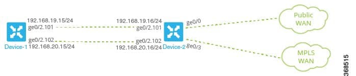
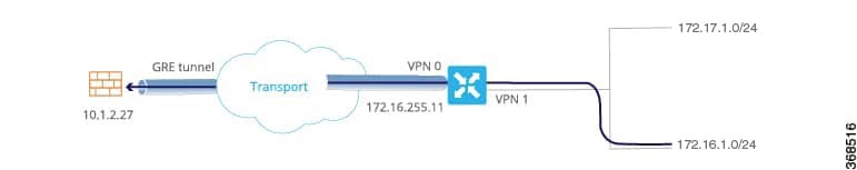
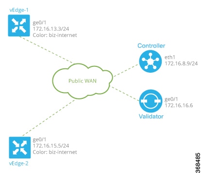
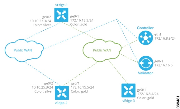
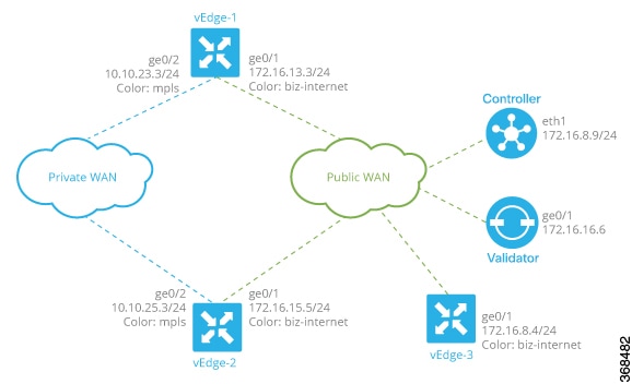

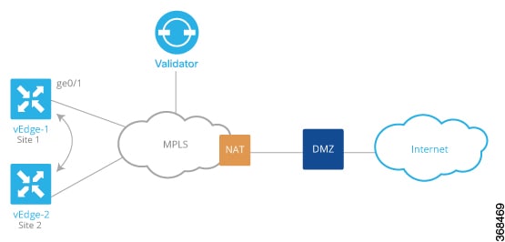
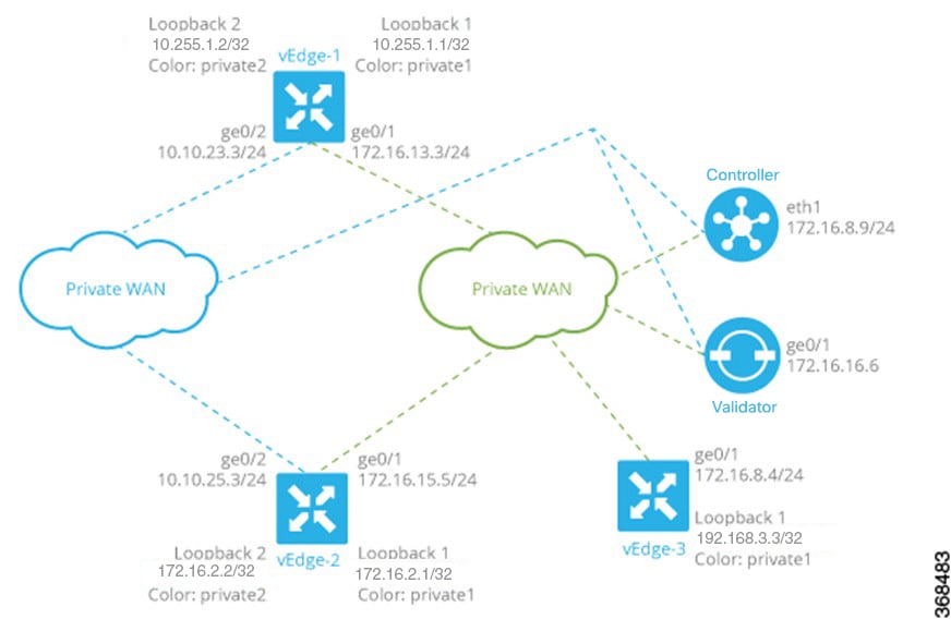
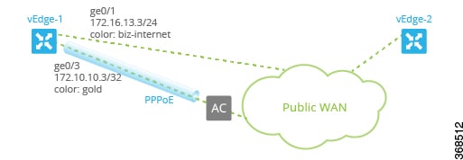
 ), and the default setting or value is shown. To change the default or to enter a value, click the scope drop-down to the
left of the parameter field and select the appropriate option.
), and the default setting or value is shown. To change the default or to enter a value, click the scope drop-down to the
left of the parameter field and select the appropriate option.

 Feedback