Setting Up System Configuration

Default System Configuration on the Cisco ENCS

The diagram below illustrates the default network configuration of Cisco Enterprise NFVIS with the Cisco ENCS.

Figure 1. Default Network Configuration of Cisco Enterprise NFVIS with the Cisco ENCS 5400


Figure 2. Default Network Configuration of Cisco Enterprise NFVIS with the Cisco ENCS 5100
  • LAN ports—Eight physical Gigabit Ethernet ports for inbound and outbound traffic.

  • WAN port—You can use one of the dual media Ethernet ports (wan-br and wan2-br) for DHCP connection.

  • Bridges—They form a Layer 2 domain between virtual network interface controllers (vNICs) of VMs. A vNIC is used by a virtual machine to provide virtual network interfaces by defining a range of MAC addresses. The default management IP address (192.168.1.1) for the NFVIS host is configured on the management port. Multiple VMs can use the same LAN port for local connectivity.

  • Network—It is a segment Layer 2 bridge domain where only the specific VLAN traffic is allowed.

  • Reserved VLANs in the LAN network on the ENCS 5400 platform—The VLAN range 2350-2449 is reserved for internal use and should not be used on the external switch ports and for virtual machines in the LAN ports". Note that this limitation doesn't apply to the WAN ports.

  • Internal 192.168.10.00/24 and 192.168.50.0/24 networks—The IP subnet 192.168.10.0/24 and 192.168.50.0/24 are used for the ENCS-5400 internal networks. A user should not use this IP subnet on the NFVIS management network. In the future NFVIS releases, this internal subnet will be isolated so that users can use this for NFVIS management.


Note


The following networks and bridges are automatically configured. You can configure more as required.

  • A LAN network (lan-net) and a LAN bridge (lan-br)

  • A WAN network (wan-net) and a WAN bridge (wan-br)

wan2-net and wan2-br are the default configurations for ENCS 5400 and ENCS 5100.


The default networks and bridges cannot be deleted.

Default System Configuration on the Cisco UCS C220 M4 Server and Cisco CSP 2100

Configuring the networks in Cisco Enterprise NFVIS allows inbound and outbound traffic and VMs to be service chained. The following diagram illustrates the default network configuration:

Figure 3. Default Network Configuration with Cisco UCS C220 M4 and Cisco CSP 2100


The following networks and bridges are created by default, and cannot be deleted. You can configure more as required.

  • A LAN network (lan-net) and a LAN bridge (lan-br)—The default static management IP address (192.168.1.1) for the NFVIS host is configured on the LAN bridge. One of the ports for inbound and outbound traffic are associated with the LAN bridge. Any LAN port can be used to access the default static IP address. By default, the hostname is set to "nfvis".

  • A WAN network (wan-net) and a WAN bridge (wan-br)—This is created with the "eth0" port, and is configured to enable the DHCP connection.

By default, the first port on the device is associated with the WAN bridge. One of the other ports on the device are associated with the LAN bridge.

For more details about the initial setup, see the Installing the Server chapter in the Cisco UCS C220 M4 Server Installation and Service Guide or Cisco Cloud Services Platform 2100 Hardware Installation Guide.

Default System Configuration on the Cisco UCS E-Series Servers

Figure 4. Default Network Configuration with a Cisco UCS E-Series Server


The following networks and bridges are created by default, and cannot be deleted. You can configure more as required.

  • A LAN network (lan-net) and a LAN bridge (lan-br)—The default static management IP address (192.168.1.1) for the NFVIS host is configured on the LAN bridge. All other ports for inbound and outbound traffic are associated with the LAN bridge. By default, the hostname is set to "nfvis".
  • A WAN network (wan-net) and a WAN bridge (wan-br)— The physical WAN ports are on the Cisco ISR module. They are not externally available on the Cisco UCS E server. The WAN traffic comes from the ISR WAN ports, and goes through the backplane to the Cisco UCS-E server. The backplane has one internal WAN interface (GE0) to establish connection with the Cisco UCS-E server. By default, the "GE0" interface is enabled for the DHCP connection.

For more details on the initial setup, see the Getting Started Guide for Cisco UCS E-Series Servers and the Cisco UCS E-Series Network Compute Engine.

Accessing NFVIS

For initial login, use admin as the default user name, and Admin123# as the default password. Immediately after the initial login, the system prompts you to change the default password. You must set a strong password as per the on-screen instructions to proceed with the application. All other operations are blocked until default password is changed. API returns 401 unauthorized error if the default password is not reset.

If wan-br or wan2-br have not obtained IP addresses through DHCP, the zero touch deployment is terminated. To manually apply the IP configurations answer 'y' and the system proceeds with DHCP assignment on wan-br until the configurations are changed. For DHCP assignment to continue to request IP address for PnP flow on both WAN interfaces answer 'n'.

You must adhere to the following rules to create a strong password:

  • Must contain at least one upper case and one lower case letter.

  • Must contain at least one number and one special character (# _ - * ?).

  • Must contain seven characters or greater. Length should be between 7 and 128 characters.

You can change the default password in three ways:

  • Using the Cisco Enterprise NFVIS portal.

  • Using the CLI (When you first log into Cisco Enterprise NFVIS through SSH, the system will prompt you to change the password).

  • Using PnP (for details, see the Cisco Network Plug-n-Play Support).

  • Using console (After the initial login using the default password, you are prompted to change the default password).

    
    NFVIS Version: 3.10.0-9
    
    Copyright (c) 2015-2018 by Cisco Systems, Inc.
    Cisco, Cisco Systems, and Cisco Systems logo are registered trademarks of Cisco
    Systems, Inc. and/or its affiliates in the U.S. and certain other countries.
    
    The copyrights to certain works contained in this software are owned by other
    third parties and used and distributed under third party license agreements.
    Certain components of this software are licensed under the GNU GPL 2.0, GPL 3.0,
    LGPL 2.1, LGPL 3.0 and AGPL 3.0.
    
    nfvis login: console (automatic login)
    
    login:
    login:
    login:
    login:
    login: admin
    
    Cisco Network Function Virtualization Infrastructure Software (NFVIS)
    
    NFVIS Version: 3.10.0-9
    
    Copyright (c) 2015-2018 by Cisco Systems, Inc.
    Cisco, Cisco Systems, and Cisco Systems logo are registered trademarks of Cisco
    Systems, Inc. and/or its affiliates in the U.S. and certain other countries.
    
    The copyrights to certain works contained in this software are owned by other
    third parties and used and distributed under third party license agreements.
    Certain components of this software are licensed under the GNU GPL 2.0, GPL 3.0,
    LGPL 2.1, LGPL 3.0 and AGPL 3.0.
    
    admin@localhost's password:
    
    admin connected from ::1 using ssh on nfvis
    nfvis# show version
    
    NFVIS Version: 3.12.3
    
    Copyright (c) 2015-2020 by Cisco Systems, Inc.
    Cisco, Cisco Systems, and Cisco Systems logo are registered trademarks of Cisco
    Systems, Inc. and/or its affiliates in the U.S. and certain other countries.
    
    The copyrights to certain works contained in this software are owned by other
    third parties and used and distributed under third party license agreements.
    Certain components of this software are licensed under the GNU GPL 2.0, GPL 3.0,
    LGPL 2.1, LGPL 3.0 and AGPL 3.0.
    
    login: admin
    NFVIS service is OK
    Warning: Permanently added 'localhost' (RSA) to the list of known hosts.
    admin@localhost's password:
    
    
    Cisco Network Function Virtualization Infrastructure Software (NFVIS)
    
    NFVIS Version: 3.12.3-RC8
    
    Copyright (c) 2015-2020 by Cisco Systems, Inc.
    Cisco, Cisco Systems, and Cisco Systems logo are registered trademarks of Cisco
    Systems, Inc. and/or its affiliates in the U.S. and certain other countries.
    
    The copyrights to certain works contained in this software are owned by other
    third parties and used and distributed under third party license agreements.
    Certain components of this software are licensed under the GNU GPL 2.0, GPL 3.0,
    LGPL 2.1, LGPL 3.0 and AGPL 3.0.
    
    
    admin connected from ::1 using ssh on nfvis
    admin logged with default credentials
    Setting admin password will disable zero touch deployment behaviors.
    Do you wish to proceed? [y or n]y
    Please provide a password which satisfies the following criteria:
            1.At least one lowercase character
            2.At least one uppercase character
            3.At least one number
            4.At least one special character from # _ - * ?
            5.Length should be between 7 and 128 characters
    Please reset the password :
    Please reenter the password :
    
    
     Resetting admin password
    
    
    New admin password is set
    
    nfvis#
    System message at 2020-01-08 03:10:10...
    Commit performed by system via system using system.
    nfvis#
    

Note


To commit the target configuration to the active (running) configuration, use the commit command in any configuration mode. Changes made during a configuration session are inactive until the commit command is entered. By default, the commit operation is pseudo-atomic, meaning that all changes must succeed for the entire commit operation to succeed.


Connect to the System

Using IPv4

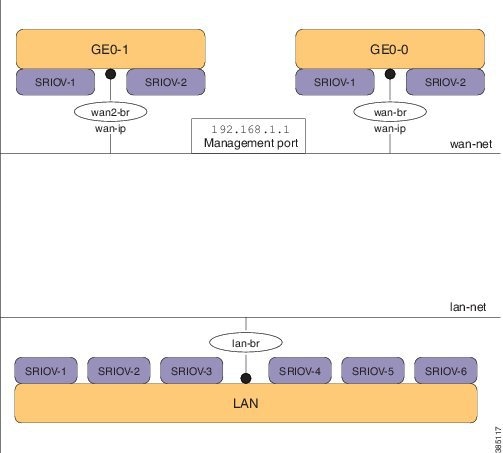
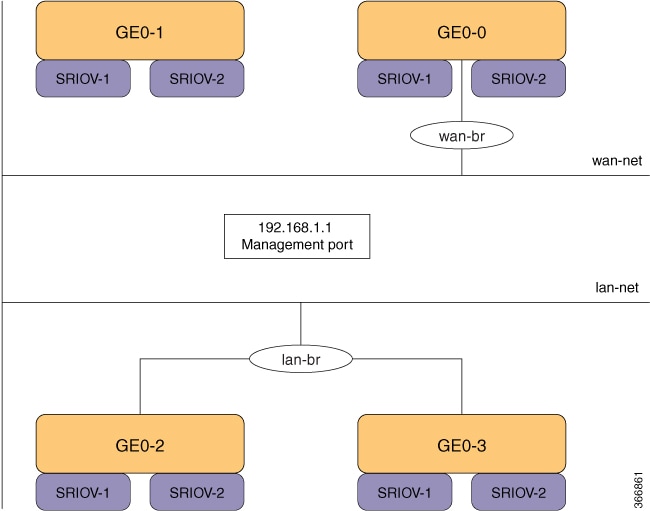
The three interfaces that connect the user to the system are the WAN and WAN2 interfaces and the management interface. By default, the WAN interface has DHCP configuration and the management interface is configured with a static IP address of 192.168.1.1. If the system has a DHCP server connected to the WAN interface, the WAN interface is assigned an IP address from this server. You can use this IP address to connect to the system.

You can connect to the server locally (with an Ethernet cable) using the static management IP address. However, to be able to use a static IP address to remotely connect to a server, the default gateway needs to be configured first.

You can connect to the system in the following ways:

  • Using the local portal—After the initial login, you are prompted to change the default password.

  • Using the KVM console—After the initial login using the default password, you are prompted to change the default password.

  • Using PnP—After the initial provisioning through PnP, the configuration file pushed by the PNP server must include the new password for the default user (admin).

Using IPv6

IPv6 can be configured in static, DHCP stateful and Stateless Autoconfiguration (SLAAC) mode. By default, DHCP IPv6 stateful is configured on the WAN interface. If DHCP stateful is not enabled on the network, the router advertisement (RA) flag decides which state the network stays in. If the RA shows the Managed (M) flag, then the network stays in DHCP mode, even if there is no DHCP server in the network. If the RA shows the Other (O) flag, then the network switches from DHCP server to SLAAC mode.

SLAAC provides IPv6 address and default gateway. Stateless DHCP is enabled in the SLAAC mode. If the server has DNS and domain configured, then SLAAC also provides those values via stateless DHCP.

Perform Static Configuration without DHCP


Note


Starting from NFVIS 3.10.1 release, for ENCS 5400 and ENCS 5100, wan2-br obtains an IP address from DHCP. To configure default gateway, first use the no bridges bridge wan2-br dhcp command.


If you want to disable DHCP and use static configuration, you need to perform the initial configuration by setting the WAN IP address and/or management IP address, and the default gateway. You can also configure a static IP on a created bridge.

To perform initial configuration on the system without using DHCP:


configure terminal
system settings mgmt ip address 192.168.1.2 255.255.255.0 
bridges bridge wan-br ip address 209.165.201.22 255.255.255.0
system settings default-gw 209.165.201.1
commit

Note


When an interface is configured with a static IP address, DHCP is automatically disabled on that interface.


Now you can either use the management IP or WAN IP to access the portal.

To configure static IPv6 on the WAN interface:


configure terminal
system settings mgmt ipv6 address 2001:DB8:1:1::72/64 
bridges bridge wan-br ipv6 address 2001:DB8:1:1::75/64
system settings default-gw-ipv6 2001:DB8:1:1::76
commit

Note


When an interface is configured with a static IPv6 address, DHCP IPv6 is automatically disabled on that interface. There are three options for IPv6 - static, DHCP and SLAAC, out of which only one can be enabled at a time.

Secure overlay is not supported when WAN interface is configured with IPv6.


To configure DHCP on the WAN interface:


configure terminal
no system settings default-gw
system settings wan dhcp
commit
exit
hostaction wan-dhcp-renew

Note


Starting from NFVIS 3.10.1, you can configure DHCP IPv6 on any bridge. You can only have one DHCP IPv6 bridge or management interface active at a time. You cannot have DHCP IPv6 and default IPv6 gateway or SLAAC IPv6 configured at the same time.


To configure DHCP IPv6 on the WAN interface:


configure terminal
no system settings default-gw-ipv6
system settings wan dhcp-ipv6
commit
exit
hostaction wan-dhcp-renew

Verify Initial Configuration

Use the show system settings-native command to verify initial configuration. Use show bridge-settings and show bridge-settings bridge_name commands to verify the configuration for any bridge on the system.

Here is an extract from the output of the show system settings-native command when both WAN and management interfaces have a static configuration:


system settings-native mgmt ip-info interface lan-br
system settings-native mgmt ip-info ipv4_address 192.168.1.2
system settings-native mgmt ip-info netmask 255.255.255.0
!
!
!
system settings-native mgmt dhcp disabled
system settings-native wan ip-info interface wan-br
system settings-native wan ip-info ipv4_address 209.165.201.22 
system settings-native wan ip-info netmask 255.255.255.0
!
!
!
system settings-native wan dhcp disabled
!
!
system settings-native gateway ipv4_address 209.165.201.1
system settings-native gateway interface wan-br


Here is an extract from the output of the show system settings-native command when the management interface has a DHCP configuration and the WAN interface has a static configuration:


system settings-native mgmt ip-info interface MGMT
system settings-native mgmt ip-info ipv4_address 192.168.1.2
system settings-native mgmt ip-info netmask 255.255.255.0
!
!
!
system settings-native mgmt dhcp enabled
system settings-native wan ip-info interface wan-br
system settings-native wan ip-info ipv4_address 209.165.201.22
system settings-native wan ip-info netmask 255.255.255.0
!
!
!
system settings-native wan dhcp disabled


Here is an extract from the output of the show system settings-native command when the WAN interface has a DHCP configuration and the management interface has a static configuration:


system settings-native mgmt ip-info interface lan-br
system settings-native mgmt ip-info ipv4_address 209.165.201.2 
system settings-native mgmt ip-info netmask 255.255.255.0
!
!
!
system settings-native mgmt dhcp disabled
system settings-native wan ip-info interface wan-br
system settings-native wan ip-info ipv4_address 209.165.201.22
system settings-native wan ip-info netmask 255.255.255.0
!
!
!
system settings-native wan dhcp enabled


Configuring VLAN for NFVIS Management Traffic

A VLAN creates independent logical networks within a physical network. VLAN tagging is the practice of inserting a VLAN ID into a packet header in order to identify which VLAN the packet belongs to.

You can configure a VLAN tag on the WAN bridge (wan-br) interface to isolate Cisco Enterprise NFVIS management traffic from VM traffic. You can also configure VLAN on any bridge on the system (wan2-br for ENCS5400 or ENCS 5100, and user-br for all systems)

By default, WAN bridges and LAN bridges are in trunk mode and allows all VLANs. When you configure native VLAN, you must also configure all the allowed VLANs at the same time. The native VLAN becomes the only allowed VLAN if you do not configure all the VLANs. If you want a network that allows only one VLAN, then create another network on top of wan-net and lan-net and make it access network.


Note


You cannot have the same VLAN configured for the NFVIS management and VM traffc.


For more details on the VLAN configuration, see the Understanding and Configuring VLANs module in the Catalyst 4500 Series Switch Cisco IOS Software Configuration Guide.

Configuring System Routes

In addition to the default routes in the system, you can configure additional system routes. This configuration is specifically useful when certain destinations are not reachable through the default routes.

While you can create a route just by providing the destination and prefix length, a valid route requires that you specify either a device or a gateway or both.

To configure additional system routes:


configure terminal
system routes route  209.165.201.1 dev lan-br
commit

Verifying the System Routes Configuration

To verify the system routes configuration, use the show system routes command as shown below:


nfvis# show system routes
DESTINATION 	PREFIXLEN 	STATUS
----------------------------------
209.165.201.1 	12 -
209.165.201.2 	12 -
209.165.201.3 	24 -

System Routes APIs and Commands

System Routes APIs

System Routes Commands

  • /api/config/system/routes

  • /api/config/system/routes/route/<host

    destination,netmask>

  • system routes route

  • show system routes

User Roles and Authentication

Role based access enables the administrator to manage different levles of access to the system's compute, storage, database, and application services. It uses the access control concepts such as users, groups, and rules, which you can apply to individual API calls. You can also keep a log of all user activities.

Table 1. Supported User Roles and Privileges

User Role

Privilege

Administrators

Owns everything, can perform all tasks including changing of user roles, but cannot delete basic infrastructure. Admin's role cannot be changed; it is always "administrators".

Operators

Start and stop a VM, and view all information

Auditors

Read-only permission

Rules for User Passwords

The user passwords must meet the following requirements:

  • Must have at least seven characters length or the minimum required length configured by the admin user.

  • Must not have more than 128 characters.

  • Must contain a digit.

  • Must contain one of the following special characters: hash (#), underscore (_), hyphen (-), asterisk (*), and question mark (?).

  • Must contain an uppercase character and a lowercase character.

  • Must not be same as last five passwords.

Creating Users and Assigning Roles

The administrator can create users and define user roles as required. You can assign a user to a particular user group. For example, the user "test1" can be added to the user group "administrators".


Note


All user groups are created by the system. You cannot create or modify a user group.


To create a user:


configure terminal
rbac authentication users create-user name test1 password Test1_pass role administrators
commit

To delete a user:


configure terminal
rbac authentication users delete-user name test1
commit

Note


To change the password, use the rbac authentication users user change-password command in global configuartion mode. To change the user role, use the rbac authentication users user change-role command in global configuration mode.


User Management APIs and Commands

User Management APIs

User Management Commands

  • /api/config/rbac/authentication/users

  • /api/operations/rbac/authentication/users

    /user/<user-name>/change-password

  • /api/operations/rbac/authentication/users/user

    /oper/change-role

  • /api/config/rbac/authentication/users/user?deep

  • rbac authentication users

  • rbac authentication users user change-password

  • rbac authentication users user change-role

Configuring Minimum Length for Passwords

The admin user can configure the minimum length required for passwords of all users. The minimum length must be between 7 to 128 characters. By default, the minimum length required for passwords is set to 7 characters.


configure terminal
rbac authentication min-pwd-length 10
commit

Minimum Password Length APIs and Commands

APIs

Commands

/api/config/rbac/authentication/

rbac authentication min-pwd-length

Configuring Password Lifetime

The admin user can configure minimum and maximum lifetime values for passwords of all users and enforce a rule to check these values. The default minimum lifetime value is set to 1 day and the default maximum lifetime value is set to 60 days.

When a minimum lifetime value is configured, the user cannot change the password until the specified number of days have passed. Similarly, when a maximum lifetime value is configured, a user must change the password before the specified number of days pass. If a user does not change the password and the specified number of days have passed, a notification is sent to the user.


Note


The minimum and maximum lifetime values and the rule to check for these values are not applied to the admin user.


configure terminal
rbac authentication password-lifetime enforce true min-days 2 max-days 30
commit

Password Lifetime APIs and Commands

APIs

Commands

/api/config/rbac/authentication/password-lifetime/

rbac authentication password-lifetime

Deactivating Inactive User Accounts

The admin user can configure the number of days after which an unused user account is marked as inactive and enforce a rule to check the configured inactivity period. When marked as inactive, the user cannot login to the system. To allow the user to login to the system, the admin user can activate the user account by using the rbac authentication users user username activate command.


Note


The inactivity period and the rule to check the inactivity period are not applied to the admin user.


configure terminal
rbac authentication account-inactivity enforce true inactivity-days 2
commit

Deactivate Inactive User Accounts APIs and Commands

APIs

Commands

/api/config/rbac/authentication/account-inactivity/

rbac authentication account-inactivity

Activating an Inactive User Account

The admin user can activate the account of an inactive user.


configure terminal
rbac authentication users user guest_user activate
commit

Activate Inactive User Account APIs and Commands

APIs

Commands

/api/operations/rbac/authentication/users/user/username/activate

rbac authentication users user activate

Certification

Generate Sign-Request


nfvis(config)# system certificate signing-request ?

Possible completions:

  common-name             country-code  

  locality                organization  

  organization-unit-name  state 

The .csr file will be saved in /data/intdatastore/download/nfvis.csr

Use the scp command to download the file.

Install CA Sign Certificate

After CA sign in, the user needs to use the scp command to upload the file into nfvis.


nfvis(config)# system certificate install-cert path file:///<full path of the file>

The path needs to start with "file://"

Switch Certificate


nfvis(config)# system certificate use-cert cert-type ca-signed

nginx process restarts after the switch.

The users cannot access the log files. The log files are added to all the user actions and the user can download and view some of the logs from portal. A notification is generated when the log files reach 75% capacity.

Secure Copy Command

The secure copy (scp) command allows only the admin user to secure copy a file from the Cisco NFVIS to an external system or from an external system to Cisco NFVIS. The scp command is:

scp source destination


Note


For detailed information about how to use the scp command to copy to or from supported locations, see the scp section in Cisco Enterprise Network Function Virtualization Infrastructure Software Command Reference.


Examples

The following example copies the sample.txt file from intdatastore to an external system.

nfvis# scp intdatastore:sample.txt user@203.0.113.2:/Users/user/Desktop/sample.txt

The following example copies the test.txt file from an external system to intdatastore.

nfvis# scp user@203.0.113.2:/Users/user/Desktop/test.txt intdatastore:test_file.txt

The following example copies the test.txt file from an external system to USB.

nfvis# scp user@203.0.113.2:/user/Desktop/my_test.txt usb:usb1/test.txt

The following example copies the sample.txt file to an NFS location.

nfvis# scp user@203.0.113.2:/user/Desktop/sample.txt nfs:nfs_test/sample.txt

The following example copies the sample.txt file from an external system with IPv6 address.

nfvis# scp user@[2001:DB8:0:ABCD::1]:/user/Desktop/sample.txt intdatastore:sample.txt

The following example copies the nfvis_scp.log file to an external system.

nfvis# scp logs:nfvis_scp.log user@203.0.113.2:/Users/user/Desktop/copied_nfvis_scp.log

Configuring the IP Receive ACL

To filter out unwanted traffic, you can configure ip-receive-acl to block or allow certain traffic based on the IP address and service ports.

To configure the source network for Access Control List (ACL) access:


configure terminal
system settings ip-receive-acl 198.0.2.0/24
action accept priority 10
commit

Verifying the Trusted IP Connection

Use the show running-config system settings ip-receive-acl command to display the configured source network for ACL access to the management interface


nfvis# show running-config system settings ip-receive-acl 
system settings ip-receive-acl 198.51.100.11/24
service
[ ssh https scpd]
action accept
priority 100

Port 22222 and Management Interface ACL

Port 22222 is used for SCP server and is closed by default on an NFVIS system. You cannot SCP a file into NFVIS from an external server. If you need to SCP file from an external server, you must first open the port.

To open port 22222:


config terminal
system settings ip-receive-acl address/mask_len service scpd priority 2 action accept
commit

The Access Control List (ACL) is identify by address. If this ACL is removed, all ACLs sharing the same address are also removed. Ensure that you configure the ACLs that share the same address once again.


Note


From 3.8.1 release, only users with administrator priviledges can use the SCP command on port 22222 to upload or download only from restricted folders like /data/intdatastore/. For more information, see Host System Operations.


Caution


SCP command cannot be used to copy files from one NFVIS device to another NFVIS device.


Use the show running-config system settings ip-receive-acl command to verify the interface configuration:


nfvis# show running-config system settings ip-receive-acl

system settings ip-receive-acl 10.156.0.0/16

 service  [ ssh https scpd ]

 action   accept

 priority 100

!

Configuring Your Banner and Message of the Day

Cisco Enterprise NFVIS supports two types of banners: system-defined and user-defined banners. You cannot edit or delete the system-defined banner, which provides copyright information about the application. Banners are displayed on the login page of the portal.

You can post messages using the Message of the Day option. The message is displayed on the portal's home page when you log into the portal.

To configure your banner and message:


configure terminal
banner-motd banner "This is a banner" motd "This is the message of the day"
commit

Note


Currently, you can create banners and messages in English only. You can view the system-defined banner using the show banner-motd command. This command does not display the user-defined banner or message.


Banner and Message APIs and Commands

Banner and Message APIs

Banner and Message Commands

  • /api/config/banner-motd

  • /api/operational/banner-motd

  • banner-motd

  • show banner-motd

Setting the System Time Manually or With NTP

You can configure the Cisco Enterprise NFVIS system time manually or synchronise with an external time server using Network Time Protocol (NTP).

To set the system time manually:


configure terminal
system set-manual-time 2017-01-01T00:00:00
commit

Note


NTP is automatically disabled when the time clock is set manually.


To set the system time using NTP IPv4:


configure terminal
system time  ntp preferred_server 209.165.201.20 backup_server 1.ntp.esl.cisco.com
commit

To set the system time using NTP IPv6:


configure terminal
system time  ntp-ipv6 2001:420:30d:201:ffff:ffff:fff4:35
commit

Verifying the System Time Configuration

To verify all system time configuration details, use the show system time command in privileged EXEC mode as shown below:


nfvis# show system time

system time current-time 2017-01-01T17:35:39+00:00

system time current-timezone "UTC (UTC, +0000)"

REMOTE               REFID  	ST   	T         WHEN       POLL       REACH         DELAY         OFFSET        JITTER    

=================================================================================================================================================

*calo-timeserver     .GPS.   	1          u           4  	64           1         69.423         2749736        0.000     

* sys.peer and synced, o pps.peer, # selected, + candidate,

- outlyer, . excess, x falseticker, space reject

If the NTP server is invalid, it will not be displayed in the table. Also, when an NTP server is queried, if a response is not received before the timeout, the NTP server is not displayed in the table.

System Time APIs and Commands

APIs

Commands

  • /api/operations/system/set-manual-time

  • /api/config/system/time/ntp/preferred_server

  • /api/config/system/time/ntp/backup_server

  • /api/config/system/time/timezone

  • /api/operational/system/time?deep

  • system time

  • show system time

  • system set-manual-time

Enable or Disable Access to NFVIS Portal

The Cisco Enterprise NFVIS portal access is enabled by default. You can disable the access if required.

To disable the portal access:


configure terminal
system portal access disabled 
commit

Note


You can enable the portal access using the enabled keyword with the system portal access configuration.


Verifying the Portal Access

Use the show system portal status command to verify the portal access status as shown below:


nfvis# show system portal status
system portal status "access disabled"

Portal Access APIs and Commands

Portal Access APIs

Portal Access Commands

  • /api/config/system/portal

  • /api/operational/system/portal/status

  • system portal access

  • show system portal status

Configuring System Logs

NFVIS generates log files for troubleshooting issues. The configuration log and the operational log are the two main system log files. The configuration log has information related to configurations and actions performed on the system such as creation of networks. The operational log has information related to system operation such as statistics collection and monitoring.

Log entries can be one of the following types:

Log Level

Purpose

DEBUG

Information, typically of interest only when diagnosing problems.

INFO

Confirmation that things are working as expected.

WARNING

An indication that something unexpected happened, or indicative of some problem in the near future (for example, ‘disk space low’). The software application is still working as expected.

ERROR

Due to a serious problem, the software application is not able to perform some function.

CRITICAL

A serious error, indicating that the program itself may not be able to continue running.

By default, the configuration log has a log-level of INFO. All logs of type INFO, WARNING, ERROR and CRITICAL are logged.

By default, the operational log has a log-level of WARNING. All logs of type WARNING, ERROR and CRITICAL are logged.

The log-level for these log files can be changed using the system set-log command:


system set-log level error logtype configuration

The change to the log level is not persistant across a reboot. After a reboot, the default log levels are used.

The current log files are kept in the /var/log directory in the system:

  • show log - To display the list of available log files

  • show log {filename} - To display the contents of a specific log file

Log Rotation

There is a size limit for the log files, under /var/log/ directory. When the log files reach the size limit, the location of logs is rotated to another place. The space limit for the total size of all rotated log files is 2 GB. The older log files are dropped automatically on reaching the space limit. You can also execute a command to trigger the log rotation procedure. The log files are monitored periordically and if a log file gets too big, it is rotated to another place.

There is a size limit for the log files stored in the /var/log directory. The size of the log files is monitored periodically every fifteen minutes and if a log file gets too big, it is rotated to the /data/intdatastore/logs directory. The space limit for the total size of all the rotated log files is 2 GB. The older log files are dropped automatically on reaching the space limit. You can also execute the logrotate command to trigger the log rotation procedure.


nfvis# logrotate

Verifying the System Log Configuration

To verify the system log configuration, use the show system logging-level command as shown below:


nfvis# show system logging-level
system logging-level configuration error
system logging-level operational warning

System Log APIs and Commands

System Log APIs

System Log Commands

  • /api/operations/system/set-log

  • /api/operational/system/logging-level

  • system set-log logtype [all/configuration/operational] level [critical/debug/error/info/warning]

  • show system logging-level

Network File System Support

Network File System (NFS) is an application where you can view, store, and update the files on a remote device. NFS allows you to mount all or a part of a file system on a server. NFS uses Remote Procedure Calls (RPC) to route requests between the users and servers.

Mount and Unmount NFS

The following example shows how to mount NFS:


configure terminal
system storage nfs_storage
nfs
100
10.29.173.131
/export/vm/amol
commit

To unmount NFS use the no system storage nfs_storage command.

Image Registration on NFS

Images in tar.gz, ISO and qcow2 formats, remote images and images on mounted NFS can be registered on NFS.

To register tar.gz images on NFS:


configure terminal
vm_lifecycle images image myas10 src file:///data/mount/nfs_storage/repository/asav961.tar.gz
properties property placement value nfs_storage
commit

Similar configuration can be used for the various images formats.

To unregister an image from NFS use no vm_lifecycle images command.

Deploy VM on NFS

To deploy a VM on NFS, under deployment vm group, use the placement type zone_host host nfs_storage command.

Secure Boot of host


Note


This feature is available only for NFVIS 3.9.1 release fresh install and supported only on ENCS 5400. Upgrade BIOS to version 2.6 for this feature.


The secure boot feature prevents malicious software applications and unauthorized operating systems from loading into the system during the system start up process. If secure boot feature is enabled, only the authorized software applications boots up from the device. Each device has keys that allow software with the correct signature to boot up on the device.

This feature ensures that the software applications that boot up on the device are certified by Cisco. The NFVIS 3.9.1 image is signed with Cisco key. If secure boot is enabled the signature is verified during the device boot up. If the verification fails, the image does not boot up.

Secure boot is disabled by default and to enable it you must change firmware configurations from CIMC. Secure boot needs to boot from a separate UEFI partition.

To enable secure boot:

  1. Access CIMC and use show bios detail command to view the BIOS version.

    
    ENCS# scope bios
    ENCS/bios # show detail
    BIOS:
        BIOS Version: " ENCS54_2.6 (Build Date: 07/12/2018)"
        Boot Order: EFI
        FW Update/Recovery Status: Done, OK
        Active BIOS on next reboot: main
        UEFI Secure Boot: disabled
    ENCS/bios # 
    
  2. Enable secure boot of host.

    
    ENCS/bios # set secure-boot enable
    Setting Value : enable
    Commit Pending.
    ENCS/bios *# commit
    ENCS/bios # show detail
    BIOS:
        BIOS Version: "ENCS54_2.6 (Build Date: 07/12/2018)"
        Boot Order: EFI
        FW Update/Recovery Status: None, OK
        Active BIOS on next reboot: main
        UEFI Secure Boot: enabled
    ENCS/bios #

Legacy boot, UEFI boot and UEFI secure boot are the three boot modes. Secure boot can only be used on a disk that has UEFI partition.

You can configure boot order from CIMC command or portal or from BIOS setup menu. You can only configure legacy boot order with CIMC . By default, BootOrderRules are set to Strict , so the boot order follows the CIMC configuration. Since CIMC cannot be used to configure UEFI boot order, to enable secure boot change the BootOrderRules setting to Loose .

If BootOrderRules is set to Loose , the boot order follows the BIOS setup menu. When an operating system is installed in secure boot mode, the new UEFI boot option for the OS automatically appears at the top of the BIOS menu boot order list, to boot the installed operating system.

To set BootOrderRules to Loose :


ENCS/bios # scope advanced 
ENCS/bios/advanced # set BootOrderRules Loose
ENCS/bios/advanced *# commit
Changes to BIOS set-up parameters will require a reboot.
Do you want to reboot the system?[y|N]y

CIMC Access Control

NFVIS administrators have authoritative control control over ENCS 5400 devices. This includes capability to change the IP address used to reach the CIMC and modifying the CIMC and BIOS passwords.

CIMC Access using NFVIS


Note


CIMC access using NFVIS is supported only on ENCS 5400.

When CIMC access is enabled on NFVIS, ISRv can gain access to the host CIMC and internal switch management console. You must have authorization from Cisco Interactive Debug (CID) to access both consoles.


To access CIMC using NFVIS WAN or management interface IP address, use the system settings cimc-access enable command. Once you configure CIMC access on NFVIS, the stand alone CIMC access using CIMC IP address is disabled and you will be able to access CIMC using NFVIS management interface IP address. The configurations remain on the device even after the device reboot.

When the CIMC access is configured, it enables a few ports to access services like SSH, SNMP, HTTP and HTTPs into the CIMC.

The following port numbers are being used for forwarding services to CIMC:

  • 20226 for SNMP

  • 20227 for SSH

  • 20228 for HTTP

  • 20229 for HTTPS

If you are unable to access CIMC using NFVIS, check the show log nfvis_config.log file.

Use system settings cimc-access disable to disable this feature.

BIOS-CIMC Update

For releases 3.8.1 and later, if the BIOS or CIMC versions on Cisco ENCS 5400 routers are lower than the image version in the NFVIS ISO or upgrade package, the BIOS and CIMC versions on the routers are automatically upgraded to the version of the bundled image during NFVIS upgrade or installation. The CPU microcode is also upgraded as part of this upgrade or installation. Note that the upgrade process takes longer than in previous releases and the process cannot be stopped midway.

For Cisco ENCS 5100 routers, BIOS is automatically upgraded to the new version, but the server needs to be rebooted manually for the upgrade to show.

BIOS and CIMC Password

Table 2. Feature History

Feature Name

Release Information

Description

BIOS and CIMC password

NFVIS 4.2.1

New password restrictions and security measures are added for CIMC and BIOS.

To change the BIOS and CIMC password for ENCS 5400, use hostaction change-bios-password newpassword or hostaction change-cimc-password newpassword commands. The change in the password will take effect immediately after the commands are executed.


Note


New password restrictions added for CIMC and BIOS in NFVIS 4.2.1 release.


You must adhere to the following rules to create a strong password for CIMC:

  • Must contain at least one upper case and one lower case letter.

  • Must contain at least one number and one special character from #, @ or _.

  • Length should be between 8 and 20 characters.

  • Should not contain the following string (case sensitive): admin

You must adhere to the following rules to create a strong password for BIOS:

  • The first letter cannot be #.

  • Must contain at least one upper case and one lower case letter.

  • Must contain at least one number and one special character from #, @ or _.

  • Length should be between 8 and 20 characters.

  • Should not contain the following string (case sensitive): bios

Starting from BIOS version 2.11 and CIMC 3.2.10, the new BIOS password security measures are:

  • BIOS password can only be set through CIMC XML API or NFVIS. It can no longer be configured in the BIOS setup menu.

  • BIOS password is retained after BIOS updates and it does not have to be reconfigured after a BIOS update.

  • Only an admin password can be set and user-level BIOS password can no longer be set.

BIOS and CIMC Password APIs and Commands

BIOS and CIMC Password APIs

BIOS and CIMC Password Commands

  • /api/operations/hostaction/change-cimc-password

    /api/operations/hostaction/change-bios-password

  • hostaction change-cimc-password

  • hostaction change-bios-password

NFVIS Password Recovery

  1. Load the NFVIS ISO image, using the CIMC KVM console.

  2. Select Troubleshooting from the Boot Selection menu.

  3. Select Rescue a NFVIS Password.

  4. Select Continue.

  5. Press Return to get a shell.

  6. Run the chroot /mnt/sysimage command.

  7. Run the ./nfvis_password_reset command to reset the password to admin.

  8. Confirm the change in password and enter Exit twice.

    Disconnect the NFVIS ISO image in the CIMC KVM console and reboot NFVIS.

  9. Login to NFVIS with the default credentials admin/Admin123#.

    After login to NFVIS, enter a new password at prompt.
  10. Connect to NFVIS with the new password.


Note


You can update and recover NFVIS 3.8.1 and older passwords using NFVIS 3.9.1.


UEFI Secure Boot on ENCS 5400

The Unified Extensible Firmware Interface (UEFI) Secure Boot mode ensures that all EFI drivers and applications, ROMs or operating systems are signed and verified for authenticity and integrity before they are loaded and executed. This feature can be enabled through the GUI or CLI. When you enable UEFI secure boot mode, the boot mode is set to UEFI mode and you cannot modify the configured boot mode until the UEFI boot mode is disabled.


Note


If you enable UEFI secure boot on an unsupported OS, on the next reboot, you cannot boot the device from that particular OS when you try to reboot the next time. If you try to reboot from such unsupported OS, an error is reported and recorded under System Software Events in the GUI. You must disable the UEFI secure boot option using Cisco IMC to be able to boot from the OS that does not support UEFI secure boot.


Enabling UEFI Secure Boot Mode

To enable UEFI secure boot mode:


Server# scope bios
Server /bios # set secure-boot enable
Setting Value : enable
Commit Pending.
Server /bios *# commit

Reboot the server to have your configuration boot mode settings to take effect.

Disabling UEFI Secure Boot Mode

To disable UEFI secure boot mode:


Server# scope bios
Server /bios # set secure-boot disable
Setting Value : enable
Commit Pending.
Server /bios *# commit

Reboot the server to have your configuration boot mode settings to take effect.

To install NFVIS in UEFI mode, map the iso image through vmedia or kvm first, then enable secure boot and change the BIOS set-up parameters.


encs# scope bios
encs /bios # scope advanced
encs /bios/advanced # set BootOpRom UEFI
encs /bios/advanced # set BootOrderRules Loose
encs /bios/advanced *# commit

Reboot the device to start the installation.

To configure the UEFI virtual-mapped image as the first boot option, enter the BIOS menu using F2 key when BIOS boots up. Use direction keys to move UEFI: Cisco CIMC-mapped image or KVM-mapped image to the top of the boot option list. For BIOS v2.10 onwards, you can also configure the UEFI boot order through CIMC GUI or CLI. For more information see, Install Cisco Enterprise NFVIS.


Note


All VNFs and configurations are lost at reboot. Secure boot in UEFI mode works differently from the legacy mode. Therefore, there is no compatibility in between legacy mode and UEFI mode. The previous environment is not kept.


DPDK Support on NFVIS

The Data Plane Development Kit (DPDK) is a set of data plane libraries and network interface controller drivers for fast packet processing.

DPDK Support for NFVIS 3.10.x

DPDK support is enabled only on ENCS 5400 from NFVIS 3.10.1 release. To enable DPDK use system settings dpdk enable command. Once DPDK is enabled it cannot be disabled. You can use factory-default-reset all-except-images-connectivity to disable DPDK.

To enable DPDK support:


configure terminal
system settings dpdk enable
commit

DPDK can be enabled if:

  • No VMs are deployed.

  • There are no other bridges created other than the default bridge which is wan-br, wan2-br or lan-br.

  • The default bridges are not modified.

DPDK mode is enabled on a bridge, if the bridge is created as part of a network or bridge api without any NIC ports. NIC ports can also be added later to the bridge, if no VMs are deployed on the network associated to the bridge. If a NIC port is added to the bridge, the bridge will switch to non-dpdk mode. Once a bridge enters non-dpdk mode, it will not switch back to DPDK mode again. NFVIS supports DPDK for the interface with virtio driver only.


Note


NFVIS 3.10.x release does not support tcpdump packetcapture command on DPDK enabled bridge.


If DPDK is enabled, all VMs deployed will have DPDK and HugePage support. The default hugepage size is 2MB. After DPDK is enabled the system reserves 512 hugepages for Openvswitch operations. Hugepages for VM are allocated dynamically. If the system is not able to allocate HugePages for a newly deployed VM, the VM will boot up in error state. Memory Fragmentation is the main reason why HugePage allocation fails. In this case a reboot can help solve the issue.


Note


DPDK support is only enabled on the bridges without NIC ports.


For a system without Hyper-threading one additional core is reserved by the system and for a system with Hyper-threading two additional logical cores are reserved by the system.

NFVIS does not support changing Hyper-thread option such as disabling after DPDK is enabled with Hyper-thread. The system can be unstable if you change Hyper-thread setting after DPDK is enabled.

DPDK VM Migration for NFVIS 3.11.x

Enhancements to DPDK Support in NFVIS 3.12.x

Service Bridge DPDK Support for New Platforms

Starting from NFVIS 3.12.1 DPDK support is added for service bridges on UCS-C M5, UCS-E M3 and CSP 5000 series. Only the service bridge is supported and the default wan bridge and lan bridge do not support DPDK feature. DPDK is supported on service bridge with or without any pnic. The configuration for service bridge without any pnic is the same as ENCS platform on NFVIS 3.11.1 release, all service bridges will become dpdk-capable after DPDK is enabled. NFVIS system does not require reboot after DPDK is enabled.

DPDK and SR-IOV cannot co-exist on the pnic used for DPDK-capable bridge. The configuration for service bridge with pnic is as followed:

  1. (Optional) If pnic ethX-Y is still attached to lan-br, remove it from lan-br.

    
    configure terminal
    bridges bridge lan-br
    no port ethX-Y
    commit
    
  2. Remove SR-IOV networks associated with ethX-Y (usually ethX-Y-SRIOV-*).

    
    configure terminal
    no networks network ethX-Y-SRIOV-1
    no networks network ethX-Y-SRIOV-2
    ...
    commit
    
  3. Disable ethX-Y SRIOV configuration.

    
    configure terminal
    pnic ethX-Y
    no sriov
    nnumvf 0
    commit
    
  4. Create service bridge with port ethX-Y.

    
    configure terminal
    bridges bridge service-br port ethX-Y
    networks network service-net bridge service-br
    commit
    
  5. Enable system-wide DPDK setting.

    
    configure terminal
    system settings dpdk enable
    commit
    

Note


  • You can also enable DPDK before creating service bridge with port ethX-Y.

  • Except ENCS 5400 platform, all default bridges (lan-br, wan-br, wan-br2) does not enter DPDK-mode after DPDK is enabled system-wide.

  • If you do not remove SR-IOV configuration from pnic ethX-Y, and ethX-Y is a port of service bridge, this service bridge cannot enter DPDK-mode after DPDK is enabled system-wide. If you have to use pnic ethX-Y in DPDK bridge, after removing SR-IOV configuration from ethX-Y, delete old bridge and create new bridge and attach ethX-Y to the new bridge.


Migration for VMs with PNIC associated to DPDK bridge

If DPDK is enabled, all VMs deployed will have DPDK and HugePage support. The default hugepage size is 2MB. After DPDK is enabled, the system will reserve additional 512~2048 contiguous hugepages for DPDK operations. Though hugepages for VM are allocated dynamically, it will cause memory fragmentation and the main reason DPDK enabling process will fail. In this case, a system reboot might help to solve the issue.

If system can find enough hugepages for DPDK process, not only service bridges will enter DPDK-mode, all VMs’ vnic attached to those bridges will be migrated from virtio to dpdk type (dpdkvhostuserclient):


nfvis# support ovs vsctl show | begin service-br
    Bridge service-br
        Port "vnic2"
            Interface "vnic2"
                type: dpdkvhostuserclient
                options: {vhost-server-path="/run/vhostfd/vnic2"}
        Port service-br
            Interface service-br
                type: internal

nfvis# support virsh dumpxml ROUTER | begin interface | until serial
    <interface type='network'>
      <mac address='52:54:00:ae:14:57'/>
      <source network='wan-net'/>
      <target dev='vnic1'/>
      <model type='virtio'/>
      <address type='pci' domain='0x0000' bus='0x00' slot='0x04' function='0x0'/>
    </interface>
    <interface type='vhostuser'>
      <mac address='52:54:00:3d:ee:1a'/>
      <source type='unix' path='/run/vhostfd/vnic2' mode='server'/>
      <target dev='vnic2'/>
      <model type='virtio'/>
      <address type='pci' domain='0x0000' bus='0x00' slot='0x05' function='0x0'/>
    </interface>

DPDK and Factory Reset

The three commonly-used factory reset configurations disable DPDK.

Factory-default-reset configuration

DPDK enabled

Networks kept

Deployment deleted

Registered image deleted

all

No

No

Yes

Yes

all-except-images

No

No

Yes

No

all-except-images -connectivity

No

Yes

Yes

No

Frequently Seen Failures

  • Error when DPDK is enabled.

    • When enabling DPDK, lack of system memory results in an error. Ensure that you have 4 GB contiguous HugePages to enable DPDK. You can also reboot the system.

    • DPDK requires one physical core from each socket. A multi-sockets system (like UCS-C or CSP) can encounter deployments that occupy all cores on one socket and DPDK can fail to enable. Power-off some VM (resource-locking VMs likes ISRv/ASAv/vWAAS) and enable VM after DPDK is enabled successfully.

  • If the system is not able to allocate HugePages for a newly deployed VM, the VM will boot up in error state.

Import and Export NFVIS VM

Starting from NFVIS 3.10.1 release, you can backup or export (vmExportAction) and restore or import (vmImportAction) VMs. To backup or restore the whole NFVIS system, refer Backup and Restore NFVIS and VM Configurations.

VM Export and Import Limitations

  • The imported VM cannot change datastore.

  • The original registered image must exist.

  • The OVS network name must be identical to the one used by original deployment.

  • VM export is dependant on the amount of free space available in the deployed datastore, regardless of the free space available in the destination datastore. For example, when the VM is deployed in the intdatastore (default), you should ensure that the available free space is at least twice that of the deployed VM.

To export a VM ensure that:

  • Backup file must be saved to NFVIS datastore or USB.

  • Provide a backup name for NFVIS to append .vmbkp extension to the backup name.

You can only create and save a VM backup to datastores. The backup file has .vmbkp extension. To verify the backup:


nfvis# show system file-list disk local | display xpath | include backup

/system/file-list/disk/local[si-no='84']/name tiny_backup.vmbkp
nfvis# show system file-list disk local 84
SI NO  NAME               PATH                SIZE  TYPE               DATE MODIFIED
--------------------------------------------------------------------------------------------
84     tiny_backup.vmbkp  /mnt/extdatastore1  17M   VM Backup Package  2019-01-31 19:31:32


To import a VM ensure that:

  • The Backup file is placed under NFVIS datastores or USB.

  • The registered image used by the original deployed VM is in the same datastore, with same properties.

  • The exported VM does not exist on the system.

  • OVS network used by the original deployment should exist.

  • Restored VM is created with the same datastore with same deployment properties.

  • The full path name to backup file is used (for example, /mnt/extdatastore1/backup.vmbkp, not extdatastore1:backup)


nfvis# vmImportAction importPath /mnt/extdatastore1/tiny_backup.vmbkp
System message at 2019-01-31 19:53:32...
Commit performed by admin via ssh using maapi.

Starting from NFVIS 4.1 release, an optional unique MAC UID support is added to VM import.


vmImportAction importPath <vm backup file with location> uniqueMacUid

Specifying the uniqueMACUid flag ensures that the imported VM is not deployed with the same UID and interface MAC addresses.

The following examples show export failures:

  • Original deployment is not deleted

    
    nfvis# vmImportAction importPath /mnt/extdatastore1/tiny_backup.vmbkp
    Error: Exception from action callback: Deployment Configuration : 'SystemAdminTenantIdtiny' already exists , can not be imported/restored due to conflict!
    
    
  • 2. OVS network used by original deployment is deleted.

    
    nfvis# vmImportAction importPath /mnt/extdatastore1/tiny_backup.vmbkp
    Error: Exception from action callback: Restoration Request rejected, see logs for root cause


Feature Comparison Table for Import and Export

VM backup using vmExportAction:

Features

NFVIS 4.1.1 and Earlier Releases

NFVIS 4.2.1 Release

NFVIS 4.4.1 Release

Default file location for backup

vmExportAction vmName sample exportName vmbackup exportPath <datastore>:

/data/intdatastore/vmbackup.vmbkp

/mnt/extdatastore1/vmbackup.vmbkp

/mnt/extdatastore2/vmbackup.vmbkp

Same

Same

Default file location for backup on USB

vmExportAction vmName sample exportName backup02 exportPath usb:usb1

/mnt-usb/usb1/vmbackup.bkup

Same

Same

Check disk space before backup

Not supported

Supported

Supported

VM backup format

Full backup

Diff disk backup

Diff disk backup

Backup image and flavor

Not supported

Not supported

Supported

VM live export snapshot

Not supported

Not supported

Supported

VM Export with Selective Disk

Not supported

Not supported

Supported

VM restore using vmImportAction:

Features

NFVIS 4.1.1 and Earlier Releases

NFVIS 4.2.1 Release

NFVIS 4.4.1 Release

Default file location for backup

vmImportAction importPath <datastore>:vmbackup.vmbkp

/data/intdatastore/vmbackup.vmbkp

/mnt/extdatastore1/vmbackup.vmbkp

/mnt/extdatastore2/vmbackup.vmbkp

Same

Same

Default file location for restore on USB

vmImportAction importPath usb:usb1/vmbackup.vmbkp

/mnt-usb/usb1/vmbackup.vmbkp

Same

Same

Check disk space before backup

Not supported

Supported

Supported

Restore backing images and flavors

Not supported

Not supported

Supported

VM Export with Selective Disk

Not supported

Not supported

Supported

Backup and Restore NFVIS and VM Configurations

Table 3. Feature History

Feature Name

Release Information

Description

Enhancements to backup and restore of configurations

NFVIS 4.2.1

New commands are introduced to view the overall status of backup and restore process.

Enhancements to backup file location and factory default options are introduced.

Information on how to troubleshoot failure to restore NFVIS configurations is added.

Starting from NFVIS 3.10.1 release, you can backup and restore NFVIS configurations and VMs. You can also restore a backup from one NFVIS device to another if they are running on the same version of NFVIS and have the same platform.


Note


  • To backup and restore a single VM, use vmExportAction (for VM backup) and vmImportAction (for VM restore) APIs.

  • Perform the following hostaction backup that avoids loss of VMs during hostaction restore due to insufficient disk space:

    1. Stop the functioning of the VMs that are associated with Cisco NFVIS.

    2. Perform individual image backups of the VMs using the vmExportAction command.

    3. Once the backup is successful, delete the VMs and the images from Cisco NFVIS.

    4. When you delete the VMs and the images, perform a host level backup with configurations-only option using the command hostaction backup configuration-only file-path extdatastore2:sample-dir/sample .

    5. Copy the backup files to a file server.

    6. Perform a factory reset using the factory-default-reset command.

    7. Paste the backup copied to a file server and restore the host level backup file using the hostaction restore file-path extdatastore2:sample-dir/sample.bkup command.

    8. When the restore fails due to disk storage issues, restore the configurations-only backup. When the restore is successful, restore the VMs and their images using the vmImportAction importPath /mnt/extdatastore1/tiny_backup.vmbkp command.


Restrictions for Backup and Restore on NFVIS

  • The backup includes all deployed VMs and the registered images except uploaded files.

  • VM restore using hostaction restore and vmImportAction requires original registered image to be on the system, on the same datastore. Missing registered image or image registered in a different datastore results in VM restore failure.

    For NFVIS 4.2 release, onlyVM restore using hostaction restore does not require original registered images on the system.

  • For NFVIS 4.1 and earlier releases, NFVIS VM backup does not support differential disk backup and every backup is a full VM backup.

  • For NFVIS 4.1 and earlier releases, in case of multiple deployments based on a single registered image, every VM backup includes the registered image disk.

  • The time taken to backup a VM depends on the option you choose:

    • configuration-only - within 1 min.

    • configuration-and-vms - depends on the number of VM deployments on your system, system disk write speed, and compress the VM disks into one bundle.

  • You can either backup all the VMs or none.

  • The final backup is a compressed file which requires temporary disk space to create the VM backup file. If the system has only one datastore, the maximum deployment backups in a single file is around one-third to half of the datastore disk space. If the deployments occupies more disk space, use vmExportAction to backup an individual VM instead of relying on host backup for all VM deployments.

  • NFVIS only supports backup or restore on the same release. For example, backup created in NFVIS 4.1.1 cannot be used to restore on NFVIS 4.2.1.

  • Starting from NFVIS 4.5 release, secure-overlay configuration with EAP authentication is supported. However, it will be discarded if restored on a different box or on the same box after fresh-install because of encrypted password.

  • Starting from NFVIS 4.5 release, single ip configuration is supported. However, it will be discarded if restored on a different box because the single ip bootstrap is tailored towards a particular box.

Feature Comparison Table for Backup and Restore

Backup using hostaction backup:

Feature

NFVIS 4.1.1 and Earlier Releases

NFVIS 4.2.1 Release

Default file location for backup

/data/intdatastore/uploads/backup.bkup

/mnt/extdatastore1/uploads/backup.bkup

/mnt/extdatastore2/uploads/backup.bkup

/data/intdatastore/backup.bkup

/mnt/extdatastore1/backup.bkup

/mnt/extdatastore2/backup.bkup

VM backup format

Full backup

Diff disk backup

Registered Image and Flavors

No

Yes

Status monitoring

No

Yes

Check disk space before backup

No

Yes

Restore using hostaction restore:

Feature

NFVIS 4.1.1 and Earlier Releases

NFVIS 4.2.1 Release

Default file location for backup

/data/intdatastore/uploads/backup.bkup

/mnt/extdatastore1/uploads/backup.bkup

/mnt/extdatastore2/uploads/backup.bkup

/data/intdatastore/backup.bkup

/mnt/extdatastore1/backup.bkup

/mnt/extdatastore2/backup.bkup

Restore images and flavors

No

Yes

Unique Mac Uid for VM

No for NFVIS 3.12.3 and earlier release

Yes

Status monitoring

No

Yes

SNMP v3 user/passphrase restore (with uniqMacUid)

v3 user/passphrase restore

If system engine ID is the same as backup, restore all v3 users.

If system engine ID is different from backup, ignore v3 users restoration.

SNMP engine ID restore on different system

No

Engine ID changed to same as backup bundle

VM backup using vmExportAction:

Feature

NFVIS 4.1.1 and Earlier Releases

NFVIS 4.2.1 Release

VM backup format

Full backup

Diff disk backup

Backup and Restore

To backup and save NFVIS and all VM configurations use configuration-only option. To backup and save VM disks, NFVIS and VM configurations use configuration-and-vms option.

You can only create a backup and save into datastore, or mounted USB storage device. Without specifying, the backup file will have .bkup extension.

Backup configuration-only

Backup configuration-and-vms

Save system configurations

Yes

Yes

Save system upgrade configurations

Yes

Yes

Save system upgrade file

No

No

Save images and flavors configurations

Yes

Yes

Save image disks

No

Yes

Save deployments configurations

Yes

Yes

Save deployments disks

No

Yes

The following examples shows the backup options:


nfvis# hostaction backup configuration-and-vms file-path intdatastore:sample


nfvis# hostaction backup configuration-only file-path extdatastore2:sample-dir/sample

The following example shows the backup stored on a USB:


nfvis# hostaction backup configuration-only file-path usb:usb1/sample

Use the hostaction backup force-stop command to stop the running backup.

Starting from NFVIS 4.2 release, use the show hostaction backup status command to view the status of the overall backup process and each components like system, image and flavors, vm and so on. The following is an example of the show command output after the backup process is complete:


nfvis# show hostaction backup status
hostaction backup status 2020-07-16T07:02:44-00:00
destination intdatastore:backup_20200704.bkup
status      BACKUP-SUCCESS
size        "2798.0 MB"
components FIREWALL
  status      BACKUP-SUCCESS
  last update 2020-07-16T07:07:38-00:00
  size        "20.49 MB"
  details     ""
components Linux
  status      BACKUP-SUCCESS
  last update 2020-07-16T07:07:36-00:00
  size        "0.01 MB"
  details     ""
components NFS
  status      BACKUP-SUCCESS
  last update 2020-07-16T07:06:44-00:00
  size        "0.01 MB"
  details     ""
components NFVIS
  status      BACKUP-SUCCESS
  last update 2020-07-16T07:02:48-00:00
  size        "0.72 MB"
  details     ""
components ROUTER
  status      BACKUP-SUCCESS
  last update 2020-07-16T07:07:35-00:00
  size        "579.89 MB"
  details     ""
components VM_Images_Flavors
  status      BACKUP-SUCCESS
  last update 2020-07-16T07:06:45-00:00
  size        "2197.73 MB"
  details     ""
nfvis#

To restore a previous backup on an existing NFVIS setup or on a new NFVIS setup use except-connectivity option which preserves connectivity of the NFVIS and restores everything else from backup.

The restore is based on the system condition created during backup.

Restore configuration-only

Restore configuration-and-vms

Restore system configurations

Yes

Yes

Restore upgrade configurations

yes, requires same upgrade files in system if the host backup was taken has such upgrade files.

No, if host where backup was taken did not have any upgrade files registered. Restoree will fail.

Yes, requires same upgrade files in system if the host backup was taken has such upgrade files.

No, if host where backup was taken did not have any upgrade files registered. Restore will fail.

Restore registered images and flavors

Yes, if images sources are still available (URL link is still valid, or uploaded files are still in the same locations).

No, if images sources are not available (URL link is invalid, upload files are deleted or moved to new location). The restore process will fail.

Yes, restore from backup file.

Restore deployments

No

Yes, restore from backup file.


Note


This means if there are upgrade files registered in the NFVIS. The backup create on this host will contain those information. If using this backup on new host or same host after factory-default-reset, the restore will fail.


dpdk-disabled while backup

dpdk-enable while backup

dpdk-disabled while restore

Yes (system is dpdk-disabled)

Yes (system will beconverted to dpdk enabled, and VM vnic will be convereted inf needed)

dpdk-enabled while restore

No support

Yes (system is dpdk-enabled)


Note


In hostaction restore process, the full file name (with .bkup extension) is required in the CLI.


nfvis# hostaction restore file-path intdatastore:sample.bkup

The following example shows how to restore a backup on a different NFVIS device:


nfvis# hostaction restore except-connectivity file-path extdatastore2:sample-dir/sample.bkup

Starting from NFVIS 4.2 release, use the show hostaction restore-status command to view the status of the overall restore process and each components like system, image and flavors, vm and so on. The following is an example of the show command output after the restore process is complete:


nfvis# show hostaction restore-status
hostaction restore-status 2020-07-16T07:18:54-00:00
source intdatastore:backup_20200704.bkup
status RESTORE-SUCCESS
components FIREWALL.vmbkp
  status      RESTORE-SUCCESS
  last update 2020-07-16T07:26:34-00:00
  details     ""
components Linux.vmbkp
  status      RESTORE-SUCCESS
  last update 2020-07-16T07:26:03-00:00
  details     ""
components NFS.vmbkp
  status      RESTORE-SUCCESS
  last update 2020-07-16T07:25:36-00:00
  details     ""
components NFVIS
  status      RESTORE-SUCCESS
  last update 2020-07-16T07:22:03-00:00
  details     ""
components ROUTER.vmbkp
  status      RESTORE-SUCCESS
  last update 2020-07-16T07:26:55-00:00
  details     ""
components VM_Images_Flavors
  status      RESTORE-SUCCESS
  last update 2020-07-16T07:26:01-00:00
  details     ""
components intdatastore:backup_20200704.bkup
  status      VERIFICATION-SUCCESS
  last update 2020-07-16T07:18:54-00:00
  details     ""
nfvis#

Starting from NFVIS 4.2 release, you can backup registered images and flavors into backup package and restore these images and flavors into the system. The new system does not require a pre-registered image before system restore. If the system has existing images, flavors or deployments, the system restore erases them all and restores from its own backup. VM backup is now faster and uses less disk space compared to NFVIS 4.1 release, but it also takes up additional process, time or disk space to backup registered images and flavors.

Backup, Restore, and Factory-Default-Reset

To perform hostaction backup -> factory-default-reset -> hostaction restore on the same box without any external storage (like USB or NFS mount), check the following issues:

NFVIS 4.1.x and earlier releases

NFVIS 4.2.x and later releases

Backup file location

  • The system backup bundle is saved under /datastore/uploads/ by default.

  • Factory-default-reset cleans up all files under /datastore/uploads/, but leave files under /datastore/ intact.

  • hostaction restore requires backup bundle saved under /datastore/uploads/. The restore process will not start if the backup bundle is saved in another location (bundle saved on USB or NFS should be copied to datastore/uploads/ folder).

  • The system backup bundle is saved under /datastore/ by default.

System requirements if system backup bundle contains VM backups

  • VM restoration requires the original image or template registered in NFVIS.

  • Factory-default-reset all clean ups all registered images and uploaded files. You need to configure minimum setup, like host connection and upload registered images to the same datastore.

  • The backup package includes original registered images.

Prevent backup bundle from deleting with factory-default-reset

  • Save the backup bundle in remote locations. Then restore the connectivity and upload the backup bundle after reset.

  • Save backup bundle in local /datastore/ and not in /datastore/uploads/ or copy backup bundle from /datastore/uploads/ to /datastore/:

    
    # Backup & Restore on the same NFVIS box without NFS & USB
    # [[ BACKUP ]]
    # before executing factory-default-reset
    
    nfvis# nfvis# hostaction backup configuration-only file-path extdatastore1:configBackup-01.bkup
    nfvis# system file-copy source /mnt/extdatastore1/uploads/configBackup-01.bkup destination /mnt/extdatastore2/
    
    # after factory-default-reset all-except-images or all-except-images-connnectivity, 
    # file /mnt/extdatastore1/uploads/configBackup-01.bkup will be deleted
    # but /mnt/extdatastore2/configBackup-01.bkup won't.
    
    # [[RESTORE]]
    # after NFVIS rebooted and login to console, copy file to uploads/ directory
    
    nfvis# system file-copy source /mnt/extdatastore2/configBackup-01.bkup destination /mnt/extdatastore2/uploads/
    nfvis# hostaction restore file-path extdatastore2:configBackup-01.bkup
    
  • Save backup bundle in local /intdatastore/ and not in /intdatastore/uploads/ or copy backup bundle from /datastore/uploads/ to /datastore/

You can copy backup file to intdatastore/ if there is sufficient storage space. If the backup is larger than free disk space in intdatastore/, you can copy to a remote server like scp or NFVIS web portal.

The following table lists the data erased and retained upon using NFVIS factory default reset options:

Factory-default-reset all

Factory-default-reset all-except-images

Factory-default-reset all-except-images-connectivity

files under intdatastore

Retain

Retain

Retain

files under intdatastore/uploads/

Delete

Delete

Delete

files under extdatastore${1,2}

Delete

Retain

Retain

files under extdatastore${1,2}/uploads/

Delete

Delete

Delete

files under USB

Retain

Retain

Retain

files under NFS mounted datastore

Retain

Retain

Retain

Deployments

Delete

Delete

Delete

Registered Images and Flavors

Delete

Retain

Retain

Failure to Restore

NFVIS configurations fails to restore if:

  • There is no sufficient disk space. Restore requires temporary disk space to save un-compressed files. You can move, copy or upload the backup file to a larger datastore and run system restore.

    
    nfvis# show hostaction restore-status
    hostaction restore-status 2020-07-16T21:29:08-00:00
    source intdatastore:encs07-configVms-dpdk-2020-07101600.bkup
    status RESTORE-ERROR
    components intdatastore:encs07-configVms-dpdk-2020-07101600.bkup
      status      VERIFICATION-ERROR
      last update 2020-07-16T21:49:18-00:00
      details     "Backup package could not be inflated. No space left on device"
    nfvis#
    
  • The application communication fails. You can see this error after the first restore attempt has failed, and when you try to restore for the second time. You can reboot NFVIS before you attempt restore again.

    
    nfvis# hostaction restore file-path extdatastore2:backup_20200704.bkup
    Error: application communication failure
    

Dynamic SR-IOV

Dynamic Single-root input/output virtualization (SR-IOV) allows you to enable or disable SR-IOV on a Physical Network Interface Controller (PNIC). To disable SR-IOV on a PNIC, set the SR-IOV value to 0. To enable SR-IOV on a PNIC, set the SR-IOV value between 1 and the maximum number of virtual functions (maxvfs) supported on that PNIC. You can also create and delete SR-IOV networks based on the number of virtual functions (numvfs) set on that PNIC while enabling SR-IOV. The existing fresh installation behavior has not changed. Each PNIC has a number of VFs and SR-IOV networks created by default. You can use CLI, API, or the GUI to enable and disable SR-IOV on a PNIC and to create and delete SR-IOV networks.


Note


The number of SR-IOV networks, numvfs or inusevfs, created per PNIC on fresh installation of NFVIS depends on the link speed of that particular pnic.


Restrictions and Limitations

  • The supported platforms are CSP-2100, CSP-5228, CSP-5436, CSP-5444 (Beta), Cisco Catalyst 8200 UCPE, UCSC-C220-M5X, and UCS-E-M3.

    Dynamic SR-IOV is not supported on ENCS 5000 series.

  • Dynamic SR-IOV is not supported on certain PNICs:

    • PNIC with driver i40e


      Note


      PNIC with driver i40e is supported on default SR-IOV.


    • PNIC that does not support SR-IOV

  • NFVIS release 3.12.1 supports Virtual Ethernet Bridge (VEB) in switch mode only.

  • Resizing the number of virtual functions is not supported. SR-IOV should be disabled and then enabled with desired number of virtual functions.

Disable SR-IOV on a PNIC

To disable SR-IOV on a PNIC, ensure that:

  • All SR-IOV networks on a PNIC are deleted.

  • The PNIC is not attached to a bridge.


configure terminal
no pnic eth0-1 sriov
commit

Enable SR-IOV on a PNIC

To enable SR-IOV on a PNIC, ensure that:

  • The PNIC supports SR-IOV.

  • The numvfs field is populated with a value that is less than the maximum number of virtual functions (maxvfs) supported on that PNIC.

  • The PNIC is not attached to a bridge.


configure terminal
pnic eth0-1 sriov numvfs 20
commit

To display the SR-IOV status of all PNICs, use the show pnic sriov command. To display the SR-IOV state of an individual PNIC use the show pnic eth0-1 sriov command.

Create SR-IOV Networks

To create SR-IOV networks, the PNIC must have SR-IOV enabled and configured with numvfs. The SR-IOV network name must have the following format: <pnic_name>-SRIOV-<num> where <pnic_name> is a valid PNIC name and <num> is a value that is greater than 0 and less than the number of VFs (numvfs).

To create an SR-IOV network in trunk mode:


configure terminal
networks network eth0-1-SRIOV-1 sriov true
commit

To create an SR-IOV network in access mode:


configure terminal
networks network eth0-1-SRIOV-1 sriov true trunk false vlan 30
commit

Delete SR-IOV Networks

To delete an SR-IOV network, ensure that no VMs are attached to the network.


configure terminal
no networks network eth0-1-SRIOV-1 
commit

To verify the system networks, use the show system networks command.