IP Addresses and Services Configuration Guide for Cisco NCS 6000 Routers, IOS XR Release 7.6.x
Bias-Free Language
The documentation set for this product strives to use bias-free language. For the purposes of this documentation set, bias-free is defined as language that does not imply discrimination based on age, disability, gender, racial identity, ethnic identity, sexual orientation, socioeconomic status, and intersectionality. Exceptions may be present in the documentation due to language that is hardcoded in the user interfaces of the product software, language used based on RFP documentation, or language that is used by a referenced third-party product. Learn more about how Cisco is using Inclusive Language.
Implementing the Dynamic Host Configuration Protocol
This module describes
the concepts and tasks you will use to configure Dynamic Host Configuration
Protocol (DHCP).
Feature History
for Implementing the Dynamic Host Configuration Protocol
Release
Modification
Release 5.0.0
This feature was introduced.
Release 7.6.3
DHCP Proxy on PWHE Interfaces is added.
Prerequisites for Configuring DHCP Relay Agent
The following prerequisites are required to configure a DHCP relay agent:
You must be in a user group associated with a task group that includes the proper task IDs. The command reference guides include
the task IDs required for each command. If you suspect user group assignment is preventing you from using a command, contact
your AAA administrator for assistance.
A configured and running DHCP client and DHCP server
Connectivity between the relay agent and DHCP server
Information About
DHCP Relay Agent
A DHCP relay agent is
a host that forwards DHCP packets between clients and servers that do not
reside on a shared physical subnet. Relay agent forwarding is distinct from the
normal forwarding of an IP router where IP datagrams are switched between
networks transparently.
DHCP clients use User
Datagram Protocol (UDP) broadcasts to send DHCPDISCOVER messages when they lack
information about the network to which they belong.
If a client is on a
network segment that does not include a server, a relay agent is needed on that
network segment to ensure that DHCP packets reach the servers on another
network segment. UDP broadcast packets are not forwarded, because most routers
are not configured to forward broadcast traffic. You can configure a DHCP relay
profile and configure one or more helper addresses in it. You can
assign the profile to an interface.
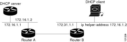
Forwarding UDP
Broadcasts to a DHCP Server Using a Helper Address demonstrates the process. The DHCP
client broadcasts a request for an IP address and additional configuration
parameters on its local LAN. Acting as a DHCP relay agent, Router B picks up
the broadcast, changes the destination address to the DHCP server's address and
sends the message out on another interface. The relay agent inserts the IP
address of the interface, on which the
into the gateway address (giaddr) field of the DHCP packet, which
enables the DHCP server to determine which subnet should receive the offer and
identify the appropriate IP address range. The relay agent unicasts the
messages to the server address, in this case 172.16.1.2 (which is specified by
the helper address in the relay profile).
Figure 1. Forwarding UDP
Broadcasts to a DHCP Server Using a Helper Address
How to Configure and Enable DHCP Relay Agent
This section contains the following tasks:
Configuring and Enabling DHCP Relay Agent with DHCP MAC Address Verification
This section discusses how to configure and enable DHCP Relay Agent with DHCP MAC address verification.
Configuration
Example
Router# configure

Router(config)# dhcp ipv4
/* Configures DHCP for IPv4 and enters the DHCPv4 configuration submode. */

Router(config-dhcpv4)# profile client relay
/* Enables DHCP relay profile */

Router(config-dhcpv4)# client-mac-mismatch action drop
/* Enables MAC address verification. If MAC address in the DHCPv4 protocol header does not match the L2 header source MAC address in the DHCPv4 relay profile,
 the frame is dropped  */

Router(config-dhcpv4-relay-profile)# relay information option
/* Inserts the DHCP relay agent information option (option-82 field) in forwarded
BOOTREQUEST messages to a DHCP server. */

Router(config-dhcpv4-relay-profile)# relay information check
/* (Optional) Configures DHCP to check the validity of the relay agent information
option in forwarded BOOTREPLY messages. */

Router(config-dhcpv4-relay-profile)# relay information policy drop
/* (Optional) Configures the reforwarding policy for a DHCP relay agent;
that is, whether the relay agent will drop or keep (using the 'keep' keyword)
 the relay information. */

Router(config-dhcpv4-relay-profile)# relay information option allow-untrusted
/* (Optional) Configures the DHCP IPv4 Relay not to discard BOOTREQUEST packets that have an existing
relay information option and the giaddr set to zero. */

Router(config-dhcpv4-relay-profile)# giaddr policy drop
/* Drops the packet that has an existing nonzero giaddr value. Use the 'replace' keyword
 to replace the existing giaddr value with a value that it generates (the default behavior).  */

Router(config-dhcpv4-relay-profile)# helper-address vrf vrf1 10.1.1.1
/* Forwards UDP broadcasts, including DHCP. */

Router(config-dhcpv4-relay-profile)# commit

Router(config-dhcpv4-relay-profile)# exit
Router(config-dhcpv4)# vrf vrf1 relay profile client
Router(config-dhcpv4)# commit
/* Configures DHCP Relay on a VRF and commits the entire configuration. */
Running Configuration
Confirm your configuration.
Router# show run
Thu May 11 09:00:57.839 IST
Building configuration...
!! IOS XR Configuration 0.0.0
!! Last configuration change at Thu May 11 09:00:54 2017 by annseque
!
dhcp ipv4
vrf vrf1 relay profile client
profile client relay
client-mac-match action drop
helper-address vrf vrf1 10.1.1.1
giaddr policy drop
relay information check
relay information option
relay information policy drop
relay information option allow-untrusted
!
!
DHCP MAC Address Verification
Use the following show command to check if DHCP MAC address is being verified on the router.
Router# show dhcp ipv4 relay statistics raw all
packet_drop_mac_mismatch                      :         0
The output validates that the DHCP MAC address of the packets is verified.
Enabling DHCP Relay
Agent on an Interface
This task describes
how to enable the Cisco IOS XR DHCP relay agent on an interface.
Note
On Cisco IOS XR
software, the DHCP relay agent is disabled by default.
This task describes how to configure
the DHCP relay
agent information option processing capabilities.
A DHCP relay agent may receive a message from another DHCP relay agent that already
contains relay information. By default, the relay information from the previous relay
agent is replaced (using the replace option).
RP/0/RP0/CPU0:router(config-dhcpv4-relay-profile)# relay information option
Enables the system to insert the DHCP relay agent information option (option-82
field) in forwarded BOOTREQUEST messages to a DHCP server.
This option is injected by the relay agent while forwarding
client-originated DHCP packets to the server. Servers recognizing this
option can use the information to implement IP address or other parameter
assignment policies. When replying, the DHCP server echoes the option back
to the relay agent. The relay agent removes the option before forwarding the
reply to the client.
The relay agent information is organized as a single DHCP option that
contains one or more suboptions. These options contain the information known
by the relay agent.
The supported suboptions are:
Remote ID
Circuit ID
Note
This function is disabled by default.
Step 5
relay information check
Example:
RP/0/RP0/CPU0:router(config-dhcpv4-relay-profile)# relay information check
(Optional) Configures DHCP to check
the relay agent
information option in forwarded BOOTREPLY
is
By default, DHCP
the
field in
DHCP reply packets, received from the DHCP server.
Note
Use the relay information check command to reenable this functionality
if the functionality has been disabled.
Step 6
relay information policy {drop |
keep}
Example:
RP/0/RP0/CPU0:router(config)# dhcp relay information policy drop
(Optional) Configures the reforwarding policy for a DHCP relay agent; that is,
whether the relay agent will drop or keep the relay information.
Step 7
relay information option allow-untrusted
Example:
RP/0/RP0/CPU0:router(config-dhcpv4-relay-)# relay information
(Optional) Configures the DHCP IPv4 Relay not to discard
packets that
have an existing relay information option and the giaddr set to zero.
Step 8
commit
Configuring Relay
Agent Giaddr Policy
This task describes
how to configure
for
that already contain a nonzero giaddr attribute.
RP/0/RP0/CPU0:router(config-dhcpv4-relay-profile)# giaddr policy drop
Specifies the
giaddr policy.
replace—Replaces the existing
giaddr value with a value that it generates.
drop—Drops the packet that
has an existing nonzero giaddr value.
Step 5
commit
Configuring a DHCP
Proxy Profile
The DHCP proxy
performs all the functions of a relay and also provides some additional
functions. The DHCP proxy conceals DHCP server details from DHCP clients. The
DHCP proxy modifies the DHCP replies such that the client considers the proxy
to be the server. In this state, the client interacts with the proxy as if it
is the DHCP server.
This task describes
how to configure and enable the DHCP proxy profile.
The value of
the
address argument can be a specific DHCP server address or a
network address (if other DHCP servers are on the destination network segment).
Using the network address enables other servers to respond to DHCP requests.
For multiple
servers, configure one helper address for each server.
Step 5
commit
DHCPv4
Client
The Dynamic Host
Configuration Protocol (DHCP) client functionality enables the router
interfaces to dynamically acquire the IPv4 address using DHCP.
The DHCP provides
configuration parameters to Internet hosts. DHCP consists of two components:
a protocol to deliver
host-specific configuration parameters from a DHCP server to a host.
a mechanism to allocate
network addresses to hosts.
DHCP is built on a
client-server model, where designated DHCP server hosts allocate network
addresses, and deliver configuration parameters to dynamically configured
hosts.
A relay agent is
required if the client and server are not on the same Layer 2 network. The
relay agent usually runs on the router, and is required because the client
device does not know its own IP address initially. The agent sends out a Layer
2 broadcast to find a server that has this information. The router relays these
broadcasts to the DHCP server, and forwards the responses back to the correct
Layer 2 address so that the correct device gets the correct configuration
information.
DHCP has the ability
to allocate IP addresses only for a configurable period of time, called the
lease period. If the client is required to retain this IP address for a longer
period beyond the lease period, the lease period must be renewed before the IP
address expires. The client renews the lease based on configuration that was
sent from the server. The client unicasts a REQUEST message using the IP
address of the server. When a server receives the REQUEST message and responds
with an ACK message. The lease period of the client is extended by the lease
time configured in the ACK message.
Restrictions and
Limitations
DHCP client can be enabled
only on management interfaces.
Either DHCP or static IP can
be configured on an interface.
Enabling DHCP Client on an Interface
The DHCPv4 or DHCPv6 client can be enabled at an interface level. The DHCP component receives a notification when DHCPv4 or
DHCPv6 is enabled or disabled on an interface.
The DHCP proxy functionality is now available on the Pseudowire Headend (PWHE) interfaces. By using PWHE as a proxy in the
DHCP process, this feature provides enhanced security for DHCP servers by preventing them from directly receiving client requests,
and protecting the DHCP server from external attacks, such as Denial of Service (DoS). Also, because the DHCP-proxy functionality
is enabled and centralised at the Service-side-PE (Provider Edge) devices, it simplifies the on-premise network management
solutions.
The feature introduces these changes:
YANG Data Model:
New XPaths for:
platforms/panini/plat_mdata/scripts/role_mdata.pl
Overview of DHCP Proxy on PWHE Interfaces
The DHCP on PWHE interfaces feature enables you to configure the DHCP functionality, such as DHCP server, relay, or proxy
on the PWHE interface. The Cisco IOS XR Release 7.6.3 introduces the DHCP proxy functionality.
The DHCP proxy conceals DHCP server details from DHCP clients and modifies the DHCP replies such that the client considers
the proxy to be the server. In this state, the client interacts with the proxy as if it is the DHCP server. Because this functionality
is enabled and centralised at the Service-side-PE (Provider Edge) devices, the costs are lower by eliminating the need for
an extra Layer 3 (L3) router at your branch site, and simplifying the on-premise solutions.
Note
This feature is only supported on the Cisco IOS XR 64-Bit operating system.
Some of the key benefits of the DHCP proxy services are:
It minimizes the L3 devices needed at the end-customer premises, leading to lower costs.
It simplifies the connectivity of enterprise branch sites requiring LAN DHCP services from their service provider.
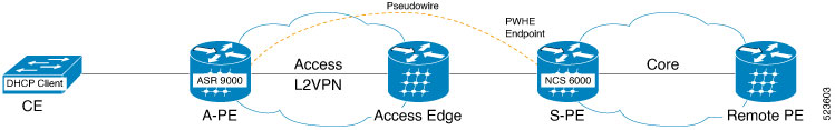
Consider a topology, where:
You have an ASR 9000 router facing the access side, also known as the Access-side Provider Edge (A-PE). And an NCS 6000 router
facing the core side, also known as Service-side Provider Edge (S-PE).
You create a PWHE tunnel between these two routers. The PWHE tunnel originates at L2 on the ASR 9000 router and terminates
at L3 on the NCS 6000 router
Then, configure EVPN-VPWS cross-connect between the NCS 6000 router and the ASR 9000 router
You can configure the NCS 6000 router as a DHCP proxy on the PWHE main interface or sub-interface.
The access-side router carries the traffic in its native form; that is, Ethernet frames with or without VLAN tagging, depending
on whether you are creating a VLAN-based pseudowire or an Ethernet-based pseudowire.
Figure 2. DHCP Proxy Functionality for PWHE Interfaces
If you configure the NCS 6000 router as a DHCP server on the PWHE interface, it processes the request received from the DHCP
client. The DHCP server accepts address assignment requests and renewals, and assigns the IP addresses from predefined groups
of addresses contained within Distributed Address Pools (DAPS). You can also configure the DHCP server to provide additional
information to the requesting client, such as subnet mask, domain-name, the IP address of the DNS server, the default router,
and other configuration parameters.
If you configure the NCS 6000 router as a DHCP proxy on the PWHE interface, it forwards the request received from the DHCP
client to the remote server. The remote server processes the request and provides information back to the DHCP proxy server.
Note
This feature supports both DHCP IPv4 and IPv6 addresses.
Configure DHCP on Pseudowire Headend
To configure DHCP on Pseudowire Headend feature, perform the following tasks:
Configure PWHE on Service-side Provider Edge (S-PE) and Access-side Provide Edge (A-PE)
Configure DHCP on S-PE
Configure PWHE on both S-PE and A-PE
This section describes how you can configure pseudowire headend on both S-PE and A-PE.
The show command outputs given in this section display the details of the configuration of PW Ethernet interface and cross-connect,
and the status of their configuration.
Router#  show l2vpn xconnect

Legend: ST = State, UP = Up, DN = Down, AD = Admin Down, UR = Unresolved,
        SB = Standby, SR = Standby Ready, (PP) = Partially Programmed

XConnect                   Segment 1                       Segment 2
Group      Name       ST   Description            ST       Description            ST
------------------------   -----------------------------   -----------------------------
evpn_vpws  vpws_1     UP   PE2                    UP       EVPN 25,172.16.0.1   UP

-------------------------------------------------------------------------------------------------------------------------------------
Configure DHCP Proxy
Perform these tasks to configure DHCP proxy on PWHE interface.
Geographical Redundancy By Using a Session Redundancy Group (SERG)
In large scale network implementations, it becomes essential to have redundancy between routers that share the same core network
(IP and MPLS), but are geographically apart. A redundancy thus achieved is known as geographical redundancy, and often consists
of a switchover (SO) from the active (primary) router to the standby (subordinate) router.
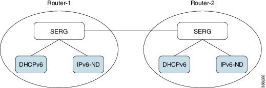
To achieve geographical redundancy for IPv6 Neighbor Discovery (ND) entries, or for DHCPv6 bindings, we use a Session Redundancy
Group (SERG). A SERG comprises of sessions mapped to the access interfaces on the active RP of the router. If a single SERG
is configured on the active RPs of the primary and subordinate routers, then the router hosting the primary SERG serves as
the primary, and the router hosting the subordinate SERG serves as the subordinate. This is illustrated in the following
figure.
Figure 3. Geo Redundancy with a Single SERG
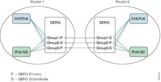
When multiple SERGs are configured on the active RPs, you could have both primary and subordinate SERGs on a single router.
This is illustrated in the following figure.
Figure 4. Geo Redundancy with Multiple SERGs
Each router has an inbuilt redundancy between the RPs. When the active RP fails, the session (s) is transferred to the standby
RP. This is known as a failover (FO).
The Session Redundancy Manager (SERM) runs on the active RP of both primary and subordinate routers. The SR clients running
on the routers interact with the Session Redundancy Infrastructure (Session Redundancy Agent (SRA) and the Session Redundancy
Library (SRL)).
The various components and their functions are briefly described as follows:
Session Redundancy Manager (SERM): The SERM runs as a separate process on the active RP and manages the SERG configuration. The SERM peers with other routers
that need to form a redundancy relationship, and establishes a point-to-multipoint communication channel to Session Redundancy
Agents (SRAs) on the RP.
Session Redundancy Agent (SRA): One or more SRAs run as a a separate process on the active RP and supported line cards. A SRA acts on the SERG configuration,
setting up operational context and database tables. The SRA implements the state machine for primary/subordinate selection
and role change and orchestrates it using the TCP channel and provided APIs.The SRA receives the session entries on the primary
router and updates its database prior to synchronizing with the database on the subordinate router. The SRA orchestrates the
session context setup on the subordinate router during the FO or SO. The SRA maintains a separate session database for each
session client configured in the SERG.
Note
The SRA works only on specific, defined keys, such as the IPv6 address, DHCPv6 client ID, and so on. Any undefined session
data is handled as opaque data by the SRA. The respective session components must provide their access library to the SRA
for handling any transformation or data retrieval.
Session Redundancy Library (SRL): The SRL is used by session components for communicating with the SRA. The SRL uses IPC semantics for communicating with
the SRA. SERG clients use an asychronous API for storing and retrieving the session state from the SRL.
You can configure object tracking for one or more access interfaces in the SERG to enable automatic switchovers when an interface
goes down. For more information on this configuration, see the BNG Command Reference Guide for Cisco ASR 9000 Series Routers.
Limitations for SERG
If the Address Cached in the primary router: When the device configured as a primary router loses connectivity with the device
configured as a subordinate router, the primary router continues to provide addresses assigned to the group. If one or more
subscribers restart, the previously assigned IP addresses remain in the cache until communication is restored between both
SERG entities. This situation could potentially exhaust the address pool if many subscribers frequently disconnect and reconnect,
if a few subscribers continuously flap, or if the clear subscribers command is used.
If a device is configured as a subordinate router: This device does not provide any address if the connectivity to the primary
device is lost. In case this device assumes the role of primary, for example, after a session-redundancy switchover group
was executed or for any other reason, there could be situations where address duplication occurs.
Guidelines for SERG
The connectivity between SERG devices should be stable, as communication occurs over a TCP session using port 4001. It is
good practice to prioritize this traffic.
In the event of a prolonged disconnection between devices configured for SERG, it is advisable to configure a peer removal
due to the caching mechanism. During the disconnection, addresses provided by the pool are tagged as local. Once the connection
is restored, they will be tagged as local and remote.
Configuring and Verifying Session Redundancy for DHCPv6 Clients
Use the following procedure to configure geo-redundancy through session redundancy for DHCPv6 clients.
In this example, we configure Router 1 as Primary and Router 2 as Subordinate.
On Routers R1 and R2, enter the global configuration mode and configure session redundancy by specifying Loopback 0 as the
source interface.
The hold timer values on Routers R1 and R2 must match for them to peer with each other.
Configure the session redundancy group by specifying the preferred role as Primary for Router R1 using the master keyword, and as subordinate for Router R2 using the slave keyword.
Router R1:
Router(config)# session redundancy group 1
Router(config-session-red-group)# preferred-role master
Router(config-session-red-group)# hold-timer 7
Router(config-session-red-group)# peer 2.2.2.2
Router(config-session-red-group)# revertive-timer 5 maximum 15
Router(config-session-red-group)# interface-list
Router(config-session-red-grp-intf)# interface GigabitEthernet0/1/0/0 id 1
Router R2:
Router(config)# session redundancy group 1
Router(config-session-red-group)# preferred-role slave
Router(config-session-red-group)# hold-timer 7
Router(config-session-red-group)# peer 1.1.1.1
Router(config-session-red-group)# revertive-timer 5 maximum 15
Router(config-session-red-group)# interface-list
Router(config-session-red-grp-intf)# interface GigabitEthernet0/1/0/0 id 1
Note
The hold timer, revertive timer, and interface ID values on Routers R1 and R2 must match for them to peer with each other.
Exit to the global configuration mode and commit your configuration on Routers R1 and R2.
Router(config)# commit
Confirm your configuration on Router R1.
Router# show running-config session-redundancy
...
session-redundancy
 source-interface Loopback0
 hold-timer 5
 group 1
  preferred-role master
  hold-timer 7
  peer 2.2.2.2
  revertive-timer 5 maximum 15
  interface-list
   interface GigabitEthernet0/1/0/0 id 1
  !
 !
!
Confirm your configuration on Router R2.
Router# show running-config session-redundancy
...
session-redundancy
 source-interface Loopback0
 hold-timer 5
 group 1
  preferred-role slave
  hold-timer 7
  peer 1.1.1.1
  revertive-timer 5 maximum 15
  interface-list
   interface GigabitEthernet0/1/0/0 id 1
  !
 !
!
Verify the session redundancy group on the routers by running the following show commands.
Router# show session-redundancy group
...
Session Redundancy Agent Group Summary
Flags    : E - Enabled, D - Disabled, M - Preferred Master, S - Preferred Slave
           H - Hot Mode, W - Warm Mode, T - Object Tracking Enabled
P/S      : Peer Status
           I - Initialize, Y - Retry, X - Cleanup, T - Connecting
           L - Listening, R- Registered, C - Connected, E - Established
I/F Count: Interface Count
SS Count : Session Count
----------------------------------------------------------------------------------------------------------------------
   Node Name   | Group ID | Role | Flags  |         Peer Address        | P/S | I/F Count |  SS Count  | Sync Pending
----------------------------------------------------------------------------------------------------------------------
 0/1/CPU0               1  Master   EMH-   2.2.2.2                         E            1           0               0
----------------------------------------------------------------------------------------------------------------------
Session Summary Count(Master/Slave/Total): 0/0/0
Router# show session-redundancy group 1
...
Session Redundancy Group ID: 1
  Description         : <<not-configured>>
  Status              : Enabled

  Init-Role           : Master
  Negotiated-Role     : Master
  Current-Role        : Master

  Hold Time           : 7
  Revert Time         : 5

  Tracking Status     : Enabled
    Core-Tracking     : <<not-configured>>
      Status          : n/a
    Access-Tracking   : <<not-configured>>
      Status          : n/a

  Peer:
    IP-address        : 2.2.2.2
    Status            : Established
    Role(Init/Neg/Cur): Slave/Slave/Slave
    Tracking Status   : Up

    Last Neg-Time     : 2017 Mar  2 18:14:42
    Last Up-Time      : 2017 Mar  2 18:14:42
    Last Down-Time    : 2017 Mar  2 18:14:26

  Switchover:
    Last Switchover   : 2017 Mar  2 18:14:42       Reason         : Peer Up
    Switchover Count  : 1
    Hold Time         : Not-Running
    Revert Time       : Not-Running

  Session Statistics:
    Count             : 0                          Slave-Upd-Fail : 0
    Pending Update    : 0                          Pending Delete : 0
    Client:
      IPv6ND          : 0
      DHCPv6          : 0

  Interface Count     : 1
    GigabitEthernet0/1/0/0                         Map-ID         : 1
Router# show session-redundancy summary interface
...
Session Redundancy Interface Summary
Status: E - Exists, F - Forward Reference
-----------------------------------------------------------------------------
       Interface Name                  | Status | Group ID | Map ID |  Role
-----------------------------------------------------------------------------
 GigabitEthernet0/1/0/0                   E              1        1   Master
-----------------------------------------------------------------------------
Verify the SRG session information on the routers.
Router# show session-redundancy agent interface
...
Session Redundancy Agent Interface
Status   : F - Forward Referenced, S - Stale, R - Registered,
           A - CAPS Added, O - Resource Owned, P - EOMS Pending
           C - Pending CAPS Remove, U - Pending Reg Disable
Err Stats: Enable - Disable - Caps Add - Caps Remove - Attr Updated
-----------------------------------------------------------------------------------------
       Interface Name           |  ID  | Group ID | Role  |  Status  | Oper  | Err Stats
-----------------------------------------------------------------------------------------
 GigabitEthernet0/1/0/0               1         1   Master  --RA----   -----  0-0-0-0-0
---------------------------------------------------------------------------------------
Router# show session-redundancy agent statistics
...
Session Redundancy Agent Summary - Node 0/0/CPU0
Process State : ActiveSource Interface : Loopback0
VRF Name : default
IPv4 Address : 1.1.1.1
IPv6 Address : 192::2
Restart Client Sync In Progress : No
Client Init Sync TimeStamp : -
Restart Peer Sync In Progress : No
Peer Init Sync TimeStamp : -
Sync in Progress : No
Peer Action Timer : Not-Running
Retry Timer : Not-Running
Interface Status Statistics
Bound to group : 1
Non stale : 0
Pending caps remove : 0
Pending reg disable : 0
Pending other batch oper : 0
Sync in Progress : No
Client Statistics:
Status: U - Connection UP, S - Init-Sync Pending, E - Sync EOD Pending
--------------------------------------------------------------------------------
Comp | Status | Up Timestamp | Down Timestamp | Cleanup Timer
--------------------------------------------------------------------------------
SERGAGT --- - - 0
IPv6ND U-- 2017 Mar 2 18:14:25 - 0
DHCPv6 U-- 2017 Mar 2 18:14:25 - 0
--------------------------------------------------------------------------------
TxList Statistics: Ok Part-Write Clean
------------------------------------------------------------------------------------
Marker Encode : 4 0 4
Command Encode : 0 0 0
Negotiation Encode : 0 0 0
Client Statistics: Ok NotOk
-----------------------------------------------------------------------
Invalid Registration : 0
Invalid DeRegistration : 0
Connection Up Count : 2
Connection Down Count : 0
Message CallBack Count : 2
Message Received : 4 0
Command Message Received : 0 0
Session Message Received : 4 0
Peer Done : 2
Peer Statistics: Ok NotOk
-----------------------------------------------------------------------
Timer Handler : 0
Invalid Registration : 0
Invalid DeRegistration : 0
Message CallBack Count : 0 0
Command Connection Up : 0
Command Connection Down : 0
Session Connection Up : 0
Session Connection Down : 0
Peer Done : 0
-----------------------------------------------------------------------
Verify the DHCPv6 SR client information on the routers.
Router#show session-redundancy agent client dhcpv6
...
Session Redundancy Agent Client Statistics - Node 0/0/CPU0
Component - DHCPv6
Statistics:                                            Ok        NotOk
-------------------------------------------------------------------------------
Sent To Client:
  Command
    Start of Download  - SOD               :            1            0
    End of Download    - EOD               :            1            0
    End of Master Sync - EOMS              :            0            0
    Clear              - All               :            0            0
    Clear              - Selected          :            0            0
    Replay             - All               :            0            0
    Replay             - Selected          :            0            0
  Session                                  :            0            0
    Update                                 :            0            0
    Delete                                 :            0

TxList Operation:
  Encode - Complete Write                  :            0
  Encode - Partial Write                   :            0
  Cleanup CallBack                         :            0
Last Replay Count                          :            0

Received From Client:
  Command
    Start of Download  - SOD   - All       :            1
    Start of Download  - SOD   - Selected  :            0
    End of Download    - EOD   - All       :            1
    End of Download    - EOD   - Selected  :            0
    End of Master Sync - EOMS              :            0
    Clear              - All               :            0
    Clear              - Selected          :            0
    Replay             - All               :            0
    Replay             - Selected          :            0
  Session
    Update                                 :            0            0
    Delete                                 :            0            0
  Negative Acknowledgement                 :            0            0

Client Activity Statistics:
  Active                                   :            1            0
  Deactive                                 :            0            0
  Registration                             :            1            0
  DeRegistration                           :            0
  Connection Down                          :            0
  Cleanup                                  :            0
-------------------------------------------------------------------------------

Session Redundancy Agent Client Statistics - Node 0/1/CPU0
Component - DHCPv6
Statistics:                                            Ok        NotOk
-------------------------------------------------------------------------------
Sent To Client:
  Command
    Start of Download  - SOD               :            1            0
    End of Download    - EOD               :            1            0
    End of Master Sync - EOMS              :            1            0
    Clear              - All               :            0            0
    Clear              - Selected          :            0            0
    Replay             - All               :            0            0
    Replay             - Selected          :            0            0
  Session                                  :            0            0
    Update                                 :            0            0
    Delete                                 :            0

TxList Operation:
  Encode - Complete Write                  :            0
  Encode - Partial Write                   :            0
  Cleanup CallBack                         :            0
Last Replay Count                          :            0

Received From Client:
  Command
    Start of Download  - SOD   - All       :            1
    Start of Download  - SOD   - Selected  :            0
    End of Download    - EOD   - All       :            1
    End of Download    - EOD   - Selected  :            0
    End of Master Sync - EOMS              :            0
    Clear              - All               :            0
    Clear              - Selected          :            0
    Replay             - All               :            0
    Replay             - Selected          :            0
  Session
    Update                                 :            0            3
    Delete                                 :            0            2
  Negative Acknowledgement                 :            0            0

Client Activity Statistics:
  Active                                   :            1            0
  Deactive                                 :            0            0
  Registration                             :            1            0
  DeRegistration                           :            0
  Connection Down                          :            0
  Cleanup                                  :            0
-------------------------------------------------------------------------------

Session Redundancy Agent Client Statistics - Node 0/2/CPU0
Component - DHCPv6
Statistics:                                            Ok        NotOk
-------------------------------------------------------------------------------
Sent To Client:
  Command
    Start of Download  - SOD               :            1            0
    End of Download    - EOD               :            1            0
    End of Master Sync - EOMS              :            0            0
    Clear              - All               :            0            0
    Clear              - Selected          :            0            0
    Replay             - All               :            0            0
    Replay             - Selected          :            0            0
  Session                                  :            0            0
    Update                                 :            0            0
    Delete                                 :            0

TxList Operation:
  Encode - Complete Write                  :            0
  Encode - Partial Write                   :            0
  Cleanup CallBack                         :            0
Last Replay Count                          :            0

Received From Client:
  Command
    Start of Download  - SOD   - All       :            1
    Start of Download  - SOD   - Selected  :            0
    End of Download    - EOD   - All       :            1
    End of Download    - EOD   - Selected  :            0
    End of Master Sync - EOMS              :            0
    Clear              - All               :            0
    Clear              - Selected          :            0
    Replay             - All               :            0
    Replay             - Selected          :            0
  Session
    Update                                 :            0            0
    Delete                                 :            0            0
  Negative Acknowledgement                 :            0            0

Client Activity Statistics:
  Active                                   :            1            0
  Deactive                                 :            0            0
  Registration                             :            1            0
  DeRegistration                           :            0
  Connection Down                          :            0
  Cleanup                                  :            0
You have successfully configured and verified geo redundancy using session redundancy groups for DHCPv6 clients.
Managing Session Redundancy Groups
After you have configured and verified the session redundancy groups (SERGs), you can use the commands in this section to
trigger a manual switchover, trigger a manual synchronization, or clear sessions for all or a specific SERG.
Triggering a Manual Switchover
After you have configured SERGs on the primary and subordinate routers, if you want to remove/replace the primary router,
you can trigger a manual switchover from the primary to the subordinate by running the following commands.
Note
The following commands can be executed only on the primary router.
To trigger a redundancy switchover for all SERGs, run the following command.
To trigger a redundancy switchover for a specific SERG, run the following command.
RP/0/RP0/CPU0:router# session redundancy switchover group 210
Triggering Manual Synchronization
If the sessions between the primary and subordinate routers are not getting synchronized, either because of some change in
the network topology, or some network latency, you can trigger synchronization manually by running the following commands.
Note
The following commands can be executed on either the Primary or the Subordinate router.
To trigger a redundancy synchronization for all SERGs, run the following command.
To trigger a redundancy synchronization for a specific SERG, run the following command.
RP/0/RP0/CPU0:router# session redundancy synchronize group 210
Clearing Sessions in a SERG
If you want to clear the existing sessions on the primary and subordinate routers, either because of a switchover, or a change
in network topology, you can run the following commands.
Note
The following commands can be executed on either the primary or the subordinate router.
When issued on the subordinate, the session context is deleted from the router and a synchronization is requested with the
primary. If the router is in hot-standby mode, the sessions are deleted on the subordinate.
When issued on the primary, the session entries are deleted first on the primary and later on the subordinate. The SRA then
requests a fresh session from the SR client, which is eventually synchronized with the subordinate.
To clear sessions for all SERGs, run the following command.
RP/0/RP0/CPU0:router# clear session-redundancy
To clear sessions for a specific SERG, run the following command.
RP/0/RP0/CPU0:router# clear session-redundancy group 1
Configuring and Verifying Session Redundancy for IPv6 ND Clients
Use the following procedure to configure geo-redundancy through session redundancy for IPv6 ND clients.
In this example, we configure Router 1 as Primary and Router 2 as Subordinate.
On Routers R1 and R2, enter the global confiiguration mode and configure session redundancy by specifying Loopback 0 as the
source interface.
The hold timer values on Routers R1 and R2 must match for them to peer with each other.
Configure the session redundancy group by specifying the preferred role as Primary for Router R1 using the master keyword, and as subordinate for Router R2 using the slave keyword.
Router R1 :
RP/0/RP0/CPU0:router(config)# session redundancy group 1RP/0/RP0/CPU0:router(config-session-red-group)# preferred-role masterRP/0/RP0/CPU0:router(config-session-red-group)# hold-timer 7RP/0/RP0/CPU0:router(config-session-red-group)# peer 2.2.2.2RP/0/RP0/CPU0:router(config-session-red-group)# revertive-timer 5 maximum 15RP/0/RP0/CPU0:router(config-session-red-grp-intf)# interface GigabitEthernet0/1/0/0 id 1
Router R2:
RP/0/RP0/CPU0:router(config)# session redundancy group 1RP/0/RP0/CPU0:router(config-session-red-group)# preferred-role slaveRP/0/RP0/CPU0:router(config-session-red-group)# hold-timer 7RP/0/RP0/CPU0:router(config-session-red-group)# peer 1.1.1.1RP/0/RP0/CPU0:router(config-session-red-group)# revertive-timer 5 maximum 15RP/0/RP0/CPU0:router(config-session-red-grp-intf)# interface GigabitEthernet0/1/0/0 id 1
Note
The hold timer, revertive timer, and interface ID values on Routers R1 and R2 must match for them to peer with each other.
Exit to the global configuration mode and commit your configuration on Routers R1 and R2.
RP/0/RP0/CPU0:router(config)# commit
Confirm your configuration on Router R1 (Primary).
RP/0/RP0/CPU0:router# show running-config session-redundancy
...
session-redundancy
 source-interface Loopback0
 hold-timer 5
 group 1
  preferred-role master
  hold-timer 7
  peer 2.2.2.2
  revertive-timer 5 maximum 15
   interface GigabitEthernet0/1/0/0 id 1
  !
 !
!
Confirm your configuration on Router R2.
RP/0/RP0/CPU0:router# show running-config session-redundancy
...
session-redundancy
 source-interface Loopback0
 hold-timer 5
 group 1
  preferred-role slave
  hold-timer 7
  peer 1.1.1.1
  revertive-timer 5 maximum 15
   interface GigabitEthernet0/1/0/0 id 1
  !
 !
!
Verify the session redundancy group on the routers by running the following show commands.
RP/0/RP0/CPU0:router# show session-redundancy group
...
Session Redundancy Agent Group Summary
Flags    : E - Enabled, D - Disabled, M - Preferred Master, S - Preferred Slave
           H - Hot Mode, W - Warm Mode, T - Object Tracking Enabled
P/S      : Peer Status
           I - Initialize, Y - Retry, X - Cleanup, T - Connecting
           L - Listening, R- Registered, C - Connected, E - Established
I/F Count: Interface Count
SS Count : Session Count
----------------------------------------------------------------------------------------------------------------------
   Node Name   | Group ID | Role | Flags  |         Peer Address        | P/S | I/F Count |  SS Count  | Sync Pending
----------------------------------------------------------------------------------------------------------------------
 0/1/CPU0               1  Master   EMH-   2.2.2.2                         E            1           0               0
----------------------------------------------------------------------------------------------------------------------
Session Summary Count(Master/Slave/Total): 0/0/0
RP/0/RP0/CPU0:router# show session-redundancy group 1
...
Session Redundancy Group ID: 1
  Description         : <<not-configured>>
  Status              : Enabled

  Init-Role           : Master
  Negotiated-Role     : Master
  Current-Role        : Master

  Hold Time           : 7
  Revert Time         : 5

  Tracking Status     : Enabled
    Core-Tracking     : <<not-configured>>
      Status          : n/a
    Access-Tracking   : <<not-configured>>
      Status          : n/a

  Peer:
    IP-address        : 2.2.2.2
    Status            : Established
    Role(Init/Neg/Cur): Slave/Slave/Slave
    Tracking Status   : Up

    Last Neg-Time     : 2017 Mar  2 18:14:42
    Last Up-Time      : 2017 Mar  2 18:14:42
    Last Down-Time    : 2017 Mar  2 18:14:26

  Switchover:
    Last Switchover   : 2017 Mar  2 18:14:42       Reason         : Peer Up
    Switchover Count  : 1
    Hold Time         : Not-Running
    Revert Time       : Not-Running

  Session Statistics:
    Count             : 0                          Slave-Upd-Fail : 0
    Pending Update    : 0                          Pending Delete : 0
    Client:
      IPv6ND          : 0
      DHCPv6          : 0

  Interface Count     : 1
    GigabitEthernet0/1/0/0                         Map-ID         : 1
RP/0/RP0/CPU0:router# show session-redundancy summary interface
...
Session Redundancy Interface Summary
Status: E - Exists, F - Forward Reference
-----------------------------------------------------------------------------
       Interface Name                  | Status | Group ID | Map ID |  Role
-----------------------------------------------------------------------------
 GigabitEthernet0/1/0/0                   E              1        1   Master
-----------------------------------------------------------------------------
Verify the SRG session information on the routers.
The Cisco
Technical Support website contains thousands of pages of searchable technical
content, including links to products, technologies, solutions, technical tips,
and tools. Registered Cisco.com users can log in from this page to access even
more content.

 Feedback