Information About High Availability on the Cisco CSR 1000v
Overview of High Availability for the CSR 1000v on Microsoft Azure
You can deploy the Cisco CSR 1000v between the front-end and back-end subnets. The Cisco CSR 1000v represents a single point of failure for access to back-end resources. For example, you can configure two Cisco CSR 1000vs and connect them in parallel between the front and back end subnets. Each of these Cisco CSR 1000vs is known a peer router.
The routing table for the back-end subnet contains entries that point to the next hop router, which is one of the two Cisco CSR 1000vs. The routing protocol that is configured on the Cisco CSR 1000v determines the path of the downstream traffic.
The peer Cisco CSR 1000v routers communicate with one another over a tunnel using the Bi-directional Forwarding Detection (BFD) protocol. The BFD generates an event if connectivity between the peer routers is lost. This event causes the active Cisco CSR 1000v to update the entries in the route table to point to itself as the default router. The routing table controls the upstream traffic of the Cisco CSR 1000v. An active router is the next-hop router for either an individual route or all routes in the user-defined route table.
In cloud environments, it is common for virtual networks to implement a simplistic mechanism for routing, which is based on a centralized route table. You can create multiple route tables. Each route table has a subnet that is assigned, which is a source of route information. In Microsoft Azure, the route table is populated automatically and includes one or more individual routes depending upon the network topology. You can configure the routes in the route table. You can also configure using the GUI on the Microsoft Azure portal web site, entering Azure CLI commands, or by using the programmatic APIs (for example, a REST API).
Using a centralized route table for a subnet allows a pair of Cisco CSR 1000v routers to operate in a redundant fashion. You can deploy two Cisco CSR 1000vs can be deployed in the same virtual network and have interfaces that are directly connected to subnets within the virtual network. You can add routes to the route table to point to one of the two redundant CSR 1000vs. So at any given time, one of the two CSRs is the next hop router for a subnet. This router is called the active router for the subnet and the other (peer) router is the passive router.
A subnet has a centralized route table, which allows two Cisco CSR 1000v routers to operate in a redundant mode. You can deploy two Cisco CSR 1000vs in the same virtual network with their interfaces that are directly connected to subnets in the virtual network. You can add routes to the route table to point to one of the two redundant CSR 1000vs. At any given time, one of the two Cisco CSR 1000v's serves as the next hop router for a subnet. This router is called the active router for the subnet. The peer router is referred to as the passive router. The “active” Cisco CSR 1000v is the next hop for a given route destination.
Failure detection is a mechanism that is used by a Cisco CSR 1000v to detect whether its peer Cisco CSR 1000v is operating properly. The Bidirectional Failure Detection (BFD) protocol is used. An IP tunnel is created between the two peer routers. Each router periodically sends a BFD protocol message to the other router. If one router fails to receive a BFD message from its peer for some period, it concludes the peer router has failed.
If the active router fails, the route table for the subnet can be dynamically updated to change the next hop address for one or more routes so that they refer to the passive router. If the peer router detects the failure of the active router, the peer Cisco CSR 1000v router uses the programmatic API to update the route table entries.
 Note |
The Microsoft Azure route table updates may take up to one minute to take effect and may cause a delay in the High Availability failover. |
For a route table entry, configure which of the two Cisco CSR 1000v routers is the primary router. The other router is the passive router if it is configured as a secondary router. By default, all routes are configured as secondary.
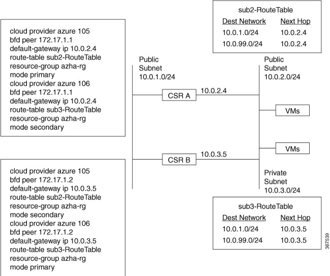
Consider the simple network diagram that is shown in the following figure. The topology in this figure is an example of 1-for-1 redundancy. For more information, see the Redundancy Topologies section.
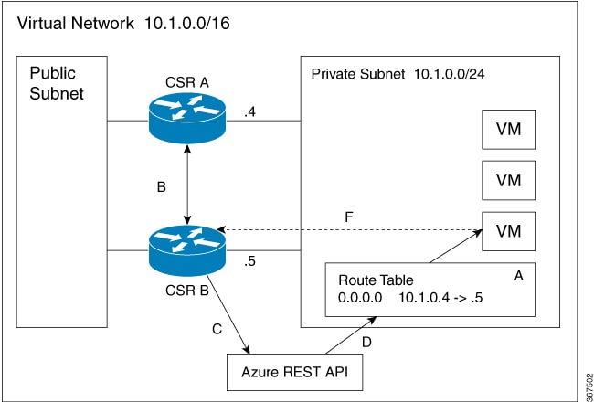
The Private Subnet has an address block of 10.1.0.0/24. CSR A and CSR B provide a redundant path for traffic leaving this leaf subnet. The subnet has a route table that provides the route information to virtual machines which are attached to the Private Subnet. Initially the default route in the route table records the IP address of the next hop router as 10.1.0.4 (CSR A). All traffic leaving the subnet goes through CSR A. CSR A is currently the active router for the default route. Then, CSR A fails and CSR B detects the failure because it stops receiving BFD protocol messages from CSR A. CSR B writes to the route table via a REST API to change the default route to the interface of CSR B on the 10.1.0.0/24 subnet, which is IP address 10.1.0.5. CSR B becomes the active router for the default route.
|
Step |
Description |
|---|---|
|
A |
CSR A with address 10.1.0.4 is the active router for the 15.0.0.0 network. |
|
B |
CSR A fails. CSR B detects the failure using the BFD protocol. |
|
C |
CSR B uses an HTTP request to the Azure REST API. |
|
D |
Azure updates the 15.0.0.0 route in the user-defined route table to the IP address of CSR B. |
|
E |
Virtual machines see the route table update. |
|
F |
Packets from the virtual machines are now directed to CSR B. |
Redundancy Topologies
Two different redundancy topologies are supported:
1-for-1 redundancy topology If both of the Cisco CSR 1000v routers have a direct connection to the same subnet, the routers provide 1-for-1 redundancy. All the traffic that is intended for a Cisco CSR 1000v only goes to the active router. The active router is the next-hop router for a subnet. The other router is the passive router for all the routes.
Load sharing topology In this topology, both the Cisco CSR 1000v routers have direct connections to different subnets within the same virtual network. Traffic from subnet A goes to router A and traffic from subnet B goes to router B. Each of these subnets is bound to different route tables. If router A fails, the route table for subnet A is updated. Instead of router A being the next hop, the route entry is changed to router B as the next hop. If router B fails, the route table for subnet B is updated. In the same manner if router B fails, the route table now includes router A as the next hop router.
Redundancy Nodes
A redundancy node is a set of configuration parameters that specifies an entry in a route table. The next hop of a route is updated when an active router fails. Configuring a redundancy node requires the following information:
|
Parameter |
Description |
|---|---|
|
Route Table |
The route may include the following details:
|
|
Credentials |
Authentication for the Cisco CSR 1000v, which gives it the authorization to update entries in the route table. Each cloud provider may handle the process of obtaining and specifying the credentials differently. |
|
Next Hop |
Next hop address that is written to the routing table entry when a trigger event occurs. It is usually the next hop address of the interface for the Cisco CSR 1000v, on the subnet that is being protected. |
|
Peer Router |
Identifies the redundant router that forwards traffic for this route, after a failure occurs on this router. |
|
Router Role |
Identifies whether the redundancy node serves in a primary or secondary role. This is an optional parameter. If not specified, the router role defaults to a secondary role. |
Event Types
The high availability feature recognizes and responds to three types of events:
Peer Router Failure
When the peer route fails, it is detected as a Peer Router Failure event. In response to this event, the event handler writes the route entry with the next hop address that is defined in the redundancy node. To enable this event to be generated, configure the BFD protocol to a peer router and associate the BFD peer with one or more redundancy nodes.
Revert to Primary Router
After a router recovers from a failure, the Revert to Primary Router event occurs. The purpose of the event is to ensure that in the route table entry for the redundancy node has this router defined as the primary router.
Redundancy Node Verification
Use the Redundancy Node verification event to verify the ability of the event handler to execute functions. The event handler detects a Redundancy Node verification event and reads the route entry that is specified by the redundancy node. The event handler writes the same data back to the route entry. The Redundancy Node verification event is triggered by executing a script (manually or programatically). For further information about verification events, see User-Defined Triggers in the Advanced Programming for High Availability on Microsoft Azure section.
New and Updated Information About High Availability
The first version of high availability in the Azure cloud—HA Version 1—was introduced in Cisco IOS XE Everest 16.5.1.
Note |
The second version of high availability --HA Version 2-- is available using Cisco IOS XE Fuji 16.9.2 or later. HA Version 2 supports several new features, and a new configuration and deployment mechanism. It is recommended that you migrate to HA version 2, as support for HA version 1 will be removed from a future IOS release. |
The following functions are introduced in HA Version 2:
Active–Active Operation
You can configure both Cisco CSR 1000vs to be active simultaneously, which allows for load sharing. In this mode of operation, each route in a route table has one of the two routers serve as the primary router and the other router serves as a secondary router. To enable load sharing, take all the routes and split them between the two Cisco CSR 1000vs.
Reversion to Primary CSR After Fault Recovery
You can designate a Cisco CSR 1000v as the primary router for a given route. While this Cisco CSR 1000v is up and running, it is the next hop for the route. If the Cisco CSR 1000v fails, the peer Cisco CSR 1000v takes over as the next hop for the route, maintaining network connectivity. When the original router recovers from the failure, it reclaims ownership of the route and is the next hop router.
New Configuration and Deployment Mechanism
In HA version 2, the implementation of HA has been moved out of the Cisco IOS XE code and runs in the guestshell container. For further information on the guestshell, see the "Guest Shell" section in the Programmability Configuration Guide. In HA version 2, the configuration of redundancy nodes is performed in the guestshell using a set of Python scripts.
Authentication by Microsoft Managed Service Identity
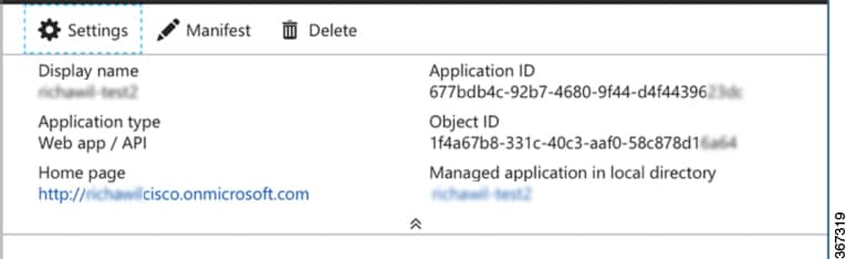
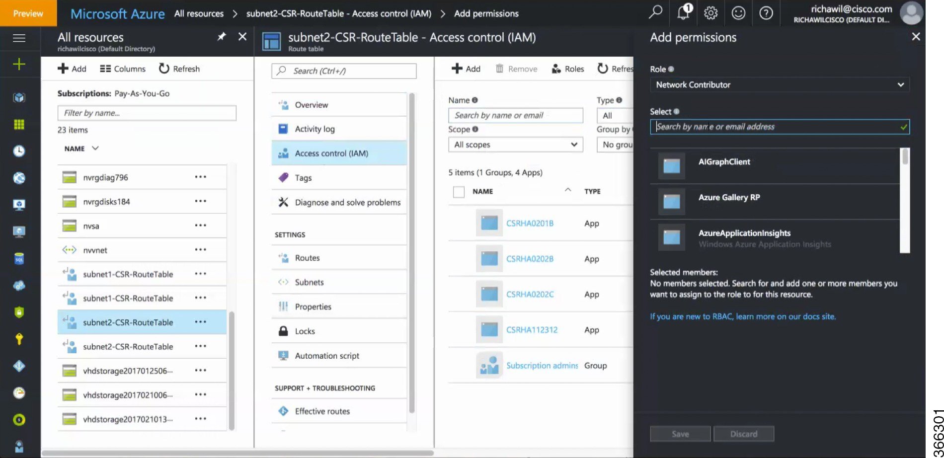
The Azure Active Directory(AAD) must authenticate a Cisco CSR 1000v to access and update route tables in the Azure network. (In HA version 1, authentication is achieved by creating a Cisco CSR 1000v application in Azure Active Directory (AAD) to represent the Cisco CSR 1000v.)
Microsoft has a Managed Service Identity (MSI) service that automates the creation of an application for a virtual machine. For more information on MSI, see: https://docs.microsoft.com/en-us/azure/active-directory/managed-service-identity/overview. HA version 2 uses the MSI service to authenticate the Cisco CSR 1000v. You do not need to manually create the Cisco CSR 1000v application.
Note |
HA version 2 also continues to support authentication in Azure Active Directory (AAD). |
User-Supplied Scripts
The guestshell is a container in which you can deploy your own scripts. HA Version 2 exposes a programming interface to user-supplied scripts, so you can write scripts that can trigger both failover and reversion events. You can develop your own algorithms and triggers to control which Cisco CSR 1000v provides the forwarding services for a given route.
Migrating from High Availability Version 1 to Version 2
Choose one of the following deployment options for High Availability(HA) on Microsoft Azure, on Cisco IOS XE Fuji 16.9.x:
-
HA Version 1—continues to be supported in Cisco IOS XE Fuji 16.9.x. However, this will be deprecated in all releases later than Cisco IOS XE Fuji 16.9.x.
-
HA Version 2 with Redundancy Node Configuration in Cisco IOS XE. Configuration steps using Cisco IOS XE CLI commands is supported in Cisco IOS XE Fuji 16.9.1 and provides access to the new features in HA version 2. This allows you to continue using your existing redundancy node configurations. However, this deployment option will be deprecated in all releases later than Cisco IOS XE Fuji 16.9.x.
-
HA Version 2 with Redundancy Node Configuration in the guestshell. Configuration steps using guestshell-based Python scripts is supported in Cisco IOS XE Fuji 16.9.1. This is the preferred deployment method. If you currently use Redundancy Node Configuration in Cisco IOS XE, we recommend that, during the period of time that you are using Cisco IOS XE Fuji 16.9.x., you migrate to using Redundancy Node Configuration in the guestshell.
Note
By default, in Cisco IOS XE Fuji 16.9.x, the Cisco CSR 1000v on Microsoft Azure runs HA Version 1. To run HA Version 2, you must manually install the "csr_azure_ha" package in the guestshell.
Differences in High Availability across Cisco IOS XE Releases
The following table shows some of the differences between running high availability in various IOS releases.
|
Aspect |
Cisco IOS XE 16.5.x to IOS XE 16.8.x |
Cisco IOS XE 16.9.x |
Cisco IOS XE 16.10.x or later |
|---|---|---|---|
|
HA Version 1 |
Yes |
Yes |
No |
|
HA Version 2 |
No |
Yes |
Yes |
|
Redundancy node configuration in Cisco IOS XE |
YES |
Yes |
Yes |
|
Redundancy node configuration in guestshell |
No |
Yes |
Yes |
|
Revert back to primary router after recovery |
No |
Yes |
Yes |
|
CSR 1000v authentication by Azure Active Directory |
Yes |
Yes |
Yes |
|
CSR 1000v authentication by Managed Service Interface |
No |
Yes |
Yes |
|
User scripts to update routes |
No |
Yes |
Yes |
Comparison in the Configuration of HA Version 1 and HA Version 2
The following configuration procedures are unchanged between HA Version 1 and HA Version 2:
For configuration of HA Version 1, see Configuring High Availability Version 1 for the CSR 1000v on Microsoft Azure.

 .
.
 Feedback