- Preface
- New and Changed System Management Features
- Configuring Secure Domain Routers on the Cisco IOS XR Software
- Upgrading and Managing Cisco IOS XR Software
- Configuring Disk Backups and Disk Mirroring
- Software Entitlement
- Managing the Router Hardware
- Configuring Flexible Command Line Interface Configuration Groups
- Upgrading FPD
- Configuring Manageability
- Configuring Call Home
- Implementing NTP
- Implementing Object Tracking
- Process Placement
- Implementing Physical and Virtual Terminals
- Implementing SNMP
- Configuring Periodic MIB Data Collection and Transfer
- Implementing CDP
- Prerequisites for Managing Router Hardware
- Displaying Hardware Status
- Displaying SDR Hardware Version Information
- Displaying System Hardware Version Information
- Displaying the Chassis Serial Numbers
- Displaying the Configured Chassis Serial Numbers
- Displaying Software and Hardware Information
- Displaying Router Power Consumption
- Displaying SDR Node IDs and Status
- Displaying Router Node IDs and Status
- Displaying Router Environment Information
- Displaying RP Redundancy Status
- Displaying Field-Programmable Device Compatibility
- RP Redundancy and Switchover
- Reloading, Shutting Down, or Power Cycling a Node
- Flash Disk Recovery
- Using Controller Commands to Manage Hardware Components
- Formatting Hard Drives, Flash Drives, and Other Storage Devices
- Removing and Replacing Cards
Managing the Router Hardware
This chapter describes the command-line interface (CLI) techniques and commands used to manage and configure the hardware components of a router running the Cisco IOS XR software.
For complete descriptions of the commands listed in this module, see Additional References. To locate documentation for other commands that might appear in the course of performing a configuration task, search online in Cisco IOS XR Commands Master List for the Cisco CRS Router.
|
Release |
Modification |
|---|---|
|
Release 2.0 |
This feature was introduced. |
|
Release 3.2 |
Logical router (LR) was first supported. |
|
Release 3.3.0 |
The term logical router (LR) was changed to secure domain router (SDR). |
|
Release 3.5.0 |
Flash disk recovery was implemented. |
This module contains the following topics:
- Prerequisites for Managing Router Hardware
- Displaying Hardware Status
- RP Redundancy and Switchover
- Reloading, Shutting Down, or Power Cycling a Node
- Flash Disk Recovery
- Using Controller Commands to Manage Hardware Components
- Formatting Hard Drives, Flash Drives, and Other Storage Devices
- Removing and Replacing Cards
- Upgrading the CPU Controller Bits
- Additional References
Prerequisites for Managing Router Hardware
You must be in a user group associated with a task group that includes the proper task IDs. The command reference guides include the task IDs required for each command. If you suspect user group assignment is preventing you from using a command, contact your AAA administrator for assistance.
Displaying Hardware Status
This section describes how to display different types of hardware status information.
- Displaying SDR Hardware Version Information
- Displaying System Hardware Version Information
- Displaying the Chassis Serial Numbers
- Displaying the Configured Chassis Serial Numbers
- Displaying Software and Hardware Information
- Displaying Router Power Consumption
- Displaying SDR Node IDs and Status
- Displaying Router Node IDs and Status
- Displaying Router Environment Information
- Displaying RP Redundancy Status
- Displaying Field-Programmable Device Compatibility
Displaying SDR Hardware Version Information
To display hardware version information for the components assigned to a secure domain router (SDR), connect to the appropriate designated secure domain router shelf controller (DSDRSC) and enter the show diag command in EXEC mode. The displayed information includes the card serial number and the ROMMON software version.
The syntax for the show diag command in EXEC mode is:
show diag [node-id | details | summary]
In the following example, the show diag command displays information for all nodes in the SDR:
RP/0/RP0/CPU0:router# show diag

  PLIM 0/1/CPU0 : JACKET CARD
    MAIN:  board type 580070
           800-23819-03 rev C0
           dev N/A
           S/N SAD094401CR
    PCA:   73-8982-06 rev C0
    PID:   CRS1-SIP-800
    VID:   V01
    CLEI:  COUIAAMCAA
    ECI:   134912
    Board State : IOS XR RUN
    PLD:   Motherboard: 0x0025, Processor: 0xda13, Power: N/A
    MONLIB: QNXFFS Monlib Version 3.0
    ROMMON: Version 1.40(20050525:193559)  [CRS-1 ROMMON]
    Interface port config:  0 Ports
    Optical reach type:  Unknown
    Connector type:  MT-P

  NODE 0/1/0 : 4xOC3 POS SPA
    MAIN:  board type 0440
           68-2169-01 rev C0
           dev N/A
           S/N JAB093309PA
    PCA:   73-9313-04 rev B0
    PID:   SPA-4XOC3-POS
    VID:   V01
    CLEI:  IPUIAFNRAA

  NODE 0/1/5 : 8xGE SPA
    MAIN:  board type 044f
           68-2239-01 rev A0
           dev N/A
           S/N SAD0937022J
    PCA:   73-8557-03 rev A0
    PID:   SPA-8X1GE
    VID:   V01
    CLEI:  CNUIAH6AAA

  PLIM 0/6/CPU0 : JACKET CARD
    MAIN:  board type 580070
           800-23819-03 rev C0
           dev N/A
           S/N SAD094203W2
    PCA:   73-8982-06 rev C0
    PID:   CRS1-SIP-800
    VID:   V01
    CLEI:  COUIAAMCAA
    ECI:   134912
    Board State : IOS XR RUN
    PLD:   Motherboard: 0x0025, Processor: 0xda13, Power: N/A
    MONLIB: QNXFFS Monlib Version 3.0
    ROMMON: Version 1.40(20050525:193559)  [CRS-1 ROMMON]
    Interface port config:  0 Ports
    Optical reach type:  Unknown
    Connector type:  MT-P

  NODE 0/6/0 : 4xOC3 POS SPA
    MAIN:  board type 0440
           68-2169-01 rev C0
           dev N/A
           S/N JAB093309MG
    PCA:   73-9313-04 rev B0
    PID:   SPA-4XOC3-POS
    VID:   V01
    CLEI:  IPUIAFNRAA

  NODE 0/6/4 : 8xOC3/OC12 POS SPA
    MAIN:  board type 0404
           68-2164-01 rev 34
           dev N/A
           S/N JAB094706L9
    PCA:   73-9941-02 rev 04
    PID:   SPA-8XOC12-POS
    VID:   V01
    CLEI:  SOUIAA8BAA

  NODE 0/6/5 : 8xGE SPA
    MAIN:  board type 044f
           68-2239-01 rev A0
           dev N/A
           S/N SAD093909GM
    PCA:   73-8557-03 rev A0
    PID:   SPA-8X1GE
    VID:   V01
    CLEI:  CNUIAH6AAA

  NODE 0/RP0/CPU0 : RP
    MAIN:  board type 100002
           800-22921-10 rev B0
           dev 080366, 080181
           S/N SAD093507J8
    PCA:   73-8564-10 rev B0
    PID:   CRS-8-RP
    VID:   V01
    CLEI:  IPUCABWBAA
    ECI:   129507
    Board State : IOS XR RUN
    PLD:   Motherboard: 0x0038, Processor: 0x0038, Power: 0x0000
    MONLIB: QNXFFS Monlib Version 3.0
    ROMMON: Version 1.40(20050525:193559)  [CRS-1 ROMMON]

  NODE 0/RP1/CPU0 : RP
    MAIN:  board type 100002
           800-22921-10 rev B0
           dev 080366, 080181
           S/N SAD093507JP
    PCA:   73-8564-10 rev B0
    PID:   CRS-8-RP
    VID:   V01
    CLEI:  IPUCABWBAA
    ECI:   129507
    Board State : IOS XR RUN
    PLD:   Motherboard: 0x0038, Processor: 0x0038, Power: 0x0000
    MONLIB: QNXFFS Monlib Version 3.0
    ROMMON: Version 1.40(20050525:193559)  [CRS-1 ROMMON]
In the following example, the show diag command displays information for a single node:
RP/0/RP0/CPU0:router# show diag 0/RP0/CPU0

  NODE 0/RP0/CPU0 : RP
    MAIN:  board type 100002
           800-22921-10 rev B0
           dev 080366, 080181
           S/N SAD093507J8
    PCA:   73-8564-10 rev B0
    PID:   CRS-8-RP
    VID:   V01
    CLEI:  IPUCABWBAA
    ECI:   129507
    Board State : IOS XR RUN
    PLD:   Motherboard: 0x0038, Processor: 0x0038, Power: 0x0000
    MONLIB: QNXFFS Monlib Version 3.0
    ROMMON: Version 1.40(20050525:193559)  [CRS-1 ROMMON]
Displaying System Hardware Version Information
To display hardware version information for all or some of the components assigned in a system, connect to the designated shelf controller (DSC) and enter the show diag command in administration EXEC mode. When this command is entered in administration EXEC mode, you can display information on RPs, MSCs or line cards, fabric cards, and system components such as the chassis, fan trays, and power supplies.
 Note | If you enter the show diag command in EXEC mode, the software displays only the hardware assigned to the SDR to which you are connected. |
The syntax for the show diag command in administration EXEC mode is:
show diag [node-id | chassis | details | fans | memory | power-supply | summary]
 Tip | For information on the software version, use the show version command. |
In the following example, the show diag command displays information for all nodes in the system:
RP/0/RP0/CPU0:router(admin)# show diag

  NODE 0/1/SP : MSC(SP)
    MAIN:  board type 500060
           800-25021-05 rev B0
           dev 079239
           S/N SAD09280BS9
    PCA:   73-7648-08 rev B0
    PID:   CRS-MSC
    VID:   V02
    CLEI:  IPUCAC1BAA
    ECI:   132502
    Board State : IOS XR RUN
    PLD:   Motherboard: 0x0025, Processor: 0xda13, Power: N/A
    MONLIB: QNXFFS Monlib Version 3.0
    ROMMON: Version 1.40(20050525:193402)  [CRS-1 ROMMON]

  PLIM 0/1/CPU0 : JACKET CARD
    MAIN:  board type 580070
           800-23819-03 rev C0
           dev N/A
           S/N SAD094401CR
    PCA:   73-8982-06 rev C0
    PID:   CRS1-SIP-800
    VID:   V01
    CLEI:  COUIAAMCAA
    ECI:   134912
    Board State : IOS XR RUN
    PLD:   Motherboard: 0x0025, Processor: 0xda13, Power: N/A
    MONLIB: QNXFFS Monlib Version 3.0
    ROMMON: Version 1.40(20050525:193559)  [CRS-1 ROMMON]
    Interface port config:  0 Ports
    Optical reach type:  Unknown
    Connector type:  MT-P

  NODE 0/1/0 : 4xOC3 POS SPA
    MAIN:  board type 0440
           68-2169-01 rev C0
           dev N/A
           S/N JAB093309PA
    PCA:   73-9313-04 rev B0
    PID:   SPA-4XOC3-POS
    VID:   V01
    CLEI:  IPUIAFNRAA

  NODE 0/1/5 : 8xGE SPA
    MAIN:  board type 044f
           68-2239-01 rev A0
           dev N/A
           S/N SAD0937022J
    PCA:   73-8557-03 rev A0
    PID:   SPA-8X1GE
    VID:   V01
    CLEI:  CNUIAH6AAA

  NODE 0/RP0/CPU0 : RP
    MAIN:  board type 100002
           800-22921-10 rev B0
           dev 080366, 080181
           S/N SAD093507J8
    PCA:   73-8564-10 rev B0
    PID:   CRS-8-RP
    VID:   V01
    CLEI:  IPUCABWBAA
    ECI:   129507
    Board State : IOS XR RUN
    PLD:   Motherboard: 0x0038, Processor: 0x0038, Power: 0x0000
    MONLIB: QNXFFS Monlib Version 3.0
    ROMMON: Version 1.40(20050525:193559)  [CRS-1 ROMMON]

  NODE 0/RP1/CPU0 : RP
    MAIN:  board type 100002
           800-22921-10 rev B0
           dev 080366, 080181
           S/N SAD093507JP
    PCA:   73-8564-10 rev B0
    PID:   CRS-8-RP
    VID:   V01
    CLEI:  IPUCABWBAA
    ECI:   129507
    Board State : IOS XR RUN
    PLD:   Motherboard: 0x0038, Processor: 0x0038, Power: 0x0000
    MONLIB: QNXFFS Monlib Version 3.0
    ROMMON: Version 1.40(20050525:193559)  [CRS-1 ROMMON]

  NODE 0/SM0/SP : FC/S
    MAIN:  board type 400035
           800-23168-05 rev B0
           dev N/A
           S/N SAD0933081S
    PCA:   73-8682-05 rev B0
    PID:   CRS-8-FC/S
    VID:   V01
    CLEI:  IPUCABXBAA
    ECI:   129510
    Board State : IOS XR RUN
    PLD:   Motherboard: 0x001e, Processor: 0x0000, Power: N/A
    MONLIB: QNXFFS Monlib Version 3.0
    ROMMON: Version 1.40(20050525:193402)  [CRS-1 ROMMON]

  NODE 0/SM1/SP : FC/S
    MAIN:  board type 400035
           800-23168-05 rev B0
           dev N/A
           S/N SAD09300492
    PCA:   73-8682-05 rev B0
    PID:   CRS-8-FC/S
    VID:   V01
    CLEI:  IPUCABXBAA
    ECI:   129510
    Board State : IOS XR RUN
    PLD:   Motherboard: 0x001e, Processor: 0x0000, Power: N/A
    MONLIB: QNXFFS Monlib Version 3.0
    ROMMON: Version 1.40(20050525:193402)  [CRS-1 ROMMON]

  NODE 0/SM2/SP : FC/S
    MAIN:  board type 400035
           800-23168-05 rev B0
           dev N/A
           S/N SAD09330830
    PCA:   73-8682-05 rev B0
    PID:   CRS-8-FC/S
    VID:   V01
    CLEI:  IPUCABXBAA
    ECI:   129510
    Board State : IOS XR RUN
    PLD:   Motherboard: 0x001e, Processor: 0x0000, Power: N/A
    MONLIB: QNXFFS Monlib Version 3.0
    ROMMON: Version 1.40(20050525:193402)  [CRS-1 ROMMON]

  NODE 0/SM3/SP : FC/S
    MAIN:  board type 400035
           800-23168-05 rev B0
           dev N/A
           S/N SAD0933081W
    PCA:   73-8682-05 rev B0
    PID:   CRS-8-FC/S
    VID:   V01
    CLEI:  IPUCABXBAA
    ECI:   129510
    Board State : IOS XR RUN
    PLD:   Motherboard: 0x001e, Processor: 0x0000, Power: N/A
    MONLIB: QNXFFS Monlib Version 3.0
    ROMMON: Version 1.40(20050525:193402)  [CRS-1 ROMMON]

  Rack 0:

  Fan Tray 0 : Fan Tray Upper
    MAIN:  board type 900160
           800-23275-05 rev A0
           dev N/A
           S/N TBA09370056
    PCA:   0-0-00 rev 00
    PID:   CRS-8-LCC-FAN-TR
    VID:   V01
    CLEI:  IPPQAGWJAB
    ECI:   133434

  Fan Tray 1 : Fan Tray Lower
    MAIN:  board type 900160
           800-23275-05 rev A0
           dev N/A
           S/N TBA09370055
    PCA:   0-0-00 rev 00
    PID:   CRS-8-LCC-FAN-TR
    VID:   V01
    CLEI:  IPPQAGWJAB
    ECI:   133434

  Rack 0:

  Power Supply A :
    MAIN:  board type b00181
           341-112-01 rev C0
           dev N/A
           S/N TD109320008
    PCA:   0-0-00 rev 00
    PID:   CRS-8-AC-RECT
    VID:   V01
    CLEI:  IPP1D0WAAA
    ECI:   129500

  Power Supply B :
    MAIN:  board type b00181
           341-112-01 rev C0
           dev N/A
           S/N TD10931000X
    PCA:   0-0-00 rev 00
    PID:   CRS-8-AC-RECT
    VID:   V01
    CLEI:  IPP1D0WAAA
    ECI:   129500

  RACK   0 :
    MAIN:  board type 0001e4
           800-23271-04 rev F0
           dev 076763
           S/N TBA09370035
    PCA:   73-8696-03 rev A0
    PID:   CRS-8-LCC
    VID:   V01
    CLEI:  IPMEZ10BRA
    ECI:   446387
    RACK NUM: 0
Note | Line cards are called modular services cards (MSCs). |
In the following example, the show diag command displays information for a single system component:
RP/0/RP0/CPU0:router(admin)# show diag chassis

  RACK   0 :
    MAIN:  board type 0001e4
           800-23271-04 rev F0
           dev 076763
           S/N TBA09370035
    PCA:   73-8696-03 rev A0
    PID:   CRS-8-LCC
    VID:   V01
    CLEI:  IPMEZ10BRA
    ECI:   446387
    RACK NUM: 0
Displaying the Chassis Serial Numbers
Each chassis serial number must be defined during the configuration of multishelf routers. To view the actual serial number for each chassis in the system, enter the command show diag chassis in administration EXEC mode.
- Chassis serial numbers are displayed in the “Main” category for each chassis.
- “Rack Num” field displays the rack number assigned to that serial number.
For example:
RP/0/RP0/CPU0:router# admin
  RP/0/RP0/CPU0:router(admin)# show diag chassis

  RACK   0 :
    MAIN:  board type 0001e0
           800-24872
           dev 075078
           S/N TBA00000001
    PCA:   73-7640-05 rev 20
    PID:   CRS-16-LCC
    VID:   V01
    CLEI:  IPM6700DRA
    ECI:   445022
    RACK NUM: 0

  RACK   1 :
    MAIN:  board type 0001e0
           800-24872-01 rev 20
           dev 075078
           S/N TBA00000002
    PCA:   73-7640-05 rev 20
    PID:   CRS-16-LCC
    VID:   V01
    CLEI:  IPM6700DRA
    ECI:   445022
    RACK NUM: 1

  --MORE--
Displaying the Configured Chassis Serial Numbers
Enter the command show running-config | include dsc in administration EXEC mode to display the serial number configured for each rack number.
This command is used to verify that the configuration is correct. The serial numbers displayed are those entered by an operator. If this number is wrong because of an entry error, the number is still displayed, but the DSC does not recognize the chassis.
Note | This command can also be entered in administration configuration mode. |
For example:
RP/0/RP0/CPU0:router# admin
  RP/0/RP0/CPU0:router(admin)# show running-config | include dsc

  Building configuration...
  dsc serial TBA00000003 rack F0
  dsc serial TBA00000001 rack 0
  dsc serial TBA00000002 rack 1
  RP/0/RP0/CPU0:router(admin)#
Displaying Software and Hardware Information
The show version command displays a variety of system information, including the hardware and software versions, router uptime, boot settings (including the configuration register), and active software.
The following is sample output from the show version command:
RP/0/RP0/CPU0:router# show version

  Cisco IOS XR Software, Version 3.4.0[2I]
  Copyright (c) 2006 by cisco Systems, Inc.

  ROM: System Bootstrap, Version 1.40(20050525:193559) [CRS-1 ROMMON],

  router uptime is 1 week, 1 day, 17 hours, 1 minute
  System image file is "disk0:hfr-os-mbi-3.4.0/mbihfr-rp.vm"

  cisco CRS-8/S (7457) processor with 4194304K bytes of memory.
  7457 processor at 1197Mhz, Revision 1.2

  16 Packet over SONET/SDH network interface(s)
  16 SONET/SDH Port controller(s)
  2 Ethernet/IEEE 802.3 interface(s)
  16 GigabitEthernet/IEEE 802.3 interface(s)
  2043k bytes of non-volatile configuration memory.
  38079M bytes of hard disk.
  1000592k bytes of ATA PCMCIA card at disk 0 (Sector size 512 bytes).
  1000640k bytes of ATA PCMCIA card at disk 1 (Sector size 512 bytes).

  Package active on node 0/1/SP:
  hfr-diags, V 3.4.0[2I], Cisco Systems, at disk0:hfr-diags-3.4.0
      Built on Mon Mar 13 12:58:02 UTC 2006
      By iox8.cisco.com in /auto/ioxws48/production/3.4.0.2I/hfr/workspace for c8

  hfr-admin, V 3.4.0[2I], Cisco Systems, at disk0:hfr-admin-3.4.0
      Built on Mon Mar 13 11:46:36 UTC 2006
      By iox8.cisco.com in /auto/ioxws48/production/3.4.0.2I/hfr/workspace for c8

  hfr-base, V 3.4.0[2I], Cisco Systems, at disk0:hfr-base-3.4.0
      Built on Mon Mar 13 11:43:22 UTC 2006
      By iox8.cisco.com in /auto/ioxws48/production/3.4.0.2I/hfr/workspace for c8

  hfr-os-mbi, V 3.4.0[2I], Cisco Systems, at disk0:hfr-os-mbi-3.4.0
      Built on Mon Mar 13 11:27:02 UTC 2006
      By iox8.cisco.com in /auto/ioxws48/production/3.4.0.2I/hfr/workspace for c8

   --More--
Displaying Router Power Consumption
With the introduction of PLIMs and MSCs that consume higher power than before, and given the modular power available on a configurable number of power modules, it is possible that a fully loaded chassis can consume more power than available to the system. For this reason it is important to monitor your router power consumption and pay attention to any warnings or alarms regarding power.
Your router monitors the power necessary to run all cards in the system, and if the power requirements exceed the available power, syslog messages or alarms are displayed. Syslog messages can be displayed following two possible events:
A board is powered up and a shortage of available power is detected.
Available power becomes lower than the power consumed by inserted cards, for example because a power module is removed.
The following considerations are used when calculating the power consumption:
Powering on an MSC or DRP adds to the power requirements of the chassis.
Inserting or removing power modules affects the calculation of available power.
Line cards are allowed to power up, before their power consumption is calculated.
The power consumption of a SIP or SPA is calculated as though it is fully populated.
RP, Switch Fabric, Fan tray, Fan controller and Alarm module power consumption is always added to the total chassis power usage regardless of whether they are physically present or not.
The power of one power module is reserved for redundancy against a module failure (redundancy threshold), and thus subtracted from the calculation of available power.
Note | For systems with modular power supplies, the total power availability is the sum of all power modules in both shelves minus one. This one power module is reserved to guard against a single module failure. |
Note | In a 4-Slot line card chassis, the total power available is the sum of all the power modules present (maximum of four). |
Alarms and Messages
The following alarms can be raised:
A major alarm is raised when the power consumption exceeds the power budget, and the alpha display on the alarm module is set to “PWR CRITICAL.”
A minor alarm is raised when the redundancy threshold is crossed, and the alpha display is set to “PWR LOW.”
A critical alarm is raised when there is a zone failure, and the alpha display is set to “ZONEX PWR FAIL,” where “X” is the zone number.
Syslog messages are displayed when a power event is registered.
| Event | Message |
|---|---|
Power budget is exceeded |
Power allotted to cards in this rack has exceeded the available rack power budget. Please check the 'show power' command to resolve this situation. |
Power budget is restored |
Power budget is now sufficient for rack power. |
Power consumption exceeds the capacity of both shelves minus the capacity of one power module |
Rack power is now being allotted from all power modules. Power module redundancy is no longer available, a single power module failure might result in card power loss. |
Power consumption drops below the capacity of both shelves minus the capacity of one power module |
Power allotment in this rack is now normal. Power module redundancy restored. |
| Event | Message |
|---|---|
Zone power budget is exceeded |
Power allotted in zone X has exceeded the available zone power budget. Please check the 'show power' command to resolve this situation. |
Zone power budget is restored |
Power budget for zone X is now sufficient for zone power. |
Zone failure |
Zone X has lost power. Check that power modules Ax and Bx are providing power. |
Zone restoration |
Zone X is now receiving power. |
show power command Sample Output
Use the show power commands to display the total power available and the total power being consumed.
The show power allotted command displays the power allotted to the cards in the chassis. This example is from a system using modular power supplies:
RP/0/RP0/CPU0:router(admin)# show power allotted location 0/0/*

Sun Nov 18 22:00:51.176 UTC
nodeid = 0x2a00000f
Node              Card Type         State             PID               Power Allotted
----------------- ----------------- ----------------- ----------------- -----------------
0/0/*             FP-140G           POWERED UP        CRS-MSC-FP140       450.0W
0/0/PL0           14-10GbE          POWERED UP        14X10GBE-WL-XF      150.0W
The show power capacity command displays the power supplied to a rack. This example is from a system using fixed power supplies:
RP/0/RP1/CPU0:router(admin)# show power capacity rack 0

Tue Nov 20 19:43:30.458 OST
---------------------------------------------------------------------------
Rack 0: Cisco CRS Fixed AC Power System
---------------------------------------------------------------------------
Zone              Power Module      State             Zone Power Capacity
----------------- ----------------- ----------------- ---------------------
 Zone 1:           A[0]               NOT PRESENT        2500.0W
                   B[0]               OK
 Zone 2:           A[0]               NOT PRESENT        2500.0W
                   B[0]               OK
 Zone 3:           A[0]               NOT PRESENT        2500.0W
                   B[0]               OK
---------------------------------------------------------------------------
Total Rack Power Capacity:                               7500.0W
The show power summary displays a summary of the power consumption and availability for a rack. This example is from a system using modular power supplies:
RP/0/RP0/CPU0:router(admin)# show power summary rack 0

Sun Nov 18 22:02:40.434 UTC
Location          Power Capacity    Power Allotted    Power Available
----------------- ----------------- ----------------- ------------------
Rack :  0            7600.0W           1285.0W            6315.0W
Displaying SDR Node IDs and Status
In EXEC mode, the show platform command displays information for all nodes assigned to a secure domain router (SDR) . For each node, this information includes the host card type, the operational state, and the configuration state. To display information on a single node, enter the command with a node ID.
The syntax for the show platform command is:
show platform [node-id]
The following example displays the status for all nodes in the SDR to which you are connected:
RP/0/RP0/CPU0:router# show platform

  Node            Type            PLIM            State           Config State
  -----------------------------------------------------------------------------
  0/0/CPU0        MSC             16OC48-POS/DPT  IOS XR RUN      PWR,NSHUT,MON
  0/2/CPU0        MSC             16OC48-POS/DPT  IOS XR RUN      PWR,NSHUT,MON
  0/RP0/CPU0      RP(Standby)     N/A             IOS XR RUN      PWR,NSHUT,MON
  0/RP1/CPU0      RP(Active)      N/A             IOS XR RUN      PWR,NSHUT,MON
Note | Line cards are called modular services cards (MSCs). |
The node-id appears in the rack/slot/module notation, and the node-id components are as follows:
-
rack —In a single-shelf system the rack number is always “0.” In a multishelf system, the LCC rack number range is 0 to 255 and the FCC rack number range is F0 to F7.
-
slot —Number of the physical slot in which the card is installed.
-
module —Subslot number of a system hardware component.
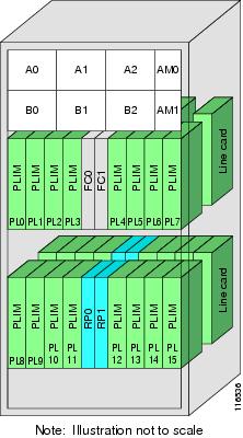
Table 1 summarizes the node-id for each type of card.
|
Card Type (the card to which your are issuing commands) |
Rack (always “0” in a single-shelf system) |
Slot (the physical slot in which the card is installed) |
Module (the entity on the card that is the target of the command) |
|---|---|---|---|
| Route processor |
0–255 |
RP0 and RP1 |
CPU0 |
| DRP |
0-255 |
0–7 (8-slot chassis) 0–15 (16-slot chassis) |
CPU0 or CPU1 |
| MSC |
0–255 |
0-3 (4-slot chassis) 0–7 (8-slot chassis) 0–15 (16-slot chassis) |
Service processor (SP) |
| PLIM |
0–255 |
0-3 (4-slot chassis) 0–7 (8-slot chassis) 0–15 (16-slot chassis) |
CPU0 |
| Cisco CRS-1 SPA Interface Processor (SIP)-800 |
0–255 |
0–7 (8-slot chassis) 0–15 (16-slot chassis) |
CPU0 |
| 1-Port OC-192c/STM-64c Packet-over-SONET/SDH (POS) XFP SPA 4-Port OC-3c/STM-1 POS SPA 8-Port Gigabit Ethernet SPA |
0–255 |
0–7 (8-slot chassis) 0–15 (16-slot chassis) |
0–5 (SPA module number on the Cisco CRS-1 SIP-800) |
| Switch fabric module |
0–255 |
SM0–SM3 (4-slot chassis) SM0–SM3 (8-slot chassis) SM0–SM7 (16-slot chassis) |
SP |
| Alarm cards |
0–255 |
AM0–AM1 (16-slot chassis) |
SP |
| Fan controller cards |
0–255 |
FC0–FC1 (16-slot chassis) |
SP |
Displaying Router Node IDs and Status
In administration EXEC mode, the show platform command displays information for all router nodes, which include nodes in all chassis and SDRs. In administration EXEC mode, the command display also includes additional node IDs such as those for fabric cards, alarm modules, and fan controllers. For each node, this information includes the host card type, the operational state, and the configuration state. To display information on a single node, enter the command with a node ID.
The syntax for the show platform command is:
show platform [node-id]
The following example displays the status for all nodes in a Cisco CRS-1 Multishelf System:
RP/0/RP0/CPU0:router(admin)# show platform

Node            Type            PLIM            State           Config State
-----------------------------------------------------------------------------
0/5/SP          MSC(SP)         N/A             IOS XR RUN      PWR,NSHUT,MON
0/5/CPU0        MSC             4OC192-POS/DPT  IOS XR RUN      PWR,NSHUT,MON
0/7/SP          DRP(SP)         N/A             IOS XR RUN      PWR,NSHUT,MON
0/7/CPU0        DRP(Active)     DRP-ACC         IOS XR RUN      PWR,NSHUT,MON
0/7/CPU1        DRP(Active)     DRP-ACC         IOS XR RUN      PWR,NSHUT,MON
0/14/SP         MSC(SP)         N/A             IOS XR RUN      PWR,NSHUT,MON
0/14/CPU0       MSC             8-10GbE         IOS XR RUN      PWR,NSHUT,MON
0/RP0/CPU0      RP(Active)      N/A             IOS XR RUN      PWR,NSHUT,MON
0/RP1/CPU0      RP(Standby)     N/A             IOS XR RUN      PWR,NSHUT,MON
0/FC0/SP        LCC-FAN-CT(SP)  N/A             IOS XR RUN      PWR,NSHUT,MON
0/FC1/SP        LCC-FAN-CT(SP)  N/A             IOS XR RUN      PWR,NSHUT,MON
0/AM0/SP        ALARM(SP)       N/A             IOS XR RUN      PWR,NSHUT,MON
0/AM1/SP        ALARM(SP)       N/A             IOS XR RUN      PWR,NSHUT,MON
0/SM0/SP        FC/M(SP)        N/A             IOS XR RUN      PWR,NSHUT,MON
0/SM1/SP        FC/M(SP)        N/A             IOS XR RUN      PWR,NSHUT,MON
0/SM2/SP        FC/M(SP)        N/A             IOS XR RUN      PWR,NSHUT,MON
0/SM3/SP        FC/M(SP)        N/A             IOS XR RUN      PWR,NSHUT,MON
0/SM4/SP        FC/M(SP)        N/A             IOS XR RUN      PWR,NSHUT,MON
0/SM5/SP        FC/M(SP)        N/A             IOS XR RUN      PWR,NSHUT,MON
0/SM6/SP        FC/M(SP)        N/A             IOS XR RUN      PWR,NSHUT,MON
0/SM7/SP        FC/M(SP)        N/A             IOS XR RUN      PWR,NSHUT,MON
1/4/SP          MSC(SP)         N/A             IOS XR RUN      PWR,NSHUT,MON
1/4/CPU0        MSC             4OC192-POS/DPT  IOS XR RUN      PWR,NSHUT,MON
1/RP0/CPU0      RP(Active)      N/A             IOS XR RUN      PWR,NSHUT,MON
1/RP1/CPU0      RP(Standby)     N/A             IOS XR RUN      PWR,NSHUT,MON
1/FC0/SP        LCC-FAN-CT(SP)  N/A             IOS XR RUN      PWR,NSHUT,MON
1/FC1/SP        LCC-FAN-CT(SP)  N/A             IOS XR RUN      PWR,NSHUT,MON
1/AM0/SP        ALARM(SP)       N/A             IOS XR RUN      PWR,NSHUT,MON
1/SM0/SP        FC/M(SP)        N/A             IOS XR RUN      PWR,NSHUT,MON
1/SM1/SP        FC/M(SP)        N/A             IOS XR RUN      PWR,NSHUT,MON
1/SM3/SP        FC/M(SP)        N/A             IOS XR RUN      PWR,NSHUT,MON
1/SM4/SP        FC/M(SP)        N/A             IOS XR RUN      PWR,NSHUT,MON
1/SM5/SP        FC/M(SP)        N/A             IOS XR RUN      PWR,NSHUT,MON
1/SM6/SP        FC/M(SP)        N/A             IOS XR RUN      PWR,NSHUT,MON
1/SM7/SP        FC/M(SP)        N/A             IOS XR RUN      PWR,NSHUT,MON
F0/SM4/SP       FCC-SFC(SP)     FCC-FM-1S       IOS XR RUN      PWR,NSHUT,MON
F0/SM5/SP       FCC-SFC(SP)     FCC-FM-1S       IOS XR RUN      PWR,NSHUT,MON
F0/SM6/SP       FCC-SFC(SP)     FCC-FM-1S       IOS XR RUN      PWR,NSHUT,MON
F0/SM7/SP       FCC-SFC(SP)     FCC-FM-1S       IOS XR RUN      PWR,NSHUT,MON
F0/SC0/CPU0     FCC-SC(Active)  N/A             IOS XR RUN      PWR,NSHUT,MON
F0/SC1/CPU0     FCC-SC(Standby) N/A             IOS XR RUN      PWR,NSHUT,MON
F0/AM0/SP       ALARM(SP)       N/A             IOS XR RUN      PWR,NSHUT,MON
F0/AM1/SP       ALARM(SP)       N/A             IOS XR RUN      PWR,NSHUT,MON
F0/LM0/SP       FCC-LED(SP)     N/A             IOS XR RUN      PWR,NSHUT,MON
F0/LM1/SP       UNKNOWN(SP)     N/A             IN-RESET        PWR,NSHUT,MON
Note | Line cards are called modular services cards (MSCs). |
The node-id appears in the rack/slot/module notation, and the node-id components are as follows:
-
rack —In a single-shelf system the rack number is always “0.” In a multishelf system, the LCC rack number range is 0 to 255 and the FCC rack number range is F0 to F7.
-
slot —Number of the physical slot in which the card is installed.
-
module —Subslot number of a system hardware component.
Table 1 summarizes the node-id argument for each type of card.
Displaying Router Environment Information
The show environment command displays hardware information for the system, including fan speeds, LED indications, power supply voltage and current information, and temperatures.
The syntax for the show environment command is:
show environment [options]
You can use the show environment command options to limit the detail in the command display. To view the command options, enter the show environment ? command. The following example shows the full environment status report:
RP/0/RP0/CPU0:router# show environment

  Temperature Information
  ---------------------------------------------

  R/S/I   Modules Sensor          Temp. (deg C)

  0/0/*     host  Inlet              23.0
            host  Hot                23.0
  0/3/*     host  Inlet              24.0
            host  Hot                33.0
  0/4/*     host  Inlet              24.5
            host  Hot                31.5
  0/5/*     host  Inlet              23.5
            host  Hot                30.5
  0/6/*     host  Hot                31.5
            host  Inlet              22.5
  0/7/*     host  Inlet              20.0
            host  Hot                29.5
  0/8/*     host  Inlet              20.5
            host  Hot                32.0

  Threshold Information
  ---------------------------------------------

  R/S/I   Modules Sensor          Minor           Major           Critical
                                  (Lo/Hi)         (Lo/Hi)         (Lo/Hi)

  0/0/*     host  InletTemp        --/  55          --/  60          --/  --
            host  HotTemp          --/  66          --/  69          --/  --
            host  PLIM_V4_1.6V     --/  --          --/  --          --/  --
            host  PLIM_V5_1.8V     --/  --          --/  --          --/  --
            host  PLIM_V3_2.5V     --/  --          --/  --          --/  --
            host  3.4V           2950/3500        2900/3600          --/  --
            host  5V             4800/5150        4700/5200          --/  --
            host  Mbus5V         4700/5300        4500/5500          --/  --
  0/3/*     host  InletTemp        --/  55          --/  60          --/  70
            host  HotTemp          --/  66          --/  69          --/  75
            host  PLIM_V3_1.5V     --/  --          --/  --          --/  --
            host  PLIM_V8_1.8V     --/  --          --/  --          --/  --
            host  PLIM_V7_2.5V     --/  --          --/  --          --/  --
            host  3.4V             --/  --          --/  --          --/  --
            host  5V             4800/5200        4700/5300        4600/5400
            host  Mbus5V         4700/5300        4600/5400        4500/5500
  0/4/*     host  InletTemp        --/  55          --/  60          --/  70
            host  HotTemp          --/  66          --/  69          --/  75
            host  PLIM_V3_1.5V     --/  --          --/  --          --/  --
            host  PLIM_V8_1.8V     --/  --          --/  --          --/  --
            host  PLIM_V7_2.5V     --/  --          --/  --          --/  --
            host  PLIM_V6_1.5V     --/  --          --/  --          --/  --
            host  5V               --/  --          --/  --          --/  --
            host  3.4V             --/  --          --/  --          --/  --
            host  Mbus5V         4700/5300        4600/5400        4500/5500
  0/5/*     host  InletTemp        --/  55          --/  60          --/  70
            host  HotTemp          --/  66          --/  69          --/  75
            host  PLIM_V3_1.5V     --/  --          --/  --          --/  --
            host  PLIM_V8_1.8V     --/  --          --/  --          --/  --
            host  PLIM_V7_2.5V     --/  --          --/  --          --/  --
            host  PLIM_V6_1.5V     --/  --          --/  --          --/  --
            host  5V               --/  --          --/  --          --/  --
            host  3.4V             --/  --          --/  --          --/  --
            host  Mbus5V         4700/5300        4600/5400        4500/5500
  0/6/*     host  HotTemp          --/  66          --/  69          --/  75
            host  InletTemp        --/  55          --/  60          --/  70
            host  PLIM_V3_1.5V     --/  --          --/  --          --/  --
            host  PLIM_V8_1.8V     --/  --          --/  --          --/  --
            host  PLIM_V7_2.5V     --/  --          --/  --          --/  --
            host  3.4V             --/  --          --/  --          --/  --
            host  Mbus5V         4700/5300        4600/5400        4500/5500
  0/7/*     host  InletTemp        --/  55          --/  60          --/  70
            host  HotTemp          --/  66          --/  69          --/  75
            host  PLIM_V3_1.5V     --/  --          --/  --          --/  --
            host  PLIM_V8_1.8V     --/  --          --/  --          --/  --
            host  PLIM_V7_2.5V     --/  --          --/  --          --/  --
            host  PLIM_V6_1.5V     --/  --          --/  --          --/  --
            host  5V               --/  --          --/  --          --/  --
            host  3.4V             --/  --          --/  --          --/  --
            host  Mbus5V         4700/5300        4600/5400        4500/5500
  0/8/*     host  InletTemp        --/  55          --/  60          --/  70
            host  HotTemp          --/  66          --/  69          --/  75
            host  PLIM_V3_1.5V     --/  --          --/  --          --/  --
            host  PLIM_V8_1.8V     --/  --          --/  --          --/  --
            host  PLIM_V7_2.5V     --/  --          --/  --          --/  --
            host  3.4V             --/  --          --/  --          --/  --
            host  5V             4800/5200        4700/5300        4600/5400
            host  Mbus5V         4700/5300        4600/5400        4500/5500
  Voltage Information
  ---------------------------------------------

  R/S/I   Modules Sensor          Voltage (mV)    Margin

  0/0/*     host  PLIM_V4_1.6V     1612           nominal
            host  PLIM_V5_1.8V     1804           nominal
            host  PLIM_V3_2.5V     2504           nominal
            host  3.4V             3296           nominal
            host  5V               5048           nominal
            host  Mbus5V           5048           n/a
  0/3/*     host  PLIM_V3_1.5V     1496           nominal
            host  PLIM_V8_1.8V     1788           nominal
            host  PLIM_V7_2.5V     2492           nominal
            host  3.4V             3284           nominal
            host  5V               5000           nominal
            host  Mbus5V           5024           n/a
  0/4/*     host  PLIM_V3_1.5V     1500           nominal
            host  PLIM_V8_1.8V     1796           nominal
            host  PLIM_V7_2.5V     2488           nominal
            host  PLIM_V6_1.5V     1508           nominal
            host  5V               4976           nominal
            host  3.4V             3288           nominal
            host  Mbus5V           5048           n/a
  0/5/*     host  PLIM_V3_1.5V     1504           nominal
            host  PLIM_V8_1.8V     1792           nominal
            host  PLIM_V7_2.5V     2488           nominal
            host  PLIM_V6_1.5V     1504           nominal
            host  5V               4976           nominal
            host  3.4V             3284           nominal
            host  Mbus5V           4984           n/a
  0/6/*     host  PLIM_V3_1.5V     1496           nominal
            host  PLIM_V8_1.8V     1792           nominal
            host  PLIM_V7_2.5V     2476           nominal
            host  3.4V             3300           nominal
            host  Mbus5V           5016           n/a
  0/7/*     host  PLIM_V3_1.5V     1504           nominal
            host  PLIM_V8_1.8V     1796           nominal
            host  PLIM_V7_2.5V     2484           nominal
            host  PLIM_V6_1.5V     1504           nominal
            host  5V               4976           nominal
            host  3.4V             3276           nominal
            host  Mbus5V           4984           n/a
  0/8/*     host  PLIM_V3_1.5V     1496           nominal
            host  PLIM_V8_1.8V     1792           nominal
            host  PLIM_V7_2.5V     2492           nominal
            host  3.4V             3280           nominal
            host  5V               5000           nominal
            host  Mbus5V           5024           n/a
Displaying RP Redundancy Status
The show redundancy command displays the redundancy status of the route processors (RPs) . This command also displays the boot and switch-over history for the RPs.
The show redundancy operates in EXEC and administration EXEC mode.
In the following example, the show redundancy command displays the redundancy status for a redundant RP pair:
RP/0/RP0/CPU0:router# show redundancy

  This node (0/RP0/CPU0) is in ACTIVE role
  Partner node (0/RP1/CPU0) is in STANDBY role
  Standby node in 0/RP1/CPU0 is ready

  Reload and boot info
  ----------------------
  RP reloaded Fri Apr  9 03:44:28 2004: 16 hours, 51 minutes ago
  This node booted Fri Apr  9 06:19:05 2004: 14 hours, 16 minutes ago
  Last switch-over Fri Apr  9 06:53:18 2004: 13 hours, 42 minutes ago
  Standby node boot Fri Apr  9 06:54:25 2004: 13 hours, 41 minutes ago
  Standby node last not ready Fri Apr  9 20:35:23 2004: 0 minutes ago
  Standby node last ready Fri Apr  9 20:35:23 2004: 0 minutes ago
  There have been 2 switch-overs since reload
Displaying Field-Programmable Device Compatibility
The show hw-module fpd command displays field-programmable device (FPD) compatibility for all modules or a specific module.
The syntax for the show hw-module fpd command is:
show hw-module fpd location {all | node-id}
The show hw-module fpd operates in EXEC and administration EXEC mode.
The following example shows how to display FPD compatibility for all modules in the router:
RP/0/RP0/CPU0:router# show hw-module fpd location all

===================================== ==========================================
                                      Existing Field Programmable Devices
                                      ==========================================
                                        HW                       Current SW Upg/
Location     Card Type                Version Type Subtype Inst   Version   Dng?
============ ======================== ======= ==== ======= ==== =========== ====
0/1/CPU0     CRS1-SIP-800               0.96  lc   fpga    0       2.0      No
--------------------------------------------------------------------------------
0/1/0        SPA-4XOC3-POS              1.0   spa  fpga    0       3.4      No
--------------------------------------------------------------------------------
0/1/5        SPA-8X1GE                  2.2   spa  fpga    5       1.8      No
--------------------------------------------------------------------------------
0/6/CPU0     CRS1-SIP-800               0.96  lc   fpga    0       2.0      No
--------------------------------------------------------------------------------
0/6/0        SPA-4XOC3-POS              1.0   spa  fpga    0       3.4      No
--------------------------------------------------------------------------------
0/6/4        SPA-8XOC3-OC12-POS         1.1   spa  fpga    4       0.5      Yes
--------------------------------------------------------------------------------
0/6/5        SPA-8X1GE                  2.2   spa  fpga    5       1.8      No
--------------------------------------------------------------------------------
NOTES:
1.  One or more FPD needs an upgrade or a downgrade.  This can be accomplished
    using the "admin upgrade hw-module fpd" CLI.
RP/0/RP0/CPU0:router# show hw-module fpd location 0/6/cpu0

Sun Apr 18 03:18:24.903 DST

===================================== ==========================================
                                      Existing Field Programmable Devices
                                      ==========================================
                                        HW                       Current SW Upg/
Location     Card Type                Version Type Subtype Inst   Version   Dng?
============ ======================== ======= ==== ======= ==== =========== ====
0/6/CPU0     CRS1-SIP-800               0.96  lc   fpga1   0       6.00     No
                                              lc   rommonA 0       2.100    No
                                              lc   rommon  0       2.100    No
--------------------------------------------------------------------------------
If the cards in the system do not meet the minimum requirements, the output contains a “NOTES” section that states how to upgrade the FPD image.
RP Redundancy and Switchover
This section describes RP redundancy and switchover commands and issues.
- Establishing RP Redundancy
- Determining the Active RP in a Redundant Pair
- Role of the Standby RP
- Summary of Redundancy Commands
- Automatic Switchover
- RP Redundancy During RP Reload
- Manual Switchover
- Communicating with a Standby RP
Establishing RP Redundancy
Your router has two slots for RPs: RP0 and RP1 (see Figure 1). These slots are configured for redundancy by default, and the redundancy cannot be eliminated. To establish RP redundancy, install RPs into both slots.
Determining the Active RP in a Redundant Pair
During system startup, one RP in each redundant pair becomes the active RP. You can tell which RP is the active RP in the following ways:
- The active RP can be identified by the green Primary LED on the faceplate of the card. The active RP is indicated when the Primary LED is on. The alphanumeric LED display on the RP displays ACTV RP.
-
The slot of the active RP is indicated in the CLI prompt. For example:
RP/0/RP1/CPU0:router#
In this example, the prompt indicates that you are communicating with the active RP in slot RP1. See Cisco IOS XR Getting Started Guide for the Cisco CRS Router for a complete description of the CLI prompt.
-
Enter the show redundancy command in EXEC mode to display a summary of the active and standby RP status. For example:
RP/0/RP0/CPU0:router# show redundancy

  This node (0/RP0/CPU0) is in ACTIVE role
  Partner node (0/RP1/CPU0) is in STANDBY role
  Standby node in 0/RP1/CPU0 is ready

  Reload and boot info
  ----------------------
  RP reloaded Fri Apr  9 03:44:28 2004: 16 hours, 51 minutes ago
  This node booted Fri Apr  9 06:19:05 2004: 14 hours, 16 minutes ago
  Last switch-over Fri Apr  9 06:53:18 2004: 13 hours, 42 minutes ago
  Standby node boot Fri Apr  9 06:54:25 2004: 13 hours, 41 minutes ago
  Standby node last not ready Fri Apr  9 20:35:23 2004: 0 minutes ago
  Standby node last ready Fri Apr  9 20:35:23 2004: 0 minutes ago
  There have been 2 switch-overs since reload
Role of the Standby RP
The second RP to boot in a redundant pair automatically becomes the standby RP. While the active RP manages the system and communicates with the user interface, the standby RP maintains a complete backup of the software and configurations for all cards in the system. If the active RP fails or goes off line for any reason, the standby RP immediately takes control of the system.
Summary of Redundancy Commands
RP redundancy is enabled by default in the Cisco IOS XR software, but you can use the commands described in Table 1 to display the redundancy status of the cards or force a manual switchover.
|
Command |
Description |
|---|---|
|
show redundancy |
Displays the redundancy status of the RPs. This command also displays the boot and switch-over history for the RPs. |
|
redundancy switchover |
Forces a manual switchover to the standby RP. This command works only if the standby RP is installed and in the “ready” state. |
|
show platform |
Displays the status for node, including the redundancy status of the RP cards. In EXEC mode, this command displays status for the nodes assigned to the SDR. In administration EXEC mode, this command displays status for all nodes in the system. |
Automatic Switchover
Automatic switchover from the active RP to the standby RP occurs only if the active RP encounters a serious system error, such as the loss of a mandatory process or a hardware failure. When an automatic switchover occurs, the RPs respond as follows:
RP Redundancy During RP Reload
The reload command causes the active RP to reload the Cisco IOS XR software. When an RP reload occurs, the RPs respond as follows:
- If a standby RP is installed and “ready” for switchover, the standby RP becomes the active RP. The original active RP reboots and becomes the standby RP.
- If the standby RP is not in the “ready” state, then both RPs reboot. The first RP to boot successfully assumes the role of active RP.
 Caution | You should not use the reload command to force an RP switchover because the result could be a significant loss of router operations. Instead, use the redundancy switchover command to fail over to the standby RP, then use the hw-module location node-id reload command to reload the new standby RP. |
Manual Switchover
You can force a manual switchover from the active RP to the standby RP using the redundancy switchover command.
If a standby RP is installed and ready for switchover, the standby RP becomes the active RP. The original active RP becomes the standby RP. In the following example, partial output for a successful redundancy switchover operation is shown:
RP/0/RP0/CPU0:router# show redundancy

  This node (0/RP0/CPU0) is in ACTIVE role
  Partner node (0/RP1/CPU0) is in STANDBY role
  Standby node in 0/RP1/CPU0 is ready

  RP/0/RP0/CPU0:router# redundancy switchover
  Updating Commit Database.  Please wait...[OK]
  Proceed with switchover 0/RP0/CPU0 -> 0/RP1/CPU0? [confirm]
  Initiating switch-over.
  RP/0/RP0/CPU0:router#

  <Your 'TELNET' connection has terminated>
In the preceding example, the Telnet connection is lost when the previously active RP resets. To continue management of the router, you must connect to the newly activated RP as shown in the following example:
User Access Verification

  Username: xxxxx
  Password: xxxxx
  Last switch-over Sat Apr 15 12:26:47 2009: 1 minute ago


RP/0/RP1/CPU0:router#
If the standby RP is not in “ready” state, the switchover operation is not allowed. In the following example, partial output for a failed redundancy switchover attempt is shown:
RP/0/RP0/CPU0:router# show redundancy

  Redundancy information for node 0/RP1/CPU0:
  ==========================================
  Node 0/RP0/CPU0 is in ACTIVE role
  Partner node (0/RP1/CPU0) is in UNKNOWN role

  Reload and boot info
  ----------------------
  RP reloaded Wed Mar 29 17:22:08 2009: 2 weeks, 2 days, 19 hours, 14 minutes ago
  Active node booted Sat Apr 15 12:27:58 2009: 8 minutes ago
  Last switch-over Sat Apr 15 12:35:42 2009: 1 minute ago
  There have been 4 switch-overs since reload

  RP/0/RP0/CPU0:router# redundancy switchover

  Switchover disallowed: Standby node is not ready.
Communicating with a Standby RP
The active RP automatically synchronizes all system software, settings, and configurations with the standby RP.
If you connect to the standby RP through the console port, you can view the status messages for the standby RP. The standby RP does not display a CLI prompt, so you cannot manage the standby card while it is in standby mode.
If you connect to the standby RP through the management Ethernet port, the prompt that appears is for the active RP, and you can manage the router the same as if you had connected through the management Ethernet port on the active RP.
Reloading, Shutting Down, or Power Cycling a Node
Use the commands described in this section to reload the Cisco IOS XR software on the active RP or on any specified node in the system. This section also describes the commands used to administratively shut down a node and power a node on or off.
Table 1 summarizes the commands described in this section.
|
Command |
Description |
||
|---|---|---|---|
|
hw-module location node-id power disable |
This command administratively turns the power off for a node. It is entered in administration configuration mode. The changes do not take effect until you enter the commit command. To power on a node, use the no form of this command.
|
||
|
hw-module location node-id reload |
This command works in EXEC mode and reloads the Cisco IOS XR software on a specific node or all nodes. To specify all nodes, enter the all keyword in place of the node-id argument. The node reloads with the current running configuration and active software set for that node. |
||
|
hw-module shutdown location node-id |
This command must be entered in administration configuration mode and administratively shuts down the specified node. Nodes that are shut down still have power but cannot load or operate Cisco IOS XR software. To return a node to the up state, use the no form of this command.
|
Reloading the Active RP
The reload command causes the active RP to reload the Cisco IOS XR software according to the configuration register setting. This setting determines how the active RP acts when reloaded.
This section contains instructions to reload the Cisco IOS XR software and return to EXEC mode. For instructions to use the reload command for entering ROM Monitor bootstrap mode, see Cisco IOS XR ROM Monitor Guide for the Cisco CRS Router.
Caution | Because the reload command causes the active RP to go off line and either reload the Cisco IOS XR software or enter ROM Monitor mode, the router experiences a loss of service unless a redundant standby RP is installed and in “ready” state. To display the status of the standby RP, use the show redundancy command in EXEC mode. |
1.
show
redundancy
2.
admin
3.
show
variables
boot
4.
(Optional)
config-register
register-value
5.
admin
6.
reload
DETAILED STEPS
| Command or Action | Purpose | |||
|---|---|---|---|---|
| Step 1 |
show
redundancy
Example:
RP/0/RP0/CPU0:router# show redundancy
|
Displays the RP redundancy status. | ||
| Step 2 |
admin
Example:
RP/0/RP0/CPU0:router# admin
|
Enters administration EXEC mode. | ||
| Step 3 |
show
variables
boot
Example:
RP/0/RP0/CPU0:router(admin)# show variables boot
|
Displays the configuration register setting.
| ||
| Step 4 |
config-register
register-value
Example:
RP/0/RP0/CPU0:router(admin)# config-register 0x102
| (Optional)
Sets the configuration register to the respective value. This step is necessary only if the register is not set to the respective value (0x102 or 0x2102) in the running configuration. You can use either 0x102 or 0x2102. Both these values specify the same functionality, as bit 13 in 0x2102 is not significant for Cisco IOS XR software. | ||
| Step 5 |
admin
Example:
RP/0/RP0/CPU0:router# admin
|
Enters administration EXEC mode. | ||
| Step 6 |
reload
Example:
RP/0/RP0/CPU0:router# reload
|
Reloads the active RP according to the configuration register setting.
|
Flash Disk Recovery
When an RP or DRP is power cycled or experiences an ungraceful reset, the boot disk (PCMCIA flash disk used to boot the card) may experience a file-system corruption. If this occurs, an error message is displayed and the RP or DRP fails to boot. The corrupted flash disk is automatically reformatted and the Cisco IOS XR software is restored from the designated system controller (DSC) for the system.
For example, if a flash disk for an RP or DRP is corrupted, the RP or DRP fails to boot and the following error message is displayed:
  #########################################################
                Restricted Rights Legend
  Use, duplication, or disclosure by the Government is
  subject to restrictions as set forth in subparagraph
  (c) of the Commercial Computer Software - Restricted
  Rights clause at FAR sec. 52.227-19 and subparagraph
  (c) (1) (ii) of the Rights in Technical Data and Computer
  Software clause at DFARS sec. 252.227-7013.

             cisco Systems, Inc.
             170 West Tasman Drive
             San Jose, California 95134-1706

  Cisco IOS XR Software for the Cisco XR Cisco CRS Router-mbirp,
  Copyright (c) 2009 by Cisco Systems, Inc.
  Unable to mount /disk0:, filesystem is corrupted.
  Check fsck log at /tmp/chkfs_fd0.log
  init: special_commands:wait for disk0: failed
If this occurs, then the flash disk is automatically reformatted and the Cisco IOS XR software is restored to the flash disk.
Note | If the flash disk is badly damaged and cannot be reformatted, the disk must be replaced. If the corrupted flash disk is the DSC, then the router fails over to the standby DSC. If no standby DSC is installed, then the system fails to boot. |
Using Controller Commands to Manage Hardware Components
The controller , controllers , and show controllers commands are used to manage and display settings for various hardware components, including the switch fabric management, Ethernet control plane, and interface manager. These commands are primarily diagnostic and related to driver-level details. The information available with these commands varies widely and is hardware specific.
For information on the use of these commands, see Cisco IOS XR Interface and Hardware Component Command Reference for the Cisco CRS Router.
Formatting Hard Drives, Flash Drives, and Other Storage Devices
To format a storage device on the router, use the format command in EXEC mode.
Caution | Formatting a storage device deletes all data on that device. |
The following command syntax is used:
format filesystem: [options]
Table 1 describes the format command syntax.
In the following example, the format command is used to format the hard disk:
RP/0/RP0/CPU0:router# format harddisk:
Removing and Replacing Cards
This section describes card replacement issues and procedures.
- Removing Line Cards, MSCs, or PLIMs
- Real Time Power Monitoring
- Removing and Replacing Cisco 16-Slot Line Card Chassis Switch Fabric Cards
- Removing and Replacing 8-Slot Line Card Chassis Switch Fabric Cards
- Removing and Replacing Cisco 4-Slot Line Card Chassis Switch Fabric Cards
Removing Line Cards, MSCs, or PLIMs
Line cards, modular services cards (MSCs), and physical layer interface modules (PLIMs) are designed for online insertion and removal (OIR). The service processing functions are provided on the MSC, and the physical line interface is provided on a separate card that connects the physical lines to the MSC.
The OIR feature allows you to remove and replace cards without removing power to the card or chassis. Removing a card interrupts all traffic passing through the card, but it does not remove the card configuration.
When you remove a card, the configuration remains for all interfaces, but the interfaces do not appear in the output of the show interfaces command. You can view interface configurations by entering the show running-config command. The following example shows how the configuration appears when a card is removed:
RP/0/RP0/CPU0:router# show running-config

  Building configuration...
  hostname router
  router ospf 3269
   area 0
    interface POS0/3/0/0
     cost 20
  !
  interface preconfigure POS0/3/0/0
   ipv4 address 10.10.50.1 255.255.255.0
  !
  interface preconfigure POS0/3/0/1
   description POS0/3/0/1
   shutdown
  !
  interface preconfigure POS0/3/0/2
   description POS0/3/0/2
   shutdown
  !
  interface preconfigure POS0/3/0/3
   description POS0/3/0/3
   shutdown
  !
In this example, the MSC in slot 3 is removed, and the interface configuration for all four interfaces changes to “interface preconfigure.” However, the “router ospf” reference to a slot 3 interface does not change. If you replace a PLIM with another PLIM that uses the same media type and port count, the configuration becomes active on the replacement card.
To remove the configuration for a slot after a card is removed, use the no interface preconfigure command to remove all interface configuration statements for that card in the running configuration. In addition, search the configuration for any references to the removed interfaces, such as the “router ospf” reference to slot 3 in the preceding example.
To remove the configuration for a slot when a card is installed, use the no interface command to remove all interface configuration statements for that card in the running configuration. In addition, search the configuration for any references to the removed interfaces.
Each PLIM supports a specific media type (Packet over SONET/SDH [POS] or Ethernet, for example) and port count. If you replace a PLIM with one that supports a different media type or port count, you should review the configuration and revise it to support the replacement PLIM .
- Replacing an MSC
- Replacing a Line Card or PLIM with the Same Media Type and Port Count
- Replacing a Line Card or PLIM with the Same Media Type and a Different Port Count
- Replacing a Line Card or PLIM with a Different Media Type
Replacing an MSC
When you replace an MSC, the guidelines in the Removing Line Cards, MSCs, or PLIMs apply. Because only one type of MSC exists, no special procedures are required for card removal and replacement.
Replacing a Line Card or PLIM with the Same Media Type and Port Count
When you replace a line card or PLIM with a card that is of the same media type and has the same port count as the replaced card, the guidelines in the Removing Line Cards, MSCs, or PLIMs apply. Because the replacement card is of the same media type and port count, no special procedures are required for card removal and replacement.
Replacing a Line Card or PLIM with the Same Media Type and a Different Port Count
When you replace a line card or PLIM with a card that is of the same media type with a different port count, the guidelines in Removing Line Cards, MSCs, or PLIMs apply.
If the new card has a greater port count than the replaced card, the configuration applies to the corresponding lower port numbers, and the ports that did not exist on the replaced card have no configuration and come up in the shutdown state.
If the new card supports fewer ports, the existing configuration for the corresponding number of ports on the new card set is applied. The previous configuration for the removed ports remains in interface preconfigure state, as shown in the following example:
RP/0/RP0/CPU0:router# show running-config

  Building configuration...
  hostname rtp-gsr1
  interface POS0/3/0/0
   ipv4 address 10.10.50.1 255.255.255.0
  !
  interface preconfigure POS0/3/0/1
   description POS0/3/0/1
   shutdown
  !
  interface preconfigure POS0/3/0/2
   description POS0/3/0/2
   shutdown
  !
  interface preconfigure POS0/3/0/3
   description POS0/3/0/3
   shutdown
  !
In the preceding example, a four-port card has been replaced with a single-port card. The configuration from port 1 on the four-port card is applied to the single port on the replacement card, and the remaining port configurations change to “interface preconfigure.” To remove the configuration for the missing interfaces, use the no interface preconfigure command. In addition, search for and remove any configuration references to the removed interfaces.
Whenever you replace a line card or PLIM with the same media type and a different port count, review the running configuration in the router and revise the configuration as necessary.
Replacing a Line Card or PLIM with a Different Media Type
When you replace a line card or PLIM with a card that is of a different media type (for example, if you replace a POS PLIM with an Ethernet PLIM), the guidelines in Removing Line Cards, MSCs, or PLIMs apply. Review the running configuration in the router and revise the configuration as necessary for the new media type.
Real Time Power Monitoring
Real Time Power monitoring feature consolidates the power consumption values into a common interface. The user can now know the real time power being consumed on the individual slots and the router as a whole.
Advantages
With real time power monitoring, power consumption is maintained at slot level granularity. The user can identify to which power consuming slab the system belongs to, and can take business decisions accordingly.
Card support
Real Time Power is supported on the following cards:
- Cisco CRS Modular Services card 400G
- Cisco CRS Modular Services card 200G
- Cisco CRS Series 16 Slots Fabric Card / Multi (400G)
- Cisco CRS Series 16 Slots Fabric Card / Multi (200G)
- Cisco CRS Series 16 Slots Fabric Card / Single (400G)
- Cisco CRS Series 8 Slots Fabric Card / Single (400G)
- Cisco CRS Series 40x10GE Interface Module
- Cisco CRS Series 4x100GE Interface Module
-
Cisco CRS 2X100GE (CPAK) and 5X40GE (QSFP+) LAN/OTN Flexible Interface Module
Removing and Replacing Cisco 16-Slot Line Card Chassis Switch Fabric Cards
16-slot LCCs support two switch fabric cards: the CRS-16-FC/S and the CRS-16-FC/M. The CRS-16-FC/S switch fabric card provides the Stage 1, 2, and 3 switch fabric for one fabric plane in a standalone Cisco CRS-1 Carrier Routing System 16-Slot Line Card Chassis. The CRS-16-FC/M switch fabric card provides the Stage 1 and 3 switch fabric for one fabric plane in a Cisco CRS-1 LCC within a multishelf system.
The Cisco CRS-1 16-Slot LCC can support the maximum throughput with seven of the eight fabric planes. To prevent traffic loss, we recommend that you shut the power down on a fabric plane for a switch fabric card before you remove it. If a switch fabric card is removed with the power on, the card is not harmed, but some traffic may be lost. When the replacement card is inserted, you can restore the power to the fabric plane and bring up the replacement card. This section describes how to properly remove and replace Cisco CRS-16-FC/S and Cisco CRS-16-FC/M cards for upgrades or repairs.
Note | The process of removing and replacing cards while the router power is on is called online insertion and removal (OIR). This procedure removes power to a specific slot before the switch fabric card is replaced. The power remains on for all other slots. |
Tip | For more information about switch fabric cards, see Related Topics. |
Note | This procedure does not apply when starting the router for the first time or after a power cycle or reload. |
-
You must be in a user group associated with a task group that includes the proper task IDs. The command reference guides include the task IDs required for each command. If you suspect user group assignment is preventing you from using a command, contact your AAA administrator for assistance.
-
You must log in as root-system before starting the procedure. To confirm your login status, use the show user group command:
RP/0/RP0/CPU0:router# show user group

  root-system, cisco-support
To confirm your login status including root, use the show user all | include root command:
RP/0/RP0/CPU0:router# show user all | include root

  Groups: root-system, cisco-support
  Task:              root-lr  : READ    WRITE    EXECUTE    DEBUG (reserved)
  Task:          root-system  : READ    WRITE    EXECUTE    DEBUG (reserved)
1.
admin
2.
show
platform
3.
show
controllers
fabric
plane
all
4.
admin
5.
controllers
fabric
plane
plane_number
shutdown
6.
commit
7.
end
8.
show
controllers
fabric
plane
all
9.
admin
10.
hw-module
power
disable
location
node-id
11.
show
platform
12. When the fabric card state changes to UNPOWERED, replace the fabric card.
13.
admin
14.
no
hw-module
power
disable
location
node-id
15.
show
platform
16.
admin
17.
no
controllers
fabric
plane
plane_number
shutdown
18.
show
controllers
fabric
plane
all
DETAILED STEPS
Examples
The following example shows the commands and command responses for replacing a a 16-slot LCC fabric card:
RP/0/RP1/CPU0:router# admin
RP/0/RP1/CPU0:router(admin)# show platform

  Node            Type            PLIM            State           Config State
  -----------------------------------------------------------------------------
  0/1/SP          MSC(SP)         N/A             IOS XR RUN      PWR,NSHUT,MON
  0/1/CPU0        MSC             16OC48-POS/DPT  IOS XR RUN      PWR,NSHUT,MON
  0/RP1/CPU0      RP(Active)      N/A             IOS XR RUN      PWR,NSHUT,MON
  0/SM0/SP        FC/S(SP)        N/A             IOS XR RUN      PWR,NSHUT,MON
  0/SM1/SP        FC/S(SP)        N/A             IOS XR RUN      PWR,NSHUT,MON
  0/SM2/SP        FC/S(SP)        N/A             IOS XR RUN      PWR,NSHUT,MON
  0/SM3/SP        FC/S(SP)        N/A             IOS XR RUN      PWR,NSHUT,MON
  0/SM4/SP        FC/S(SP)        N/A             IOS XR RUN      PWR,NSHUT,MON
  0/SM5/SP        FC/S(SP)        N/A             IOS XR RUN      PWR,NSHUT,MON
  0/SM6/SP        FC/S(SP)        N/A             IOS XR RUN      PWR,NSHUT,MON
  0/SM7/SP        FC/S(SP)        N/A             IOS XR RUN      PWR,NSHUT,MON

RP/0/RP1/CPU0:router(admin)# show controllers fabric plane all

    Flags: P - plane admin down,       p - plane oper down

           C - card admin down,        c - card  oper down
           L - link port admin down,   l - linkport oper down
           A - asic admin down,        a - asic oper down
           B - bundle port admin Down, b - bundle port oper down
           I - bundle admin down,      i - bundle oper down
           N - node admin down,        n - node down
           o - other end of link down  d - data down
           f - failed component downstream
           m - plane multicast down

   Plane  Admin   Oper

   Id     State   State
   --------------------
   0      UP      UP
   1      UP      UP
   2      UP      UP
   3      UP      UP
   4      UP      UP
   5      UP      UP
   6      UP      UP
   7      UP      UP

RP/0/RP1/CPU0:router(admin)# configure
RP/0/RP1/CPU0:router(admin-config)# controllers fabric plane 0 shutdown
RP/0/RP1/CPU0:router(admin-config)# commit

  RP/0/RP1/CPU0:Oct  5 02:15:09.265 : fsdb_aserver[173]: %FABRIC-FSDB-1-PLANE_UPDO
  WN : Plane 0 state changed to DOWN:
  RP/0/RP1/CPU0:Oct  5 02:15:09.319 : config[65734]: %MGBL-LIBTARCFG-6-ADMIN_COMMI
  T : Administration configuration committed by user 'jim'.

RP/0/RP1/CPU0:router(admin-config)# end
RP/0/RP1/CPU0:router(admin)# show controllers fabric plane all

    Flags: P - plane admin down,       p - plane oper down
           C - card admin down,        c - card  oper down
           L - link port admin down,   l - linkport oper down
           A - asic admin down,        a - asic oper down
           B - bundle port admin Down, b - bundle port oper down
           I - bundle admin down,      i - bundle oper down
           N - node admin down,        n - node down
           o - other end of link down  d - data down
           f - failed component downstream
           m - plane multicast down

   Plane  Admin   Oper
   Id     State   State
   --------------------
   0      DOWN    DOWN
   1      UP      UP
   2      UP      UP
   3      UP      UP
   4      UP      UP
   5      UP      UP
   6      UP      UP
   7      UP      UP

RP/0/RP1/CPU0:router(admin)# configure
RP/0/RP1/CPU0:router(admin-config)# hw-module power disable location 0/SM0/SP
RP/0/RP1/CPU0:router(admin-config)# commit

  RP/0/RP1/CPU0:Oct  5 02:18:24.774 : config[65734]: %MGBL-LIBTARCFG-6-COMMIT : Co
  nfiguration committed by user 'jim'.   Use 'show configuration commit changes 10
  00000142' to view the changes.
  RP/0/RP1/CPU0:router(config)#LC/0/1/CPU0:Oct  5 02:18:26.873 : fabricq_mgr[
  127]: %FABRIC-FABRICQ-3-FI_UNCORR_ERROR : fabricq: Major error in Fabric Interfa
  ce : RS Uncorrectable errors on Fabricq ASIC 0 link 3
  RP/0/RP1/CPU0:Oct  5 02:18:28.959 : shelfmgr[284]: %PLATFORM-SHELFMGR-3-POWERDOW
  N_RESET : Node 0/SM0/SP is powered off due to admin power off request

RP/0/RP1/CPU0:router(admin-config)# end
RP/0/RP1/CPU0:router(admin)# show platform

  Node            Type            PLIM            State           Config State
  -----------------------------------------------------------------------------
  0/1/SP          MSC(SP)         N/A             IOS XR RUN      PWR,NSHUT,MON
  0/1/CPU0        MSC             16OC48-POS/DPT  IOS XR RUN      PWR,NSHUT,MON
  0/RP1/CPU0      RP(Active)      N/A             IOS XR RUN      PWR,NSHUT,MON
  0/SM0/SP        FC/S(SP)        N/A             UNPOWERED       NPWR,NSHUT,MON
  0/SM1/SP        FC/S(SP)        N/A             IOS XR RUN      PWR,NSHUT,MON
  0/SM2/SP        FC/S(SP)        N/A             IOS XR RUN      PWR,NSHUT,MON
  0/SM3/SP        FC/S(SP)        N/A             IOS XR RUN      PWR,NSHUT,MON
  0/SM4/SP        FC/S(SP)        N/A             IOS XR RUN      PWR,NSHUT,MON
  0/SM5/SP        FC/S(SP)        N/A             IOS XR RUN      PWR,NSHUT,MON
  0/SM6/SP        FC/S(SP)        N/A             IOS XR RUN      PWR,NSHUT,MON
  0/SM7/SP        FC/S(SP)        N/A             IOS XR RUN      PWR,NSHUT,MON
When the state of the fabric card changes to UNPOWERED, replace the fabric card.
RP/0/RP1/CPU0:router# configure
RP/0/RP1/CPU0:router(admin-config)# no hw-module power disable location 0/SM0/SP
RP/0/RP1/CPU0:router(admin-config)# commit

  RP/0/RP1/CPU0:Oct  5 02:19:30.472 : config[65734]: %MGBL-LIBTARCFG-6-COMMIT : Co
  nfiguration committed by user 'jim'.   Use 'show configuration commit changes 10
  00000143' to view the changes.
  RP/0/RP1/CPU0:router(config)#RP/0/RP1/CPU0:Oct  5 02:19:42.747 : shelfmgr[2
  84]: %PLATFORM-MBIMGR-7-IMAGE_VALIDATED : 0/SM0/SP: MBI tftp:/hfr-os-mbi-3.4.0/
  sp/mbihfr-sp.vm validated

RP/0/RP1/CPU0:router(admin-config)# end
RP/0/RP1/CPU0:router(admin)# show platform

  Node            Type            PLIM            State           Config State
  -----------------------------------------------------------------------------
  0/1/SP          MSC(SP)         N/A             IOS XR RUN      PWR,NSHUT,MON
  0/1/CPU0        MSC             16OC48-POS/DPT  IOS XR RUN      PWR,NSHUT,MON
  0/RP1/CPU0      RP(Active)      N/A             IOS XR RUN      PWR,NSHUT,MON
  0/SM0/SP        FC/S(SP)        N/A             MBI-BOOTING     PWR,NSHUT,MON
  0/SM1/SP        FC/S(SP)        N/A             IOS XR RUN      PWR,NSHUT,MON
  0/SM2/SP        FC/S(SP)        N/A             IOS XR RUN      PWR,NSHUT,MON
  0/SM3/SP        FC/S(SP)        N/A             IOS XR RUN      PWR,NSHUT,MON
  0/SM4/SP        FC/S(SP)        N/A             IOS XR RUN      PWR,NSHUT,MON
  0/SM5/SP        FC/S(SP)        N/A             IOS XR RUN      PWR,NSHUT,MON
  0/SM6/SP        FC/S(SP)        N/A             IOS XR RUN      PWR,NSHUT,MON
  0/SM7/SP        FC/S(SP)        N/A             IOS XR RUN      PWR,NSHUT,MON

RP/0/RP1/CPU0:router(admin)# show platform

  Node            Type            PLIM            State           Config State
  -----------------------------------------------------------------------------
  0/1/SP          MSC(SP)         N/A             IOS XR RUN      PWR,NSHUT,MON
  0/1/CPU0        MSC             16OC48-POS/DPT  IOS XR RUN      PWR,NSHUT,MON
  0/RP1/CPU0      RP(Active)      N/A             IOS XR RUN      PWR,NSHUT,MON
  0/SM0/SP        FC/S(SP)        N/A             MBI-RUNNING     PWR,NSHUT,MON
  0/SM1/SP        FC/S(SP)        N/A             IOS XR RUN      PWR,NSHUT,MON
  0/SM2/SP        FC/S(SP)        N/A             IOS XR RUN      PWR,NSHUT,MON
  0/SM3/SP        FC/S(SP)        N/A             IOS XR RUN      PWR,NSHUT,MON
  0/SM4/SP        FC/S(SP)        N/A             IOS XR RUN      PWR,NSHUT,MON
  0/SM5/SP        FC/S(SP)        N/A             IOS XR RUN      PWR,NSHUT,MON
  0/SM6/SP        FC/S(SP)        N/A             IOS XR RUN      PWR,NSHUT,MON
  0/SM7/SP        FC/S(SP)        N/A             IOS XR RUN      PWR,NSHUT,MON

RP/0/RP1/CPU0:router(admin)# show platform

  Node            Type            PLIM            State           Config State
  -----------------------------------------------------------------------------
  0/1/SP          MSC(SP)         N/A             IOS XR RUN      PWR,NSHUT,MON
  0/1/CPU0        MSC             16OC48-POS/DPT  IOS XR RUN      PWR,NSHUT,MON
  0/RP1/CPU0      RP(Active)      N/A             IOS XR RUN      PWR,NSHUT,MON
  0/SM0/SP        FC/S(SP)        N/A             IOS XR RUN      PWR,NSHUT,MON
  0/SM1/SP        FC/S(SP)        N/A             IOS XR RUN      PWR,NSHUT,MON
  0/SM2/SP        FC/S(SP)        N/A             IOS XR RUN      PWR,NSHUT,MON
  0/SM3/SP        FC/S(SP)        N/A             IOS XR RUN      PWR,NSHUT,MON
  0/SM4/SP        FC/S(SP)        N/A             IOS XR RUN      PWR,NSHUT,MON
  0/SM5/SP        FC/S(SP)        N/A             IOS XR RUN      PWR,NSHUT,MON
  0/SM6/SP        FC/S(SP)        N/A             IOS XR RUN      PWR,NSHUT,MON
  0/SM7/SP        FC/S(SP)        N/A             IOS XR RUN      PWR,NSHUT,MON

RP/0/RP1/CPU0:router(admin)# configure

  SP/0/SM0/SP:Oct  5 02:20:19.102 : init[65541]: %OS-INIT-7-MBI_STARTED : total time
  7.678 seconds
  SP/0/SM0/SP:Oct  5 02:20:21.361 : insthelper[60]: %INSTALL-INSTHELPER-7-PKG_DOWN
  LOAD : MBI running; starting software download
  SP/0/SM0/SP:Oct  5 02:22:23.458 : init[65541]: %OS-INIT-7-INSTALL_READY : total
  time 132.060 seconds
  SP/0/SM0/SP:Oct  5 02:22:39.329 : sfe_drvr[108][120]: Board revision : 0x06.
  SP/0/SM0/SP:Oct  5 02:22:47.306 : sfe_drvr[108]: %FABRIC-FABRIC_DRVR-6-ASIC_IN
  ITIALIZED : Fabric ASICs initialized
  SP/0/SM0/SP:Oct  5 02:23:06.316 : alphadisplay[100]: %PLATFORM-ALPHA_DISPLAY-6-CHANGE :
  Alpha display on node 0/SM0/SP changed to IOS-XR   in state default

RP/0/RP1/CPU0:router(admin-config)# no controllers fabric plane 0 shutdown
RP/0/RP1/CPU0:router(admin-config)# commit

  RP/0/RP1/CPU0:Oct  5 02:25:15.736 : fsdb_aserver[173]: %FABRIC-FSDB-1-PLANE_UPDO
  WN : Plane 0 state changed to UP:
  RP/0/RP1/CPU0:Oct  5 02:25:15.759 : config[65734]: %MGBL-LIBTARCFG-6-ADMIN_COMMI
  T : Administration configuration committed by user 'jim'.

RP/0/RP1/CPU0:router(admin-config)# end
RP/0/RP1/CPU0:router(admin)# show controllers fabric plane all

    Flags: P - plane admin down,       p - plane oper down
           C - card admin down,        c - card  oper down

           L - link port admin down,   l - linkport oper down
           A - asic admin down,        a - asic oper down
           B - bundle port admin Down, b - bundle port oper down
           I - bundle admin down,      i - bundle oper down
           N - node admin down,        n - node down
           o - other end of link down  d - data down
           f - failed component downstream
           m - plane multicast down

   Plane  Admin   Oper
   Id     State   State
   --------------------
   0      UP      UP
   1      UP      UP
   2      UP      UP
   3      UP      UP
   4      UP      UP
   5      UP      UP
   6      UP      UP
   7      UP      UP
Removing and Replacing 8-Slot Line Card Chassis Switch Fabric Cards
Each CRS-8-FC/S switch fabric card provides the Stage 1, 2, and 3 switch fabric for two fabric planes in a Cisco CRS-1 8-Slot Line Card Chassis.
The 8-Slot LCC can support the maximum throughput with seven of the eight fabric planes. However, because each CRS-8-FC/S switch fabric card hosts two fabric planes, replacing a fabric card does reduce the maximum throughput and impacts router traffic if the router is operating at maximum capacity. To minimize traffic loss, we recommend that you shut the power down for the switch fabric card before you remove it. If a switch fabric card is removed with power on, the card is not harmed, but the traffic impact may be greater than if the card power were removed. When the replacement card is inserted, you can restore the power and bring up the replacement card. This section describes how to properly remove and replace a Cisco CRS-8-FC/S switch fabric card for upgrades or repairs.
The process of removing and replacing cards while the router power is on is called online insertion and removal (OIR). This procedure removes power to a specific slot before the switch fabric card is replaced. The power remains on for all other slots.
For more information about switch fabric cards, see Related Topics.
Note | This procedure does not apply when starting the router for the first time or after a power cycle or reload. |
-
You must be in a user group associated with a task group that includes the proper task IDs. The command reference guides include the task IDs required for each command. If you suspect user group assignment is preventing you from using a command, contact your AAA administrator for assistance.
-
You must log in as root-system before starting the procedure. To confirm your login status, use the show user group command:
RP/0/RP0/CPU0:router# show user group

  root-system, cisco-support
To confirm your login status including root, use the show user all | include root command:
RP/0/RP0/CPU0:router# show user all | include root

  Groups: root-system, cisco-support
  Task:              root-lr  : READ    WRITE    EXECUTE    DEBUG (reserved)
  Task:          root-system  : READ    WRITE    EXECUTE    DEBUG (reserved)
1.
admin
2.
show
platform
3.
show
controllers
fabric
plane
all
4.
admin
5.
controllers
fabric
plane
plane_number
shutdown
6.
controllers
fabric
plane
plane_number
shutdown
7.
commit
8.
end
9.
show
controllers
fabric
plane
all
10.
admin
11.
hw-module
power
disable
location
node-id
12.
commit
13.
end
14.
show
platform
15. When the fabric card state changes to UNPOWERED, replace the fabric card.
16.
admin
17.
no
hw-module
power
disable
location
node-id
18.
commit
19.
end
20.
show
platform
21.
admin
22.
no
controllers
fabric
plane
plane_number
shutdown
23.
no
controllers
fabric
plane
plane_number
shutdown
24.
commit
25.
end
26.
show
controllers
fabric
plane
all
DETAILED STEPS
Examples
The following example shows the commands and command responses for replacing an 8-slot LCC fabric card:
RP/0/RP1/CPU0:router# admin
RP/0/RP1/CPU0:router(admin)# show platform

  Node            Type            PLIM            State           Config State
  -----------------------------------------------------------------------------
  0/1/SP          MSC(SP)         N/A             IOS XR RUN      PWR,NSHUT,MON
  0/1/CPU0        MSC             16OC48-POS/DPT  IOS XR RUN      PWR,NSHUT,MON
  0/RP1/CPU0      RP(Active)      N/A             IOS XR RUN      PWR,NSHUT,MON
  0/SM0/SP        FC/S(SP)        N/A             IOS XR RUN      PWR,NSHUT,MON
  0/SM1/SP        FC/S(SP)        N/A             IOS XR RUN      PWR,NSHUT,MON
  0/SM2/SP        FC/S(SP)        N/A             IOS XR RUN      PWR,NSHUT,MON
  0/SM3/SP        FC/S(SP)        N/A             IOS XR RUN      PWR,NSHUT,MON


RP/0/RP1/CPU0:router(admin)# show controllers fabric plane all

  Flags: P - plane admin down,       p - plane oper down

         C - card admin down,        c - card  oper down
         L - link port admin down,   l - linkport oper down
         A - asic admin down,        a - asic oper down
         B - bundle port admin Down, b - bundle port oper down
         I - bundle admin down,      i - bundle oper down
         N - node admin down,        n - node down
         o - other end of link down  d - data down
         f - failed component downstream
         m - plane multicast down

   Plane  Admin   Oper

   Id     State   State
   --------------------
   0      UP      UP
   1      UP      UP
   2      UP      UP
   3      UP      UP
   4      UP      UP
   5      UP      UP
   6      UP      UP
   7      UP      UP

RP/0/RP1/CPU0:router(admin)# configure
RP/0/RP1/CPU0:router(admin-config)# controllers fabric plane 0 shutdown
RP/0/RP1/CPU0:router(admin-config)# controllers fabric plane 1 shutdown
RP/0/RP1/CPU0:router(admin-config)# commit

  RP/0/RP1/CPU0:Oct  5 02:15:09.265 : fsdb_aserver[173]: %FABRIC-FSDB-1-PLANE_UPDO
  WN : Plane 0 state changed to DOWN:
  RP/0/RP1/CPU0:Oct  5 02:15:09.265 : fsdb_aserver[173]: %FABRIC-FSDB-1-PLANE_UPDO
  WN : Plane 1 state changed to DOWN:
  RP/0/RP1/CPU0:Oct  5 02:15:09.319 : config[65734]: %MGBL-LIBTARCFG-6-ADMIN_COMMI
  T : Administration configuration committed by user 'jim'.

RP/0/RP1/CPU0:router(admin-config)# end
RP/0/RP1/CPU0:router(admin)# show controllers fabric plane all

  Flags: P - plane admin down,       p - plane oper down
         C - card admin down,        c - card  oper down
         L - link port admin down,   l - linkport oper down
         A - asic admin down,        a - asic oper down
         B - bundle port admin Down, b - bundle port oper down
         I - bundle admin down,      i - bundle oper down
         N - node admin down,        n - node down
         o - other end of link down  d - data down
         f - failed component downstream
         m - plane multicast down

   Plane  Admin   Oper
   Id     State   State
   --------------------
   0      DOWN    DOWN
   1      DOWN    DOWN
   2      UP      UP
   3      UP      UP
   4      UP      UP
   5      UP      UP
   6      UP      UP
   7      UP      UP

RP/0/RP1/CPU0:router(admin)# configure
RP/0/RP1/CPU0:router(admin-config)# hw-module power disable location 0/SM0/SP
RP/0/RP1/CPU0:router(admin-config)# commit

  RP/0/RP1/CPU0:Oct  5 02:18:24.774 : config[65734]: %MGBL-LIBTARCFG-6-COMMIT : Co
  nfiguration committed by user 'jim'.   Use 'show configuration commit changes 10
  00000142' to view the changes.
  RP/0/RP1/CPU0:router(config)#LC/0/1/CPU0:Oct  5 02:18:26.873 : fabricq_mgr[
  127]: %FABRIC-FABRICQ-3-FI_UNCORR_ERROR : fabricq: Major error in Fabric Interfa
  ce : RS Uncorrectable errors on Fabricq ASIC 0 link 3
  RP/0/RP1/CPU0:Oct  5 02:18:28.959 : shelfmgr[284]: %PLATFORM-SHELFMGR-3-POWERDOW
  N_RESET : Node 0/SM0/SP is powered off due to admin power off request

RP/0/RP1/CPU0:router(admin-config)# end
RP/0/RP1/CPU0:router(admin)# show platform

  Node            Type            PLIM            State           Config State
  -----------------------------------------------------------------------------
  0/1/SP          MSC(SP)         N/A             IOS XR RUN      PWR,NSHUT,MON
  0/1/CPU0        MSC             16OC48-POS/DPT  IOS XR RUN      PWR,NSHUT,MON
  0/RP1/CPU0      RP(Active)      N/A             IOS XR RUN      PWR,NSHUT,MON
  0/SM0/SP        FC/S(SP)        N/A             UNPOWERED       NPWR,NSHUT,MON
  0/SM1/SP        FC/S(SP)        N/A             IOS XR RUN      PWR,NSHUT,MON
  0/SM2/SP        FC/S(SP)        N/A             IOS XR RUN      PWR,NSHUT,MON
  0/SM3/SP        FC/S(SP)        N/A             IOS XR RUN      PWR,NSHUT,MON
When the state for the fabric card changes to UNPOWERED, replace the fabric card.
RP/0/RP1/CPU0:router(admin)# configure
RP/0/RP1/CPU0:router(admin-config)# no hw-module power disable location 0/SM0/SP
RP/0/RP1/CPU0:router(admin-config)# commit

  RP/0/RP1/CPU0:Oct  5 02:19:30.472 : config[65734]: %MGBL-LIBTARCFG-6-COMMIT : Co
  nfiguration committed by user 'jim'.   Use 'show configuration commit changes 10
  00000143' to view the changes.
  RP/0/RP1/CPU0:router(config)#RP/0/RP1/CPU0:Oct  5 02:19:42.747 : shelfmgr[2
  84]: %PLATFORM-MBIMGR-7-IMAGE_VALIDATED : 0/SM0/SP: MBI tftp:/hfr-os-mbi-3.4.0/
  sp/mbihfr-sp.vm validated

RP/0/RP1/CPU0:router(admin-config)# end
RP/0/RP1/CPU0:router(admin)# show platform

  Node            Type            PLIM            State           Config State
  -----------------------------------------------------------------------------
  0/1/SP          MSC(SP)         N/A             IOS XR RUN      PWR,NSHUT,MON
  0/1/CPU0        MSC             16OC48-POS/DPT  IOS XR RUN      PWR,NSHUT,MON
  0/RP1/CPU0      RP(Active)      N/A             IOS XR RUN      PWR,NSHUT,MON
  0/SM0/SP        FC/S(SP)        N/A             MBI-BOOTING     PWR,NSHUT,MON
  0/SM1/SP        FC/S(SP)        N/A             IOS XR RUN      PWR,NSHUT,MON
  0/SM2/SP        FC/S(SP)        N/A             IOS XR RUN      PWR,NSHUT,MON
  0/SM3/SP        FC/S(SP)        N/A             IOS XR RUN      PWR,NSHUT,MON

RP/0/RP1/CPU0:router(admin)# show platform

  Node            Type            PLIM            State           Config State
  -----------------------------------------------------------------------------
  0/1/SP          MSC(SP)         N/A             IOS XR RUN      PWR,NSHUT,MON
  0/1/CPU0        MSC             16OC48-POS/DPT  IOS XR RUN      PWR,NSHUT,MON
  0/RP1/CPU0      RP(Active)      N/A             IOS XR RUN      PWR,NSHUT,MON
  0/SM0/SP        FC/S(SP)        N/A             MBI-RUNNING     PWR,NSHUT,MON
  0/SM1/SP        FC/S(SP)        N/A             IOS XR RUN      PWR,NSHUT,MON
  0/SM2/SP        FC/S(SP)        N/A             IOS XR RUN      PWR,NSHUT,MON
  0/SM3/SP        FC/S(SP)        N/A             IOS XR RUN      PWR,NSHUT,MON


RP/0/RP1/CPU0:router(admin)# show platform

  Node            Type            PLIM            State           Config State
  -----------------------------------------------------------------------------
  0/1/SP          MSC(SP)         N/A             IOS XR RUN      PWR,NSHUT,MON
  0/1/CPU0        MSC             16OC48-POS/DPT  IOS XR RUN      PWR,NSHUT,MON
  0/RP1/CPU0      RP(Active)      N/A             IOS XR RUN      PWR,NSHUT,MON
  0/SM0/SP        FC/S(SP)        N/A             IOS XR RUN      PWR,NSHUT,MON
  0/SM1/SP        FC/S(SP)        N/A             IOS XR RUN      PWR,NSHUT,MON
  0/SM2/SP        FC/S(SP)        N/A             IOS XR RUN      PWR,NSHUT,MON
  0/SM3/SP        FC/S(SP)        N/A             IOS XR RUN      PWR,NSHUT,MON

RP/0/RP1/CPU0:router(admin)# configure

  RP/0/RP1/CPU0:router(admin-config)#SP/0/SM0/SP:Oct  5 02:20:19.102 : init[6
  5541]: %OS-INIT-7-MBI_STARTED : total time 7.678 seconds
  SP/0/SM0/SP:Oct  5 02:20:21.361 : insthelper[60]: %INSTALL-INSTHELPER-7-PKG_DOWN
  LOAD : MBI running; starting software download
  SP/0/SM0/SP:Oct  5 02:22:23.458 : init[65541]: %OS-INIT-7-INSTALL_READY : total
  time 132.060 seconds
  SP/0/SM0/SP:Oct  5 02:22:39.329 : sfe_drvr[108][120]: Board revision : 0x06.
  SP/0/SM0/SP:Oct  5 02:22:47.306 : sfe_drvr[108]: %FABRIC-FABRIC_DRVR-6-ASIC_IN
  ITIALIZED : Fabric ASICs initialized
  SP/0/SM0/SP:Oct  5 02:23:06.316 : alphadisplay[100]: %PLATFORM-ALPHA_DISPLAY-6-CHANGE :
  Alpha display on node 0/SM0/SP changed to IOS-XR   in state default

RP/0/RP1/CPU0:router(admin-config)# no controllers fabric plane 0 shutdown
RP/0/RP1/CPU0:router(admin-config)# no controllers fabric plane 1 shutdown
RP/0/RP1/CPU0:router(admin-config)# commit

  RP/0/RP1/CPU0:Oct  5 02:25:15.736 : fsdb_aserver[173]: %FABRIC-FSDB-1-PLANE_UPDO
  WN : Plane 0 state changed to UP:
  RP/0/RP1/CPU0:Oct  5 02:25:15.736 : fsdb_aserver[173]: %FABRIC-FSDB-1-PLANE_UPDO
  WN : Plane 1 state changed to UP:
  RP/0/RP1/CPU0:Oct  5 02:25:15.759 : config[65734]: %MGBL-LIBTARCFG-6-ADMIN_COMMI
  T : Administration configuration committed by user 'jim'.

RP/0/RP1/CPU0:router(admin-config)# end

  RP/0/RP1/CPU0:Oct  5 02:25:41.891 : config[65734]: %MGBL-SYS-5-CONFIG_I : Config
  ured from console by jim

RP/0/RP1/CPU0:router(admin)# show controllers fabric plane all

  Flags: P - plane admin down,       p - plane oper down
         C - card admin down,        c - card  oper down

         L - link port admin down,   l - linkport oper down
         A - asic admin down,        a - asic oper down
         B - bundle port admin Down, b - bundle port oper down
         I - bundle admin down,      i - bundle oper down
         N - node admin down,        n - node down
         o - other end of link down  d - data down
         f - failed component downstream
         m - plane multicast down

   Plane  Admin   Oper
   Id     State   State
   --------------------
   0      UP      UP
   1      UP      UP
   2      UP      UP
   3      UP      UP
   4      UP      UP
   5      UP      UP
   6      UP      UP
   7      UP      UP
Removing and Replacing Cisco 4-Slot Line Card Chassis Switch Fabric Cards
The Cisco CRS-4-FC switch fabric card provides the Stage 1, 2, and 3 switch fabric for one fabric plane in a Cisco CRS-1 4-Slot Line Card Chassis.
The Cisco CRS-1 4-Slot LCC can support the maximum throughput with three of the four fabric planes. To prevent traffic loss, we recommend that you shut the power down on a fabric plane for a switch fabric card before you remove it. If a switch fabric card is removed with the power on, the card is not harmed, but some traffic may be lost. When the replacement card is inserted, you can restore the power to the fabric plane and bring up the replacement card. This section describes how to properly remove and replace Cisco CRS-4-FC switch fabric cards for upgrades or repairs.
Note | At least two planes of the switch fabric (an even plane and an odd plane) must be active at all times for the Cisco CRS-1 4-slot line card chassis to operate. Otherwise, the switch fabric fails, causing a system failure. The process of removing and replacing cards while the router power is on is called online insertion and removal (OIR). This procedure removes power to a specific slot before the switch fabric card is replaced. The power remains on for all other slots. For more information about switch fabric cards, see the hardware documentation listed in the Related Documents. |
Note | This procedure does not apply when starting the router for the first time or after a power cycle or reload. |
-
You must be in a user group associated with a task group that includes the proper task IDs. The command reference guides include the task IDs required for each command. If you suspect user group assignment is preventing you from using a command, contact your AAA administrator for assistance.
-
You must log in as root-system before starting the procedure. To confirm your login status, use the show user group command:
RP/0/RP0/CPU0:router# show user group

  root-system, cisco-support
To confirm your login status including root, use the show user all | include root command:
RP/0/RP0/CPU0:router# show user all | include root

  Groups: root-system, cisco-support
  Task:              root-lr  : READ    WRITE    EXECUTE    DEBUG (reserved)
  Task:          root-system  : READ    WRITE    EXECUTE    DEBUG (reserved)
1.
admin
2.
show
platform
3.
show
controllers
fabric
plane
all
4.
configure
5.
controllers
fabric
plane
plane_number
shutdown
6.
commit
7.
end
8.
show
controllers
fabric
plane
all
9.
configure
10.
hw-module
power
disable
location
node-id
11.
commit
12.
end
13.
show
platform
14. When the fabric card state changes to UNPOWERED, replace the fabric card.
15.
configure
16.
no
hw-module
power
disable
location
node-id
17.
commit
18.
end
19.
show
platform
20.
configure
21.
no
controllers
fabric
plane
plane_number
shutdown
22.
commit
23.
end
24.
show
controllers
fabric
plane
all
DETAILED STEPS
Examples
The following example shows the commands and command responses for replacing a 4-slot LCC switch fabric card:
RP/0/RP1/CPU0:router# admin
RP/0/RP1/CPU0:router(admin)# show platform


  Node            Type            PLIM            State           Config State
  -----------------------------------------------------------------------------
  0/1/SP          MSC(SP)         N/A             IOS XR RUN      PWR,NSHUT,MON
  0/1/CPU0        MSC             16OC48-POS/DPT  IOS XR RUN      PWR,NSHUT,MON
  0/RP1/CPU0      RP(Active)      N/A             IOS XR RUN      PWR,NSHUT,MON
  0/SM0/SP        FC/S(SP)        N/A             IOS XR RUN      PWR,NSHUT,MON
  0/SM1/SP        FC/S(SP)        N/A             IOS XR RUN      PWR,NSHUT,MON
  0/SM2/SP        FC/S(SP)        N/A             IOS XR RUN      PWR,NSHUT,MON
  0/SM3/SP        FC/S(SP)        N/A             IOS XR RUN      PWR,NSHUT,MON

RP/0/RP1/CPU0:router(admin)# show controllers fabric plane all

    Flags: P - plane admin down,       p - plane oper down

           C - card admin down,        c - card  oper down
           L - link port admin down,   l - linkport oper down
           A - asic admin down,        a - asic oper down
           B - bundle port admin Down, b - bundle port oper down
           I - bundle admin down,      i - bundle oper down
           N - node admin down,        n - node down
           o - other end of link down  d - data down
           f - failed component downstream
           m - plane multicast down

   Plane  Admin   Oper

   Id     State   State
   --------------------
   0      UP      UP
   1      UP      UP
   2      UP      UP
   3      UP      UP

RP/0/RP1/CPU0:router(admin)# configure
RP/0/RP1/CPU0:router(admin-config)# controllers fabric plane 0 shutdown
RP/0/RP1/CPU0:router(admin-config)# commit

  RP/0/RP1/CPU0:Oct  5 02:15:09.265 : fsdb_aserver[173]: %FABRIC-FSDB-1-PLANE_UPDO
  WN : Plane 0 state changed to DOWN:
  RP/0/RP1/CPU0:Oct  5 02:15:09.319 : config[65734]: %MGBL-LIBTARCFG-6-ADMIN_COMMI
  T : Administration configuration committed by user 'jim'.

RP/0/RP1/CPU0:router(admin-config)# end
RP/0/RP1/CPU0:router(admin)# show controllers fabric plane all

    Flags: P - plane admin down,       p - plane oper down
           C - card admin down,        c - card  oper down
           L - link port admin down,   l - linkport oper down
           A - asic admin down,        a - asic oper down
           B - bundle port admin Down, b - bundle port oper down
           I - bundle admin down,      i - bundle oper down
           N - node admin down,        n - node down
           o - other end of link down  d - data down
           f - failed component downstream
           m - plane multicast down

   Plane  Admin   Oper
   Id     State   State
   --------------------
   0      DOWN    DOWN
   1      UP      UP
   2      UP      UP
   3      UP      UP

RP/0/RP1/CPU0:router(admin)# configure
RP/0/RP1/CPU0:router(admin-config)# hw-module power disable location 0/SM0/SP
RP/0/RP1/CPU0:router(admin-config)# commit

  RP/0/RP1/CPU0:Oct  5 02:18:24.774 : config[65734]: %MGBL-LIBTARCFG-6-COMMIT : Co
  nfiguration committed by user 'jim'.   Use 'show configuration commit changes 10
  00000142' to view the changes.
  RP/0/RP1/CPU0:router(config)#LC/0/1/CPU0:Oct  5 02:18:26.873 : fabricq_mgr[
  127]: %FABRIC-FABRICQ-3-FI_UNCORR_ERROR : fabricq: Major error in Fabric Interfa
  ce : RS Uncorrectable errors on Fabricq ASIC 0 link 3
  RP/0/RP1/CPU0:Oct  5 02:18:28.959 : shelfmgr[284]: %PLATFORM-SHELFMGR-3-POWERDOW
  N_RESET : Node 0/SM0/SP is powered off due to admin power off request

RP/0/RP1/CPU0:router(admin-config)# end
RP/0/RP1/CPU0:router(admin)# show platform


  Node            Type            PLIM            State           Config State
  -----------------------------------------------------------------------------
  0/1/SP          MSC(SP)         N/A             IOS XR RUN      PWR,NSHUT,MON
  0/1/CPU0        MSC             16OC48-POS/DPT  IOS XR RUN      PWR,NSHUT,MON
  0/RP1/CPU0      RP(Active)      N/A             IOS XR RUN      PWR,NSHUT,MON
  0/SM0/SP        FC/S(SP)        N/A             UNPOWERED       NPWR,NSHUT,MON
  0/SM1/SP        FC/S(SP)        N/A             IOS XR RUN      PWR,NSHUT,MON
  0/SM2/SP        FC/S(SP)        N/A             IOS XR RUN      PWR,NSHUT,MON
  0/SM3/SP        FC/S(SP)        N/A             IOS XR RUN      PWR,NSHUT,MON
When the state of the fabric card changes to UNPOWERED, replace the fabric card.
RP/0/RP1/CPU0:router# configure
RP/0/RP1/CPU0:router(admin-config)# no hw-module power disable location 0/SM0/SP
RP/0/RP1/CPU0:router(admin-config)# commit

  RP/0/RP1/CPU0:Oct  5 02:19:30.472 : config[65734]: %MGBL-LIBTARCFG-6-COMMIT : Co
  nfiguration committed by user 'jim'.   Use 'show configuration commit changes 10
  00000143' to view the changes.
  RP/0/RP1/CPU0:router(config)#RP/0/RP1/CPU0:Oct  5 02:19:42.747 : shelfmgr[2
  84]: %PLATFORM-MBIMGR-7-IMAGE_VALIDATED : 0/SM0/SP: MBI tftp:/hfr-os-mbi-3.4.0/
  sp/mbihfr-sp.vm validated

RP/0/RP1/CPU0:router(admin-config)# end
RP/0/RP1/CPU0:router(admin)# show platform


  Node            Type            PLIM            State           Config State
  -----------------------------------------------------------------------------
  0/1/SP          MSC(SP)         N/A             IOS XR RUN      PWR,NSHUT,MON
  0/1/CPU0        MSC             16OC48-POS/DPT  IOS XR RUN      PWR,NSHUT,MON
  0/RP1/CPU0      RP(Active)      N/A             IOS XR RUN      PWR,NSHUT,MON
  0/SM0/SP        FC/S(SP)        N/A             MBI-BOOTING     PWR,NSHUT,MON
  0/SM1/SP        FC/S(SP)        N/A             IOS XR RUN      PWR,NSHUT,MON
  0/SM2/SP        FC/S(SP)        N/A             IOS XR RUN      PWR,NSHUT,MON
  0/SM3/SP        FC/S(SP)        N/A             IOS XR RUN      PWR,NSHUT,MON

  RP/0/RP1/CPU0:router(admin)# show platform


 Node            Type            PLIM            State           Config State
  -----------------------------------------------------------------------------
  0/1/SP          MSC(SP)         N/A             IOS XR RUN      PWR,NSHUT,MON
  0/1/CPU0        MSC             16OC48-POS/DPT  IOS XR RUN      PWR,NSHUT,MON
  0/RP1/CPU0      RP(Active)      N/A             IOS XR RUN      PWR,NSHUT,MON
  0/SM0/SP        FC/S(SP)        N/A             MBI-RUNNING     PWR,NSHUT,MON
  0/SM1/SP        FC/S(SP)        N/A             IOS XR RUN      PWR,NSHUT,MON
  0/SM2/SP        FC/S(SP)        N/A             IOS XR RUN      PWR,NSHUT,MON
  0/SM3/SP        FC/S(SP)        N/A             IOS XR RUN      PWR,NSHUT,MON

RP/0/RP1/CPU0:router(admin)# show platform


  Node            Type            PLIM            State           Config State
  -----------------------------------------------------------------------------
  0/1/SP          MSC(SP)         N/A             IOS XR RUN      PWR,NSHUT,MON
  0/1/CPU0        MSC             16OC48-POS/DPT  IOS XR RUN      PWR,NSHUT,MON
  0/RP1/CPU0      RP(Active)      N/A             IOS XR RUN      PWR,NSHUT,MON
  0/SM0/SP        FC/S(SP)        N/A             IOS XR RUN      PWR,NSHUT,MON
  0/SM1/SP        FC/S(SP)        N/A             IOS XR RUN      PWR,NSHUT,MON
  0/SM2/SP        FC/S(SP)        N/A             IOS XR RUN      PWR,NSHUT,MON
  0/SM3/SP        FC/S(SP)        N/A             IOS XR RUN      PWR,NSHUT,MON


RP/0/RP1/CPU0:router(admin)# configure

  SP/0/SM0/SP:Oct  5 02:20:19.102 : init[65541]: %OS-INIT-7-MBI_STARTED : total time
  7.678 seconds
  SP/0/SM0/SP:Oct  5 02:20:21.361 : insthelper[60]: %INSTALL-INSTHELPER-7-PKG_DOWN
  LOAD : MBI running; starting software download
  SP/0/SM0/SP:Oct  5 02:22:23.458 : init[65541]: %OS-INIT-7-INSTALL_READY : total
  time 132.060 seconds
  SP/0/SM0/SP:Oct  5 02:22:39.329 : sfe_drvr[108][120]: Board revision : 0x06.
  SP/0/SM0/SP:Oct  5 02:22:47.306 : sfe_drvr[108]: %FABRIC-FABRIC_DRVR-6-ASIC_IN
  ITIALIZED : Fabric ASICs initialized
  SP/0/SM0/SP:Oct  5 02:23:06.316 : alphadisplay[100]: %PLATFORM-ALPHA_DISPLAY-6-CHANGE :
  Alpha display on node 0/SM0/SP changed to IOS-XR   in state default

RP/0/RP1/CPU0:router(admin-config)# no controllers fabric plane 0 shutdown
RP/0/RP1/CPU0:router(admin-config)# commit

  RP/0/RP1/CPU0:Oct  5 02:25:15.736 : fsdb_aserver[173]: %FABRIC-FSDB-1-PLANE_UPDO
  WN : Plane 0 state changed to UP:
  RP/0/RP1/CPU0:Oct  5 02:25:15.759 : config[65734]: %MGBL-LIBTARCFG-6-ADMIN_COMMI
  T : Administration configuration committed by user 'jim'.

RP/0/RP1/CPU0:router(admin-config)# end
RP/0/RP1/CPU0:router(admin)# show controllers fabric plane all

    Flags: P - plane admin down,       p - plane oper down
           C - card admin down,        c - card  oper down

           L - link port admin down,   l - linkport oper down
           A - asic admin down,        a - asic oper down
           B - bundle port admin Down, b - bundle port oper down
           I - bundle admin down,      i - bundle oper down
           N - node admin down,        n - node down
           o - other end of link down  d - data down
           f - failed component downstream
           m - plane multicast down

   Plane  Admin   Oper
   Id     State   State
   --------------------
   0      UP      UP
   1      UP      UP
   2      UP      UP
   3      UP      UP
Upgrading the CPU Controller Bits
Use this procedure to upgrade the CPU controller bits on all nodes that are installed in the router or on a specific node.
1.
admin
2.
upgrade
cpuctrlbits {all |
location
node-id}
DETAILED STEPS
Examples
The following example shows how to upgrade the CPU controller bits on all nodes in a router:
RP/0/RP0/CPU0:router# admin
RP/0/RP0/CPU0:router(admin)# upgrade cpucrtlbits all

Please do not power cycle, reload the router or reset any nodes until all upgrades are completed.
Please check the syslog to make sure that all nodes are upgraded successfully.
If you need to perform multiple upgrades, please wait for current upgrade to be completed
before proceeding to another upgrade. Failure to do so may render the cards under upgrade
to be unusable.
Additional References
The following sections provide references related to hardware management on Cisco IOS XR software.
Related Documents
|
Related Topic |
Document Title |
|---|---|
|
Cisco IOS XR hardware commands |
Hardware Redundancy and Node Administration Commands on the Cisco IOS XR Software module of Cisco IOS XR System Management Command Reference for the Cisco CRS Router |
|
Cisco IOS XR hardware documentation |
See Cisco Carrier Routing System Install and Upgrade Guides at: http://www.cisco.com/en/US/products/ ps5763/prod_installation_guides_list.html |
|
Information about getting started with Cisco IOS XR software |
Cisco IOS XR Getting Started Guide for the Cisco CRS Router |
|
ROM Monitor |
Cisco IOS XR ROM Monitor Guide for the Cisco CRS Router |
|
Cisco IOS XR command master list |
Cisco IOS XR Commands Master List for the Cisco CRS Router |
|
Information about user groups and task IDs |
Configuring AAA Services on the Cisco IOS XR Software module of Cisco IOS XR System Security Configuration Guide for the Cisco CRS Router |
Standards
|
Standards |
Title |
|---|---|
|
No new or modified standards are supported by this feature, and support for existing standards has not been modified by this feature. |
— |
MIBs
|
MIBs |
MIBs Link |
|---|---|
| — |
To locate and download MIBs using Cisco IOS XR software, use the Cisco MIB Locator found at the following URL and choose a platform under the Cisco Access Products menu: http://cisco.com/public/sw-center/netmgmt/cmtk/mibs.shtml |
RFCs
|
RFCs |
Title |
|---|---|
|
No new or modified RFCs are supported by this feature, and support for existing RFCs has not been modified by this feature. |
— |
Technical Assistance
|
Description |
Link |
|---|---|
|
The Cisco Technical Support website contains thousands of pages of searchable technical content, including links to products, technologies, solutions, technical tips, and tools. Registered Cisco.com users can log in from this page to access even more content. |
 Feedback