Configuring SRP Interfaces

This module describes how to configure the Spatial Reuse Protocol (SRP) on supported Cisco Dynamic Packet Transport (DPT) interfaces.

SRP is a MAC-layer protocol developed by Cisco and is used in conjunction with Cisco DPT products. DPT products deliver scalable Internet service, reliable IP-aware optical transport, and simplified network operations. These solutions allow you to scale and distribute your IP services across a reliable optical packet ring infrastructure.


Note

Throughout the remainder of this publication, the term SRP is used to describe features related to DPT products.


Feature History for Configuring SRP Interfaces on Cisco IOS XR Software

Release

Modification

Release 3.2.2

This feature was introduced on the Cisco CRS-1 Router and is supported only on the 4-port OC-192c/STM-64c POS/DPT PLIM.

Release 3.4.0

This command was first supported on the 16-port OC-48c/STM-16c POS/DPT PLIM.

Release 3.5.0

No modification.

Release 3.6.0

No modification.

Release 3.7.0

No modification.

Release 3.8.0

Support for this feature was added on the Cisco CRS-1 Router for the following shared port adapters (SPAs):

  • 1-port OC-192/STM-64 POS/RPR SPA XFP optics

  • 4-port OC-48/STM-16 POS/RPR SPA

  • 2-port OC-48/STM-16 POS/RPR SPA

Release 3.9.0

No modification.

Prerequisites for Configuring SRP Interfaces

You must be in a user group associated with a task group that includes the proper task IDs. The command reference guides include the task IDs required for each command. If you suspect user group assignment is preventing you from using a command, contact your AAA administrator for assistance.

Before configuring SRP interfaces, be sure that the following conditions are met:

  • You know the interface IP address you will assign to the new SRP interface configuration.

  • The hardware that you are using supports SRP. SRP is currently supported on the following PLIMs and SPAs:

    • 4-port OC-192c/STM-64c POS/DPT PLIM

    • 16-port OC-48c/STM-16c POS/DPT PLIM

    • 1-port OC-192/STM-64 POS/RPR SPA XFP optics

    • 4-port OC-48/STM-16 POS/RPR SPA

    • 2-port OC-48/STM-16 POS/RPR SPA

Information About Configuring SRP Interfaces

Spatial bandwidth reuse is possible due to the packet destination-stripping property of SRP. Older technologies incorporate source stripping, where packets traverse the entire ring until they are removed by the source. Even if the source and destination nodes are next to each other on the ring, packets continue to traverse the entire ring until they return to the source to be removed. SRP provides more efficient use of available bandwidth by having the destination node remove the packet after it is read. This provides more bandwidth for other nodes on the SRP ring.

SRP rings consists of two counter rotating fibers, known as outer and inner rings, both concurrently used to carry data and control packets. SRP uses both explicit control packets and control information piggybacked inside data packets (control packets handle tasks such as keepalives, protection switching, and bandwidth control propagation). Control packets propagate in the opposite direction from the corresponding data packets, ensuring that the data takes the shortest path to its destination. The use of dual fiber-optic rings provides a high-level of packet survivability. In the event of a failed node or a fiber cut, data is transmitted over the alternate ring.

SRP rings are media independent and can operate over a variety of underlying technologies, including SONET/SDH, wavelength division multiplexing (WDM), and dark fiber. This ability to run SRP rings over any embedded fiber transport infrastructure provides a path to packet-optimized transport for high- bandwidth IP networks. The Figure below shows an SRP ring created with a Cisco CRS-1 Router and a Cisco 12000 Series Router.

To distinguish between the two rings, one is referred to as the “inner” ring and the other as the “outer” ring. SRP operates by sending data packets in one direction (downstream) and sending the corresponding control packets in the opposite direction (upstream) on the other fiber. This allows SRP to use both fibers concurrently to maximize bandwidth for packet transport and to accelerate control signal propagation for adaptive bandwidth utilization, and for self-healing purposes.

As shown in the below figure, an SRP node uses SRP Side A to receive (RX) outer ring data and transmit (TX) inner ring data. The node uses SRP Side B to receive (RX) inner ring data and transmit (TX) outer ring data. Side A on one node connects to Side B on an adjacent SRP node.

The commands for configuring SRP interfaces are provided in the Cisco IOS XR Interface and Hardware Component Command Reference.

Figure 1. SRP Ring Example

1

Cisco CRS-1 Router

2

Cisco 12000 Series Router

SRR operates with standard IPS in the following ways:

  • SRR relies on IPS to detect the local failure status of the node. It monitors the IPS status of both sides for an eventual “Signal Fail” or “Forced Switch” to occur.

  • SRR doesn't consider remote failures transmitted through IPS short or long path messages.

  • Whenever SRR enables the single ring mode, it will prevent IPS from wrapping the node by enabling IPS lockout on the node.

  • When the single ring mode is not enabled by SRR, the SRP ring will follow standard IPS behavior and wrap accordingly.

How to Configure an SRP Interface

This section contains the following procedures:

Enabling SRP on a PLIM Port

To enable the use of SRP on a PLIM port, you must perform this task. By default, POS/DPT PLIMs support only POS.

Restrictions

On the 4-port OC-192c/STM-64c POS/DPT PLIM, each port pair (0 and 1 or 2 and 3) must be configured the same. If you configure port 0 to be SRP and do not configure port 1 to be SRP, the configuration does not work.

On the 16-port OC-48c/STM-16c POS/DPT PLIM, each group of four ports must be configured the same. If you want to use ports 0 and 1 as a single SRP interface, you must configure all four ports: 0, 1, 2, and 3 to be SRP. Similarly, ports 4-7, 8-11, and 12-15 must be configured the same, as either SRP or POS, for the configuration to work.

SUMMARY STEPS

  1. configure
  2. hw-module port port-number-1 srp location instance
  3. hw-module port port-number-2 srp location instance
  4. hw-module port port-number-3 srp location instance
  5. hw-module port port-number-4 srp location instance
  6. end or commit
  7. hw-module location node-id reload

DETAILED STEPS

  Command or Action Purpose
Step 1

configure

Example:


RP/0/RP0/CPU0:router# configure

Enters global configuration mode.

Step 2

hw-module port port-number-1 srp location instance

Example:


RP/0/RP0/CPU0:router(config)# hw-module port 0 srp location 0/5/cpu0

Enables SRP functionality on the first port.

Note 
  • An SRP interface requires two consecutive physical ports for proper configuration. The first, lower-numbered port must be even, for example 0 or 2.

  • On the 16-port OC-48c/STM-16c POS/DPT PLIM, groups of four consecutive ports must be configured the same: ports 0-3, 4-7, 8-11 and 12-15.

Step 3

hw-module port port-number-2 srp location instance

Example:


RP/0/RP0/CPU0:router(config)# hw-module port 1 srp location 0/5/cpu0

Enables SRP functionality on the second port.

Note 
  • An SRP interface requires two consecutive physical ports for proper configuration. The second, higher-numbered port must be odd.

  • On the 16-port OC-48c/STM-16c POS/DPT PLIM, groups of four consecutive ports must be configured the same: ports 0-3, 4-7, 8-11, and 12-15.

Step 4

hw-module port port-number-3 srp location instance

Example:


RP/0/RP0/CPU0:router(config)# hw-module port 2 srp location 0/5/cpu0

Enables SRP functionality on the third port, for 16-port OC-48c/STM-16c POS/DPT PLIMs.

Note 
  • An SRP interface requires two consecutive physical ports for proper configuration. The first, lower-numbered port must be even; for example, 0 or 2.

  • On the 16-port OC-48c/STM-16c POS/DPT PLIM, groups of four consecutive ports must be configured the same: ports 0-3, 4-7, 8-11, and 12-15.

Step 5

hw-module port port-number-4 srp location instance

Example:


RP/0/RP0/CPU0:router(config)# hw-module port 3 srp location 0/5/cpu0

Enables SRP functionality on the fourth port, for 16-port OC-48c/STM-16c POS/DPT PLIMs.

Note 
  • An SRP interface requires two consecutive physical ports for proper configuration. The second, higher-numbered port must be odd.

  • On the 16-port OC-48c/STM-16c POS/DPT PLIM, groups of four consecutive ports must be configured the same: ports 0-3, 4-7, 8-11, and 12-15.

Step 6

end or commit

Example:


RP/0/RP0/CPU0:router(config)# end

or


RP/0/RP0/CPU0:router(config)# commit

Saves configuration changes.

  • When you issue the end command, the system prompts you to commit changes:

    
    Uncommitted changes found, commit them before exiting(yes/no/cancel)?
    [cancel]:
    

    - Entering yes saves configuration changes to the running configuration file, exits the configuration session, and returns the router to EXEC mode.

    - Entering no exits the configuration session and returns the router to EXEC mode without committing the configuration changes.

    - Entering cancel leaves the router in the current configuration session without exiting or committing the configuration changes.

  • Use the commit command to save the configuration changes to the running configuration file and remain within the configuration session.

Step 7

hw-module location node-id reload

Example:


RP/0/RP0/CPU0:router# hw-module location 0/5/cpu0 reload

Reloads the PLIM and makes the hw-module port command become effective.


Note

You must reload the PLIM to enable this configuration change and create the SRP interface.


After you complete this procedure, the following SRP interfaces are available to be configured on the PLIM in slot 5:

  • 0/5/0/0, which comprises ports 0/5/0/0 and 0/5/0/1

  • 0/5/0/2, which comprises ports 0/5/0/2 and 0/5/0/3

Enabling SRP on an OC-48/STM-16 SPA Port

To enable the use of SRP on an OC-48/STM-16 SPA port, you must perform this task.

Restrictions

All ports on a 4-port OC-48/STM-16 POS/RPR SPA or 2-port OC-48/STM-16 POS/RPR SPA must function in either POS mode or SRP mode. Therefore, if you plan to use SRP, you must enable it on all SPA ports.

SUMMARY STEPS

  1. configure
  2. hw-module port port-number-1 srp location instance spa-bay number
  3. hw-module port port-number-2 srp location instance spa-bay number
  4. hw-module port port-number-3 srp location instance spa-bay number
  5. hw-module port port-number-4 srp location instance spa-bay number
  6. end or commit
  7. hw-module subslot subslot-id reload

DETAILED STEPS

  Command or Action Purpose
Step 1

configure

Example:


RP/0/RP0/CPU0:router# configure

Enters global configuration mode.

Step 2

hw-module port port-number-1 srp location instance spa-bay number

Example:


RP/0/RP0/CPU0:router(config)# hw-module port 0 srp location 0/5/cpu0 spa-bay 2

Enables SRP functionality on the first port.

Note 
  • An SRP interface requires two consecutive physical ports for proper configuration. The first, lower-numbered port must be even, for example 0 or 2.

Step 3

hw-module port port-number-2 srp location instance spa-bay number

Example:


RP/0/RP0/CPU0:router(config)# hw-module port 1 srp location 0/5/cpu0 spa-bay 2

Enables SRP functionality on the second port.

Note 
  • An SRP interface requires two consecutive physical ports for proper configuration. The second, higher-numbered port must be odd.

Step 4

hw-module port port-number-3 srp location instance spa-bay number

Example:


RP/0/RP0/CPU0:router(config)# hw-module port 2 srp location 0/5/cpu0 spa-bay 2

Enables SRP functionality on the third port, for 4-port OC-48/STM-16 POS/RPR SPAs.

Note 
  • An SRP interface requires two consecutive physical ports for proper configuration. The first, lower-numbered port must be even; for example, 0 or 2.

Step 5

hw-module port port-number-4 srp location instance spa-bay number

Example:


RP/0/RP0/CPU0:router(config)# hw-module port 3 srp location 0/5/cpu0 spa-bay 2

Enables SRP functionality on the fourth port, for 4-port OC-48/STM-16 POS/RPR SPAs.

Note 
  • An SRP interface requires two consecutive physical ports for proper configuration. The second, higher-numbered port must be odd.

Step 6

end or commit

Example:


RP/0/RP0/CPU0:router(config)# end

or


RP/0/RP0/CPU0:router(config)# commit

Saves configuration changes.

  • When you issue the end command, the system prompts you to commit changes:

    
    Uncommitted changes found, commit them before exiting(yes/no/cancel)?
    [cancel]:
    

    - Entering yes saves configuration changes to the running configuration file, exits the configuration session, and returns the router to EXEC mode.

    - Entering no exits the configuration session and returns the router to EXEC mode without committing the configuration changes.

    - Entering cancel leaves the router in the current configuration session without exiting or committing the configuration changes.

  • Use the commit command to save the configuration changes to the running configuration file and remain within the configuration session.

Step 7

hw-module subslot subslot-id reload

Example:


RP/0/RP0/CPU0:router# hw-module subslot 0/5/cpu0 reload

Reloads the SPA and makes the hw-module port command become effective.

Note 
  • You must reload the SPA to enable this configuration change and create the SRP interface.

After you complete this procedure, the following SRP interfaces are available to be configured on the SPA in slot 5:

  • 0/5/0/0, which comprises ports 0/5/0/0 and 0/5/0/1

  • 0/5/0/2, which comprises ports 0/5/0/2 and 0/5/0/3


Note

To disable the use of SRP on the OC-48/STM-16 ports associated with a particular SPA, perform the same steps in this section except in Step 2 through Step 5, use the no hw-module port port-number srp location instance spa-bay number command.

If you have incorrectly configured an OC-48/STM-16 port and you want to remove that configuration, you can specify the no hw-module port port-number srp location instance spa-bay number command for that particular port only. However, we recommend performing this action only under the circumstances described here, because partial removal of the SRP configuration can leave the router in an indeterminate state.


Enabling SRP on an OC-192/STM-64 SPA Port

To enable the use of SRP on an OC-192/STM-64 SPA port, you must perform this task.

Before proceeding with this task, be aware that an SRP interface is comprised of two OC-192/STM-64 POS/RPR SPAs, each of which is installed in a separate bay. Also, each SPA runs a separate process. Therefore, there are two SPAs and processes for a single SRP interface.

SUMMARY STEPS

  1. configure
  2. hw-module port port-number-1 srp location instance spa-bay number
  3. hw-module port port-number-2 srp location instance spa-bay number
  4. commit
  5. hw-module subslot subslot-id shutdown
  6. hw-module subslot subslot-id shutdown
  7. commit
  8. no hw-module subslot subslot-id shutdown
  9. no hw-module subslot subslot-id shutdown
  10. commit

DETAILED STEPS

  Command or Action Purpose
Step 1

configure

Example:


RP/0/RP0/CPU0:router# configure

Enters global configuration mode.

Step 2

hw-module port port-number-1 srp location instance spa-bay number

Example:


RP/0/RP0/CPU0:router(config)# hw-module port 0 srp location 0/5/cpu0 spa-bay 0

Enables SRP functionality on the SPA in the first bay.

Step 3

hw-module port port-number-2 srp location instance spa-bay number

Example:


RP/0/RP0/CPU0:router(config)# hw-module port 0 srp location 0/5/cpu0 spa-bay 1

Enables SRP functionality on the SPA in the second bay.

Step 4

commit

Example:


RP/0/RP0/CPU0:router(config)# commit

Use the commit command to save the configuration changes to the running configuration file and remain within the configuration session.

Step 5

hw-module subslot subslot-id shutdown

Example:


RP/0/RP0/CPU0:router(config)# hw-module subslot 0/5/0 shutdown
Note 
  • You must reload each SPA to enable this configuration change and create the SRP interface. To do so, we recommend shutting down each SPA and then bringing it back up. We do not recommend using the hw-module subslot subslot-id reload command to reload each SPA, because doing so can cause synchronization problems with the two SPAs and processes that comprise an SRP interface.

Shuts down the SPA in bay 0 of SRP location 0/5/cpu0.

Step 6

hw-module subslot subslot-id shutdown

Example:


RP/0/RP0/CPU0:router(config)# hw-module subslot 0/5/1 shutdown
Note 
  • You must reload each SPA to enable this configuration change and create the SRP interface. To do so, we recommend shutting down each SPA and then bringing it back up. We do not recommend using the hw-module subslot subslot-id reload command to reload each SPA, because doing so can cause synchronization problems with the two SPAs and processes that comprise an SRP interface.

Shuts down the SPA in bay 1 of SRP location 0/5/cpu0.

Step 7

commit

Example:


RP/0/RP0/CPU0:router(config)# commit

Use the commit command to save the configuration changes to the running configuration file and remain within the configuration session.

Step 8

no hw-module subslot subslot-id shutdown

Example:


RP/0/RP0/CPU0:router(config)# no hw-module subslot 0/5/0 shutdown

Returns the SPA in bay 0 of SRP location 0/5/cpu0 to the up state.

Step 9

no hw-module subslot subslot-id shutdown

Example:


RP/0/RP0/CPU0:router(config)# no hw-module subslot 0/5/1 shutdown

Returns the SPA in bay 1 of SRP location 0/5/cpu0 to the up state.

Step 10

commit

Example:


RP/0/RP0/CPU0:router(config)# commit

Use the commit command to save the configuration changes to the running configuration file and remain within the configuration session.

After you complete this procedure, SRP interface 0/5, which is comprised of ports 0/5/0 and 0/5/1 are available to be configured.


Note

To disable the use of SRP on the OC-192/STM-64 ports associated with a particular SRP interface, perform the same steps in this section except in Step 2 and Step 3, use the no hw-module port port-number srp location instance spa-bay number command.

If you have incorrectly configured an OC-192/STM-64 port and you want to remove that configuration, you can specify the no hw-module port port-number srp location instance spa-bay number command for that particular port only. However, we recommend performing this action only under the circumstances described above, because partial removal of the SRP configuration can leave the router in an indeterminate state.


Creating a Basic SRP Configuration

This task explains how to create a basic SRP configuration. There are many other possible parameters that can be set and only the most basic are illustrated in this task.


Note

You must enable SRP on the interface before you can perform this task. See Enabling SRP on a PLIM Port.


SUMMARY STEPS

  1. show interfaces
  2. configure
  3. controller sonet interface-path-id clock source internal
  4. interface srp interface-path-id
  5. ipv4 address ip-address
  6. srp topology-timer value
  7. no shutdown
  8. end or commit
  9. show interfaces srp interface-path-id
  10. show running-config

DETAILED STEPS

  Command or Action Purpose
Step 1

show interfaces

Example:


RP/0/RP0/CPU0:router# show interfaces

(Optional) Displays configured interfaces.

  • Also use this command to confirm that the router recognizes the PLIM card.

Step 2

configure

Example:


RP/0/RP0/CPU0:router# configure

Enters global configuration mode.

Step 3

controller sonet interface-path-id clock source internal

Example:


RP/0/RP0/CPU0:router(config)# controller sonet 0/1/0/0 clock source internal
RP/0/RP0/CPU0:router(config)# controller sonet 0/1/0/1 clock source internal

Configures the SONET port transmit clock source for each port comprising the SRP interface. The controller instance is in the notation rack/slot/module/port, and the internal keyword specifies internal clock.

Note 
Step 4

interface srp interface-path-id

Example:


RP/0/RP0/CPU0:router(config)# interface srp 0/1/0/0

Specifies the SRP interface name and notation rack/slot/module/port, and enters interface configuration mode.

Step 5

ipv4 address ip-address

Example:


RP/0/RP0/CPU0:router(config-if)# ipv4 address 10.1.2.1 255.255.255.224

Assigns an IP address and subnet mask to the interface.

Step 6

srp topology-timer value

Example:


RP/0/RP0/CPU0:router(config-if)# srp topology-timer 1

(Optional) Specifies how frequently topology discovery messages are sent around the ring to identify the current nodes on the SRP ring.

Step 7

no shutdown

Example:


RP/0/RP0/CPU0:router(config-if)# no shutdown

Removes the shutdown configuration.

  • The removal of the shutdown configuration removes the forced administrative down state on the interface, enabling it to move to an up or down state.

Step 8

end or commit

Example:


RP/0/RP0/CPU0:router(config-if)# end

or


RP/0/RP0/CPU0:router(config-if)# commit

Saves configuration changes.

  • When you issue the end command, the system prompts you to commit changes:

    
    Uncommitted changes found, commit them before exiting(yes/no/cancel)?
    [cancel]:
    

    - Entering yes saves configuration changes to the running configuration file, exits the configuration session, and returns the router to EXEC mode.

    - Entering no exits the configuration session and returns the router to EXEC mode without committing the configuration changes.

    - Entering cancel leaves the router in the current configuration session without exiting or committing the configuration changes.

  • Use the commit command to save the configuration changes to the running configuration file and remain within the configuration session.

Step 9

show interfaces srp interface-path-id

Example:


RP/0/RP0/CPU0:router# show interfaces srp 0/1/0/0

(Optional) Displays the SRP interface configuration.

Step 10

show running-config

Example:


RP/0/RP0/CPU0:router# show running-config

(Optional) Displays the configuration information currently running on the router.

Configuring Intelligent Protection Switching (IPS)

Perform this task to configure IPS on an SRP interface. This is an optional task.

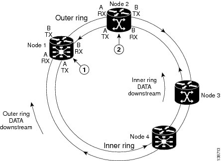
Intelligent Protection Switching (IPS) provides IP self-healing and restoration, and performance monitoring after a link or node failure. There are two SRP IPS modes:

  • Automatic SRP IPS mode takes effect when the SRP ring detects an event, a fiber cut, or a node failure, and remains in effect until the trigger condition is cleared. Once the trigger is cleared, the SRP IPS mode remains in effect until the wait-to-restore (WTR) value expires.

  • User-configured SRP IPS mode takes effect as soon as you enter the command and remains in effect until it is removed by a user command or overridden by an SRP IPS command with higher priority. You can use the no srp ips request forced-switch global configuration command or the srp remove manual-switch EXEC command to negate a user-configured command.

A a user-configured, forced-switch adds a high-priority protection switch wrap on each end of a specified span by entering the user-configured srp ips request forced-switch command. For example, you can enter an srp ips request forced-switch command to force data traffic to one side of the ring before a DPT PLIM is removed from a router slot, or in response to an event.

This table describes the IPS requests in the order of priority, from higher to lower.

Table 1. Explanation of SRP IPS User Requests

SRP IPS Request

Description

Forced-switch

Adds a high-priority protection switch wrap on each end of a specified span by entering the user-configured srp ips request forced-switch command.

Manual-switch

Adds a low-priority protection switch wrap on each end of a specified span by entering the user-configured srp request manual-switch command.


Note

Before removing the DPT PLIM, you can use the srp ips request forced-switch command on both sides of the interface that is to be removed.


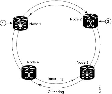
If an automatic or user-configured protection switch is requested for a given span, the node that receives the protection request issues a protection request to the node on the other end of the span using both the short path over the failed span, because the failure may be unidirectional, and the long path around the ring.

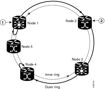
As the protection requests travel around the ring, the protection hierarchy is applied. For example, if a high-priority Signal Fail (SF) request enters the ring, it overrides a preexisting lower-priority request. If an event or a user-configured command enters a low-priority request, it is not allowed if a high-priority request is present on the ring.


Note

An exception is that multiple signal-fail and forced-switch requests can coexist on the SRP ring and will bisect the ring if they occur on separate fiber links.


All protection switches are performed bidirectionally and enter wraps at both ends of a span for transmit and receive directions, even if a failure is only unidirectional.

SUMMARY STEPS

  1. configure
  2. interface srp interface-path-id
  3. srp ips wtr-timer seconds
  4. srp ips timer seconds
  5. srp ips request forced-switch {a | b}
  6. end or commit
  7. srp {request | remove} manual-switch {a | b} interface srp interface-path-id
  8. show srp ips interface srp interface-path-id

DETAILED STEPS

  Command or Action Purpose
Step 1

configure

Example:


RP/0/RP0/CPU0:router# configure

Enters global configuration mode.

Step 2

interface srp interface-path-id

Example:


RP/0/RP0/CPU0:router(config)# interface srp 0/1/0/0

Specifies the SRP interface name in the notation rack/slot/module/port and enters interface configuration mode.

Step 3

srp ips wtr-timer seconds

Example:


RP/0/RP0/CPU0:router(config-if)# srp ips wtr-timer 60

(Optional) Configures the amount of time in seconds that a wrap remains in place after the cause of the wrap is removed.

Step 4

srp ips timer seconds

Example:


RP/0/RP0/CPU0:router(config-if)# srp ips timer 60 a

(Optional) Specifies the frequency of the transmission of IPS requests. The default is 1 second.

Note 
  • We recommend that the IPS timer value be the same for all nodes on a ring. Therefore, if the IPS timer value is changed on one node, you should change it for all nodes on the ring using srp ips timer command.

Step 5

srp ips request forced-switch {a | b}

Example:


RP/0/RP0/CPU0:router(config-if)# srp ips request forced-switch a

(Optional) Adds a high-priority protection switch wrap on each end of a specified span.

Note 
  • Use this command only as necessary, as it disables the node.

Step 6

end or commit

Example:


RP/0/RP0/CPU0:router(config-if)# end

or


RP/0/RP0/CPU0:router(config-if)# commit

Saves configuration changes.

  • When you issue the end command, the system prompts you to commit changes:

    
    Uncommitted changes found, commit them before exiting(yes/no/cancel)?
    [cancel]:
    

    - Entering yes saves configuration changes to the running configuration file, exits the configuration session, and returns the router to EXEC mode.

    - Entering no exits the configuration session and returns the router to EXEC mode without committing the configuration changes.

    - Entering cancel leaves the router in the current configuration session without exiting or committing the configuration changes.

  • Use the commit command to save the configuration changes to the running configuration file and remain within the configuration session.

Step 7

srp {request | remove} manual-switch {a | b} interface srp interface-path-id

Example:


RP/0/RP0/CPU0:router# srp remove manual-switch a interface srp 0/1/0/0

(Optional) Adds or removes a low-priority protection switch wrap on each end of a specified span.

Note 
  • Use this command only as necessary.

Step 8

show srp ips interface srp interface-path-id

Example:


RP/0/RP0/CPU0:router# show srp ips interface srp 0/1/0/0

(Optional) Displays the IPS configuration on the SRP interface.

Configuring Modular Quality of Service CLI (MQC) with SRP

Perform this task to configure quality-of-service (QoS) classifications with SRP using the Modular QoS command-line interface (MQC) feature. This is an optional task.


Note

For more information regarding MQC, refer to Configuring Modular Quality of Service Packet Classification on Cisco IOS XR Software and Cisco IOS XR Modular Quality of Service Command Reference.


SUMMARY STEPS

  1. configure
  2. class-map match-any class-map-name
  3. match mpls experimental topmost exp-value
  4. exit
  5. class-map match-any class-map-name
  6. match precedence precedence-value
  7. exit
  8. policy-map policy-name
  9. class class-name
  10. police cir kbps
  11. set cos cos-value
  12. priority
  13. exit
  14. class class-name
  15. priority
  16. set cos cos-value
  17. exit
  18. exit
  19. interface srp interface-path-id
  20. service-policy output policy-map
  21. end or commit

DETAILED STEPS

  Command or Action Purpose
Step 1

configure

Example:


RP/0/RP0/CPU0:router# configure

Enters global configuration mode.

Step 2

class-map match-any class-map-name

Example:


RP/0/RP0/CPU0:router(config)# class-map match-any voice

Enters class map configuration mode.

  • Creates a class map to be used for matching packets to the class whose name you specify.

  • If you specify match-any , one of the match criteria must be met for traffic entering the traffic class to be classified as part of the traffic class.

Step 3

match mpls experimental topmost exp-value

Example:


RP/0/RP0/CPU0:router(config-cmap)# match mpls experimental topmost 4

Configures a class map so that the three-bit experimental (EXP) field in the topmost Multiprotocol Label Switching (MPLS) labels are examined for EXP field values.

  • The EXP value argument is specified as the exact value from 0 to 7.

Step 4

exit

Example:


RP/0/RP0/CPU0:router(config-cmap)# exit

Exits the current submode.

Step 5

class-map match-any class-map-name

Example:


RP/0/RP0/CPU0:router(config)# class-map match-any ctrl

Enters class map configuration mode.

  • Creates a class map to be used for matching packets to the class whose name you specify.

  • If you specific match-any , one of the match criteria must be met for traffic entering the traffic class to be classified as part of the traffic class.

Step 6

match precedence precedence-value

Example:


RP/0/RP0/CPU0:router(config-cmap)# match precedence internet

(Optional) Identifies IP precedence values as match criteria.

  • The range is from 0 to 63.

  • Reserved keywords can be specified instead of numeric values.

Step 7

exit

Example:


RP/0/RP0/CPU0:router(config-cmap)# exit

Exits the current submode.

Step 8

policy-map policy-name

Example:


RP/0/RP0/CPU0:router(config)# policy-map srp-policy

Enters policy map configuration mode.

  • Creates or modifies a policy map that can be attached to one or more interfaces to specify a service policy.

Step 9

class class-name

Example:


RP/0/RP0/CPU0:router(config-pmap)# class voice

Specifies the name of the class whose policy you want to create or change.

Step 10

police cir kbps

Example:


RP/0/RP0/CPU0:router(config-pmap-c)# police cir 2000000

Configures traffic policing.

Note 
  • 2000000 represents 10 percent of the interface line rate.

Step 11

set cos cos-value

Example:


RP/0/RP0/CPU0:router(config-pmap-c)# set cos 4

Sets the Layer 2 class of service (CoS) value of an outgoing packet.

Step 12

priority

Example:


RP/0/RP0/CPU0:router(config-pmap-c)# priority

Gives priority to a class of traffic belonging to a policy map.

Note 
  • The priority command should only be used if the set cos command is also used and specifies a cos value greater then or equal to 2.

Step 13

exit

Example:


RP/0/RP0/CPU0:router(config-pmap-c)# exit

Exits the current submode.

Step 14

class class-name

Example:


RP/0/RP0/CPU0:router(config-pmap)# class ctrl

Specifies the name of the class whose policy you want to create or change.

Step 15

priority

Example:


RP/0/RP0/CPU0:router(config-pmap-c)# priority

Gives priority to a class of traffic belonging to a policy map.

Note 
  • The priority command should only be used if the set cos command is also used and specifies a cos value greater than or equal to 2.

Step 16

set cos cos-value

Example:


RP/0/RP0/CPU0:router(config-pmap-c)# set cos 6

Sets the Layer 2 CoS value of an outgoing packet.

Step 17

exit

Example:


RP/0/RP0/CPU0:router(config-pmap-c)# exit

Exits the current submode.

Step 18

exit

Example:


RP/0/RP0/CPU0:router(config-pmap)# exit

Exits the current submode.

Step 19

interface srp interface-path-id

Example:


RP/0/RP0/CPU0:router(config)# interface srp 0/1/0/0

Specifies the SRP interface in the notation rack/slot/module/port and enters interface configuration mode.

Step 20

service-policy output policy-map

Example:


RP/0/RP0/CPU0:router(config-if)# service-policy output srp-policy

Attaches a policy map to an input or output interface to be used as the service policy for that interface.

  • The traffic policy evaluates all traffic leaving that interface.

Step 21

end or commit

Example:


RP/0/RP0/CPU0:router(config-if)# end

or


RP/0/RP0/CPU0:router(config-if)# commit

Saves configuration changes.

  • When you issue the end command, the system prompts you to commit changes:

    
    Uncommitted changes found, commit them before exiting(yes/no/cancel)?
    [cancel]:
    

    - Entering yes saves configuration changes to the running configuration file, exits the configuration session, and returns the router to EXEC mode.

    - Entering no exits the configuration session and returns the router to EXEC mode without committing the configuration changes.

    - Entering cancel leaves the router in the current configuration session without exiting or committing the configuration changes.

  • Use the commit command to save the configuration changes to the running configuration file and remain within the configuration session.

Adding a Node to the Ring

This task describes how to add a node to an existing SRP ring, using Cisco IOS XR commands that insert forced-switch wraps away from the area on the fiber where the node is being added, to ensure a minimal loss of data traffic.

For the purpose of this example, a fifth node is added to a four-node ring. Node 5 is added between Node 1 and Node 4. The below figures show the physical configuration using a single DPT PLIM and logical configuration.

SUMMARY STEPS

  1. configure
  2. interface srp interface-path-id
  3. srp ips request forced-switch {a | b}
  4. end or commit
  5. Disconnect the fiber-optic cables connecting Node 1 to Node 4.
  6. Connect the cables to add the new node while observing the receive (RX) and transmit (TX) cabling relationship.
  7. interface srp interface-path-id
  8. no srp ips request forced-switch {a | b}
  9. end or commit
  10. show srp ips
  11. show srp errors

DETAILED STEPS

  Command or Action Purpose
Step 1

configure

Example:


RP/0/RP0/CPU0:router1# configure

Enters global configuration mode.

Step 2

interface srp interface-path-id

Example:


RP/0/RP0/CPU0:router1(config)# interface srp 0/1/0/0

Specifies the SRP interface in the notation rack/slot/module/port for Node 1 and enters interface configuration mode.

Step 3

srp ips request forced-switch {a | b}

Example:


RP/0/RP0/CPU0:router1(config-if)# srp ips request forced-switch a

(Optional) Adds a high-priority protection switch wrap on each end of the specified span. This stops traffic flowing from Node 1 on the fiber that will be disconnected and creates a wrap next to Node 1 on Side A.

Note 
  • If you choose not to use the srp ips request forced-switch command, as soon as you perform Step 5, a signal failure is detected by Node 1 and Node 4, and they automatically insert two signal-fail wraps away from the failure between the nodes. We recommend that you use the srp ips request forced-switch command to minimize data loss.

Step 4

end or commit

Example:


RP/0/RP0/CPU0:router1(config-if)# end

or


RP/0/RP0/CPU0:router1(config-if)# commit

Saves configuration changes.

  • When you issue the end command, the system prompts you to commit changes:

    
    Uncommitted changes found, commit them before exiting(yes/no/cancel)?
    [cancel]:
    

    - Entering yes saves configuration changes to the running configuration file, exits the configuration session, and returns the router to EXEC mode.

    - Entering no exits the configuration session and returns the router to EXEC mode without committing the configuration changes.

    - Entering cancel leaves the router in the current configuration session without exiting or committing the configuration changes.

  • Use the commit command to save the configuration changes to the running configuration file and remain within the configuration session.

Step 5

Disconnect the fiber-optic cables connecting Node 1 to Node 4.

Step 6

Connect the cables to add the new node while observing the receive (RX) and transmit (TX) cabling relationship.

See the below figure.

Step 7

interface srp interface-path-id

Example:


RP/0/RP0/CPU0:router1(config)# interface srp 0/1/0/0

Specifies the SRP interface in the notation rack/slot/module/port for Node 1 and enters interface configuration mode.

Step 8

no srp ips request forced-switch {a | b}

Example:


RP/0/RP0/CPU0:router1(config-if)# no srp ips request forced-switch a

Removes the high-priority protection switch wrap on each end of the specified span. This allows traffic to flow again from Node 1. (See the below figure.)

Note 
  • If you performed Step 3, then you must use the no srp ips request forced-switch command to remove the wraps. If you did not perform Step 3, the wraps are removed automatically when the WTR timer has expired.

Step 9

end or commit

Example:


RP/0/RP0/CPU0:router1(config-if)# end

or


RP/0/RP0/CPU0:router1(config-if)# commit

Saves configuration changes.

  • When you issue the end command, the system prompts you to commit changes:

    
    Uncommitted changes found, commit them before exiting(yes/no/cancel)?
    [cancel]:
    

    - Entering yes saves configuration changes to the running configuration file, exits the configuration session, and returns the router to EXEC mode.

    - Entering no exits the configuration session and returns the router to EXEC mode without committing the configuration changes.

    - Entering cancel leaves the router in the current configuration session without exiting or committing the configuration changes.

  • Use the commit command to save the configuration changes to the running configuration file and remain within the configuration session.

Step 10

show srp ips

Example:


RP/0/RP0/CPU0:router5# show srp ips

Confirms that the wraps have disappeared and the new node is part of the ring. (See the figure below.)

Step 11

show srp errors

Example:


RP/0/RP0/CPU0:router5# show srp errors

Confirms that there are no problems with the new ring configuration. If there are failures, note the status on the LEDs to determine what the problem might be.

Figure 2. Four Routers on the SRP Ring (Each Router Using Two Physical Ports)

1

Cisco CRS-1 Router

2

Cisco 12000 Series Router

Figure 3. SRP Ring Topology with a Fifth Node Added to a Wrapped Ring

1

Cisco CRS-1 Router

2

Cisco 12000 Series Router

Configuring Single Ring Recovery on SRP Interfaces

Perform this task to configure the Single Ring Recover (SRR) protocol. SRR allows SRP rings to operate over a single fiber in the event of multiple failures on one of the two counter-rotating SRP rings, thereby allowing the system to operate with full connectivity.

The following configuration is optional. SRR is enabled by default.


Note

Cisco Systems recommends the use of the default bandwidth and timer values for optimal running of the SRR protocol.


Before you begin

SRR requires a fully SRR compatible ring to operate. In order for SRR to converge:

  • all nodes on the SRP ring must support SRR

  • all nodes must support the same SRR version

    If one or more of the nodes does not support SRR or has a different SRR version, SRR will have no effect and the ring will operate like a standard SRP ring without SRR.

SUMMARY STEPS

  1. configure
  2. interface srp instance
  3. srp srr bandwidth value
  4. srp srr timer seconds
  5. srp srr wtr-timer seconds
  6. end or commit
  7. show srp srr interface srp instance

DETAILED STEPS

  Command or Action Purpose
Step 1

configure

Example:


RP/0/RP0/CPU0:router# configure

Enters global configuration mode.

Step 2

interface srp instance

Example:


RP/0/RP0/CPU0:router(config)# interface srp 0/4/0/1

Enters the SRP interface configuration mode.

Step 3

srp srr bandwidth value

Example:


RP/0/RP0/CPU0:router(config-if)# srp srr bandwidth 400

Specifies the bandwidth for the interface in megabits per second (Mbps) when the interface operates on a single ring. The value is between 1 to the maximum possible bandwidth of the node.

Step 4

srp srr timer seconds

Example:


RP/0/RP0/CPU0:router(config-if)# srp srr timer 10

Specifies the periodic timer, in seconds, for SRR messages in the Idle state. The default is 10 seconds.

Step 5

srp srr wtr-timer seconds

Example:


RP/0/RP0/CPU0:router(config-if)# srp srr wtr-timer 10

Specifies the amount of time in seconds that the ring operates on one ringe after the cause of the failure is removed. The default is 60 seconds.

Step 6

end or commit

Example:


RP/0/0/CPU0:router(config-if)# end

or


RP/0/0/CPU0:router(config-if)# commit

Saves configuration changes.

  • When you issue the end command, the system prompts you to commit changes:

    
    Uncommitted changes found, commit them before exiting(yes/no/cancel)?
    [cancel]:
    

    - Entering yes saves configuration changes to the running configuration file, exits the configuration session, and returns the router to EXEC mode.

    - Entering no exits the configuration session and returns the router to EXEC mode without committing the configuration changes.

    - Entering cancel leaves the router in the current configuration session without exiting or committing the configuration changes.

  • Use the commit command to save the configuration changes to the running configuration file and remain within the configuration session.

Step 7

show srp srr interface srp instance

Example:


RP/0/RP0/CPU0:router# show srp srr interface srp 0/1/0/0

(Optional) Displays the SRR configuration on the SRP interface.

Configuration Examples for SRP Interfaces

This section provides the following configuration examples:

Enabling SRP: Examples

This example shows how to enable SRP on a PLIM port.


RP/0/RP0/CPU0:router# configure
RP/0/RP0/CPU0:router(config)# hw-module port 0 srp location 0/3/CPU0
RP/0/RP0/CPU0:router(config)# hw-module port 1 srp location 0/3/CPU0
RP/0/RP0/CPU0:router(config)# commit
RP/0/RP0/CPU0:router(config)# end
RP/0/RP0/CPU0:router# hw-module node 0/3/CPU0 reload

<Wait for LC to be reloaded, and interface created.  Or can use 'preconfigure'...>

This example shows how to enable SRP on four OC-48/STM-16 SPA ports.


RP/0/RP0/CPU0:router# configure
RP/0/RP0/CPU0:router(config)# hw-module port 0 srp location 0/3/CPU0 spa-bay 2
RP/0/RP0/CPU0:router(config)# hw-module port 1 srp location 0/3/CPU0 spa-bay 2
RP/0/RP0/CPU0:router(config)# hw-module port 2 srp location 0/3/CPU0 spa-bay 2
RP/0/RP0/CPU0:router(config)# hw-module port 3 srp location 0/3/CPU0 spa-bay 2
RP/0/RP0/CPU0:router(config)# commit
RP/0/RP0/CPU0:router(config)# end
RP/0/RP0/CPU0:router# hw-module subslot 0/3/CPU0 reload

<Wait for LC to be reloaded, and interface created.  Or can use 'preconfigure'...>

This example shows how to enable SRP on two OC-192/STM-64 SPA ports, which comprise an SRP interface.


RP/0/RP0/CPU0:router# configure
RP/0/RP0/CPU0:router(config)# hw-module port 0 srp location 0/3/CPU0 spa-bay 0
RP/0/RP0/CPU0:router(config)# hw-module port 0 srp location 0/3/CPU0 spa-bay 1
RP/0/RP0/CPU0:router(config)# commit
RP/0/RP0/CPU0:router(config)# hw-module subslot 0/3/0 shutdown
RP/0/RP0/CPU0:router(config)# hw-module subslot 0/3/1 shutdown
RP/0/RP0/CPU0:router(config)# commit
RP/0/RP0/CPU0:router(config)# no hw-module subslot 0/3/0 shutdown
RP/0/RP0/CPU0:router(config)# no hw-module subslot 0/3/1 shutdown
RP/0/RP0/CPU0:router(config)# commit

Configuring Basic SRP: Example

This example shows how to configure the basic interface configuration for SRP.


RP/0/RP0/CPU0:router# configure
RP/0/RP0/CPU0:router(config)# controller SONET 0/3/0/0 clock source internal
RP/0/RP0/CPU0:router(config)# controller SONET 0/3/0/1 clock source internal
RP/0/RP0/CPU0:router(config)# interface SRP 0/3/0/0
RP/0/RP0/CPU0:router(config-if)# ipv4 address 172.18.189.38 255.255.255.224
RP/0/RP0/CPU0:router(config-if)# no shutdown
RP/0/RP0/CPU0:router(config-if)# commit
RP/0/RP0/CPU0:router(config)# end

Configuring Modular QoS with SRP: Example

This example shows how to configure two quality-of-service (QoS) classes. One is for voice traffic and is identified by an MPLS experimental bit value of 4; the second is control traffic that is identified by an IP precedence value of 6. Both classes of traffic are sent to the SRP high priority queue and are marked with high SRP priority (4 and 6).


Last configuration change at 04:56:06 UTC Tue Sep 06 2005 by lab
!
hostname router
class-map match-any ctrl
 match precedence internet
!
class-map match-any voice
 match mpls experimental topmost 4
!
policy-map srp-policy
 class voice
  police cir 2000000
  set cos 4
  priority
 !
 class ctrl
  priority
  set cos 6
 !
!
interface SRP0/7/0/0
 description "Connected to 3-nodes ring"
 service-policy output srp-policy
 ipv4 address 30.30.30.2 255.255.255.0

Creating a Metropolitan-Area Network with SRP Rings

In this example, an OC-48c/STM-16c SRP ring is used to interconnect two OC-12c/STM-4c access rings to form a larger hierarchical SRP ring topology by directly connecting two Cisco 12000 Series Internet Routers together using direct fiber connections without the use of SONET Add/Drop Multiplexers (ADMs).


Note

Each SRP ring must be on a different subnet.

Figure 4. Two OC12 SRP Rings Connected to an OC48 SRP Ring

This configuration example shows the Cisco IOS commands used to configure SRP rings on the GSR+ A and GSR+ B routers in the above figure.

GSR+ A Configuration


GSR+A:
Building configuration...
Current configuration:
!
version 12.0
no service pad
service timestamps debug uptime
service timestamps log uptime
service password-encryption
!
hostname GSR+A
!
!
hw-module slot 4 srp
!
ip subnet-zero
no ip domain-lookup
ip multicast-routing distributed
 ip pim rp-address 10.8.1.20 1
!
interface Loopback0
ip address 10.0.0.1 255.255.255.252
no ip directed-broadcast
!
interface SRP1/0
ip address 10.10.10.1 255.255.255.192
no ip redirects
no ip directed-broadcast
ip pim sparse-mode
ip mroute-cache distributed
load-interval 30
!
interface Ethernet0
ip address 10.100.1.2 255.255.255.0
no ip directed-broadcast
no ip route-cache cef
!
interface SRP4/0
ip address 10.10.20.1 255.255.255.192
no ip redirects
no ip directed-broadcast
ip pim sparse-mode
ip mroute-cache distributed
load-interval 30
 srp topology-timer 1
 srp ips wtr-timer 10
!

router ospf 100
network 10.10.10.0 0.0.0.255 area 1
network 10.10.20.0 0.0.0.255 area 0
network 10.0.0.1 0.0.0.0 area 0

auto-cost reference-bandwidth 2488
!
ip classless
!

GSR B Configuration


GSR+B:
Building configuration...
Current configuration:
!
version 12.0
no service pad
service timestamps debug uptime
service timestamps log uptime
service password-encryption
!
hostname GSR+B
!
!
hw-module slot 4 srp
!
ip subnet-zero
no ip domain-lookup
ip multicast-routing distributed
 ip pim rp-address 10.8.1.20 1
!
interface Loopback0
ip address 10.0.0.2 255.255.255.252
no ip directed-broadcast
!
interface SRP1/0
ip address 10.10.30.1 255.255.255.192
no ip redirects
no ip directed-broadcast
ip pim sparse-mode
ip mroute-cache distributed
load-interval 30
!
interface Ethernet0
ip address 10.100.1.5 255.255.255.0
no ip directed-broadcast
no ip route-cache cef
!
interface SRP4/0
ip address 10.10.20.2 255.255.255.192
no ip redirects
no ip directed-broadcast
ip pim sparse-mode
ip mroute-cache distributed
load-interval 30
 srp topology-timer 1
 srp ips wtr-timer 10
!
router ospf 100

network 10.10.30.0 0.0.0.255 area 2
 network 10.10.20.0 0.0.0.255 area 0
 network 10.0.0.2 0.0.0.0 area 0
auto-cost reference-bandwidth 2488
!
ip classless