- Preface
- Overview
- Installing and Removing Power Components
- Installing and Removing Air Circulation Components
- Installing and Removing Fabric Cards and Card Components
- Installing and Removing Exterior Cosmetic Components
- Upgrading Chassis Components
- Cisco CRS-1 Carrier Routing System Fabric Card Chassis Specifications
- Product IDs
Cisco CRS Carrier Routing System Fabric Card Chassis Installation Guide
Bias-Free Language
The documentation set for this product strives to use bias-free language. For the purposes of this documentation set, bias-free is defined as language that does not imply discrimination based on age, disability, gender, racial identity, ethnic identity, sexual orientation, socioeconomic status, and intersectionality. Exceptions may be present in the documentation due to language that is hardcoded in the user interfaces of the product software, language used based on RFP documentation, or language that is used by a referenced third-party product. Learn more about how Cisco is using Inclusive Language.
- Updated:
- February 15, 2017
Chapter: Installing and Removing Power Components
- Power Systems Overview
- Power Component Information Common to the Two Types of Power Systems
- DC Power Systems
- AC Power Systems
- Installing a Modular Configuration Power Shelf
- Removing a Modular Configuration Power Shelf
- Installing Power Shelf Grounding Brackets
- Removing Power Shelf Grounding Brackets
- Installing AC or DC Power Self Wiring
- Removing AC or DC Power Shelf Wiring
- Installing a Modular Configuration Alarm Module
- Removing a Modular Configuration Alarm Module
- Installing a Modular Configuration Power Module
- Removing a Modular Configuration Power Module
- Installing a Modular Configuration Power Module Slot Cover
- Removing a Modular Configuration Power Module Slot Cover
- Power Up and Power Down a Chassis with Modular Configuration Power
- Converting from One Modular Configuration Power System to Another
Installing and Removing Power Components
This chapter provides instructions on how to install and remove the Cisco CRS Carrier Routing System Fabric Card Chassis (FCC) power components.
- Power Systems Overview
- Power Component Information Common to the Two Types of Power Systems
- How to Install and Remove Fixed Configuration Power Shelf Components
- How to Install and Remove Modular Configuration Power Components
- How to Convert a Chassis from Fixed Configuration Power to Modular Configuration Power
Power Systems Overview
There are two options for power systems: the fixed configuration power system and the modular configuration power system. Power components are not interchangeable between the fixed and modular configuration power system.
Fixed configuration power system consists of two power shelves, DC power entry modules (PEMs) or AC rectifiers, and alarm modules. It is available in versions for DC and AC power supplies. The AC version requires either 3-phase AC-Delta or 3-phase AC-Wye input power to the power shelves. In redundant configuration, the fixed configuration power system provides power sharing per load zone. The fixed configuration power system includes SNMP MIBS and XML support.
Modular configuration power system consists of two power shelves, AC or DC power modules (PMs), and alarm modules. It is available in versions for DC and AC power supplies. However, unlike the fixed configuration power system, the AC version of the modular configuration power system requires single-phase AC input power to the power shelves; there is no 3-phase AC-Wye or AC-Delta. If you have 3-phase AC Delta or AC Wye at your equipment, a Cisco CRS Power Distribution Unit (PDU) will be required to convert 3-phase AC input power to single-phase AC input power for the power shelf. At the shelf level, the power system provides 2N redundancy; the PMs themselves provide load-share redundancy. The modular configuration power system also includes SNMP MIBS and XML support.
 Note | In a modular configuration AC power system, PDU refers to the Cisco CRS PDU which is required to convert 3-phase AC-Wye or AC-Delta input power to single-phase AC input power for the modular configuration AC power shelf. For further information, refer to Cisco CRS 3-Phase AC Power Distribution Unit Installation Guide . |
This chapter contains the following topics:
Power Component Information Common to the Two Types of Power Systems
This section introduces general information shared by the fixed configuration power components and the modular configuration power components in the following topics:
Basic Chassis Power Details
The FCC can be configured with either an AC-input power subsystem or a DC-input power subsystem. Site power requirements differ, depending on the source voltage used. Follow these precautions and recommendations when planning power connections to the router:
- Check the power at your site before installation and periodically after installation to ensure that you are receiving clean power. Install a power conditioner, if necessary.
- Install proper grounding to avoid damage from lightning and power surges.
The FCC requires that at least one power shelf and its components be installed to operate properly; however, if you install only one power shelf and its components, your system will not be 2N redundant.
Two types of power shelves exist: an AC power shelf and a DC power shelf. A fixed configuration AC power shelf houses the AC rectifiers, while a fixed configuration DC power shelf houses the DC PEMs. A modular configuration AC power shelf houses the AC PMs, while a modular configuration DC power shelf houses the DC PMs. It is required that you use only one type of power shelf in a chassis at a time.
Note | In a modular configuration power system, both AC and DC power supplies are referred to as power modules (PMs) |
 Warning | This unit might have more than one power supply connection. All connections must be removed to de-energize the unit. Statement 1028 |
Bonding and Grounding Guidelines
The router chassis has a safety earth ground connection in conjunction with power cabling to the fixed configuration power shelves. The chassis allows you to connect the central office ground system or interior equipment grounding system to the bonding and grounding receptacles on the router chassis, when either a fixed or modular configuration power system is installed. Two sets of two threaded ground inserts are located on top of the chassis rear (OIM) side panel on the back of the chassis to the left of the lower power shelf, and two sets of threaded ground inserts are located at the bottom rear of the chassis (see the figure titled NEBS Bonding and Grounding Points). These grounding points are also referred to as the network equipment building system (NEBS) bonding and grounding points. The location of the grounding points on the FCC is the same for both fixed and modular configuration power systems.
Note | These bonding and grounding receptacles satisfy the Telcordia NEBS requirements for supplemental bonding and grounding connections. |
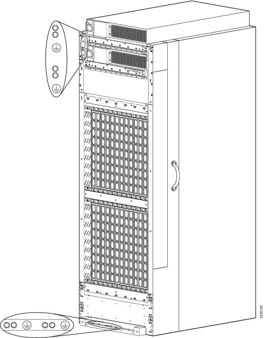
The top grounding points are obscured by a cover plate. When the cover plate is removed, you can easily see the labels indicating the location of the grounding points. Two grounding points are provided at the top of the chassis; although you may use both if you wish, only one is needed for NEBS grounding purposes. This figure shows the NEBS bonding and grounding points on the rear of the chassis, located next to the modular configuration DC power shelves.
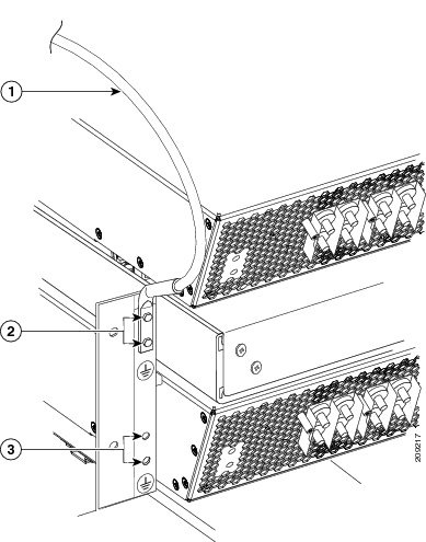
|
1 |
Chassis ground cable |
|
2 |
Top NEBS bonding and grounding points |
|
3 |
Bottom NEBS bonding and grounding points (fixed configuration power only) |
Note | A 45-degree grounding lug is shown in the figure titled NEBS Bonding and Grounding Points at Top of Chassis— With Modular Configuration DC Power Shelves Installed. A 180-degree (straight) grounding lug can also be used. |
Note | Two NEBS bonding and grounding points are provided. Only the top grounding point can be used if modular configuration power shelves are installed. |
Modular configuration power shelf grounding is accomplished by installing an external ground bracket between the power shelves and attached to the chassis. The bolts that connect the external grounding brackets to the chassis and the power shelf have a torque value of 30 in-lb (3.39 N-m). See the Installing Power Shelf Grounding Brackets for more information.
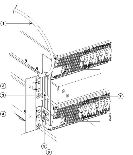
|
1 |
Chassis ground cable |
5 |
Two M6 hex nuts attaching grounding L-bracket to shelf grounding bracket |
|
2 |
Two M6 hex bolts attaching ground lug to chassis |
6 |
Grounding L-bracket |
|
3 |
Shelf grounding bracket |
7 |
Four M6 hex bolts attaching shelf grounding bracket to power shelves |
|
4 |
Two M6 hex bolts attaching grounding L-bracket to chassis |
|
|
Installing the Chassis Ground cable
This section describes how to install the ground cable on the FCC.
Prerequisites
To ensure a satisfactory ground connection, you need the following parts:
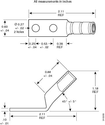
- One grounding lug that has two M6 bolt holes with 0.63 inches (5/8 inch) (1.60 cm) of spacing center to center between them and a 6-AWG or larger multistrand copper cable.
- The grounding lug used can be either a 180-degree (straight) lug, or a 45-degree angle lug, as shown in the figures below. We recommend that you use a 45-degree angle ground lug for the upper grounding point.
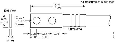
- Two M6 hex head bolts and integrated locking washers are pre-installed on the chassis.
- Although we recommend at least 6-AWG multistrand copper ground cable, the actual ground cable diameter and length depends on your router location and site environment. This cable is not available from Cisco Systems; it is available from any commercial cable vendor. The ground cable should be sized according to local and national installation requirements.
Note | The DC return of this system should remain isolated from the system frame and chassis (DC-I: Isolated DC Return). |
Required Tools and Equipment
You need the following tools and equipment to perform this task:
- Ground lug
- Ground cable
- Crimping tool and lug specific die
- 10-mm 6 pt. combination wrench
- Torque wrench with 10-mm 6 pt. socket and rated accuracy at 30 in.-lb (3.39 N-m)
Steps
To attach the ground cable to the chassis, perform the following steps:
1. Use the crimping tool mandated by the lug manufacturer to crimp the lug to the ground cable.
2. Using the 10-mm wrench, attach the ground cable to the grounding point on top of the chassis rear (OIM) side panel, as shown in Figure 2 and Figure 3. Use the torque wrench to tighten to a torque of 30 in.-lb (3.39 N-m).
DETAILED STEPS
| Step 1 | Use the crimping tool mandated by the lug manufacturer to crimp the lug to the ground cable. |
| Step 2 | Using the 10-mm wrench, attach the ground cable to the grounding point on top of the chassis rear (OIM) side panel, as shown in Figure 2 and Figure 3. Use the torque wrench to tighten to a torque of 30 in.-lb (3.39 N-m). |
DC Power Systems
Each DC-powered chassis contains two DC power shelves for 2N redundancy. The shelves contain the input power connectors.
- In the fixed configuration power system, each power shelf contains two DC PEMs. The PEMs are field replaceable. Each DC PEM has its own circuit breaker.
- In the modular configuration power system, each power shelf can accept up to six DC PMs. The power shelves and DC PMs are field replaceable.
Note | Depending on the hardware deployed at your site, your system may not consume the maximum power supplied by the power system. |
- Fixed Configuration DC Power
- Modular Configuration DC Power
- Input-Power-Present-LEDs
- DC Power Cable Characteristics
Fixed Configuration DC Power
The FCC fixed configuration DC power system provides 8,800 watts to power the chassis.
Due to its power load zones, the FCC using fixed configuration power requires a total of eight dedicated 60 A DC input power connections, two for each DC PEM, to provide DC power to all six power zones. We recommend that you have two separate, redundant –48 VDC power battery sources to provide power to the FCC. Connect the four “A” 60 Amp DC inputs to the upper power shelf to one battery, and the four “B” 60 Amp inputs to the lower power shelf to the other battery.
At sites where the FCC is equipped with a DC-input power shelf and DC PEMs, observe the following guidelines:
- All power connection wiring should follow the rules and regulations in the National Electrical Code (NEC) and any local codes.
- Each DC-input PEM connection is rated at 60 A maximum. A dedicated, commensurately rated DC power source is required for each PEM connection.
- For DC power cables, we recommend that you use commensurately rated, high-strand-count copper cable. Each DC PEM requires two DC inputs of nominal –48/–60 VDC, 60 A service. Each DC input consists of one pair of cable leads, source DC (–) and source DC return (+). Each power shelf requires one grounding cable. The length of the cables depends on your router location. These cables are not available from Cisco Systems; they are available from any commercial vendor.
- DC power cables must be terminated by cable lugs at the power shelf end. The lugs should be dual-hole and able to fit over M6 terminal studs at 0.63 in (5/8 inch) (1.60 cm) centers. For example, Panduit part number LCD2-14A-Q; see this figure.
- Maximum wire size at the DC input terminal block is 2 AWG.
The following figure shows a typical DC power distribution scheme. The ground cable is to the far left on the shelf. The DC terminal block power connector studs have a 20 in.-lb (2.26 N-m) torque value; the power shelf ground cable connector studs have a 30 in.-lb (3.39 N-m) torque value.
The color coding of the source DC power cable leads depends on the color coding of the site DC power source. Typically, green or green and yellow indicates that the cable is a ground cable. Follow your local practices for cable color code and markings. You must ensure that the power cables are connected to the DC-input power shelf terminal studs in the proper positive (+) and negative (–) polarity.
Sometimes, the source DC cable leads might have a positive (+) or a negative (–) label, but you must verify the polarity by measuring the voltage between the DC cable leads. When making the measurement, the positive (+) lead and the negative (–) lead must always match the (+) and (–) labels on the power shelf.
 Caution | The DC-input PEM contains circuitry to trip the breaker on the PEM if it detects a reverse-polarity condition. When installing DC power cables, make sure that the polarity of the DC input wiring is correct. |
This figure shows the cable wiring on the rear of the fixed configuration DC power shelf.
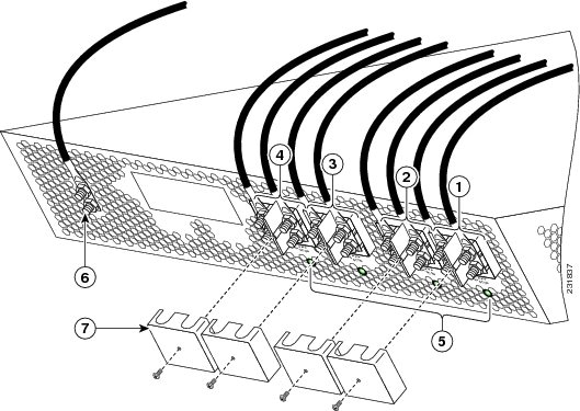
|
1 |
PEM O, input 1 |
5 |
Input-power-present LEDs |
|
2 |
PEM 0, input 2 |
6 |
Ground lugs and nuts |
|
3 |
PEM 1, input 3 |
7 |
Terminal block cover |
|
4 |
PEM 1, input 4 |
|
|
This table lists the DC input current and voltage specifications.
|
Nominal input voltage |
–48 VDC North America–60 VDC European Community(range: –42 VDC to –75 VDC) |
|
Input line current |
50 A maximum at –48 VDC40 A maximum at –60 VDC |
|
Inrush current |
168 A peak at –75 VDC(maximum for 1 ms) |
Each wiring block on the power shelf contains two sets of terminals, one positive and one negative, and is covered by a plastic terminal block cover that snaps onto the power shelf and is secured by a screw to a torque value of 4 to 5 in.-lb (.46 to .58 N-m). You must remove the terminal block cover or rotate it out of the way before you work with the cables.
For additional power details, see Appendix 1, “Cisco CRS-1 Carrier Routing System Fabric Card Chassis Specifications” or Cisco CRS Carrier Routing System Multishelf System Description .
Modular Configuration DC Power
The FCC modular configuration DC power system can provide up to 12,600 watts to power the chassis. However, by default, the power capability of a system when shipped, with four DC PMs per shelf, is 8,400 watts.
Note | Depending on the hardware deployed at your site, your system may not consume the maximum power supplied by the power system. |
Each modular configuration DC power shelf supports up to six DC PMs. The power shelves and DC PMs are field replaceable.
This figure shows the cables and terminal block covers for the modular configuration power shelf.
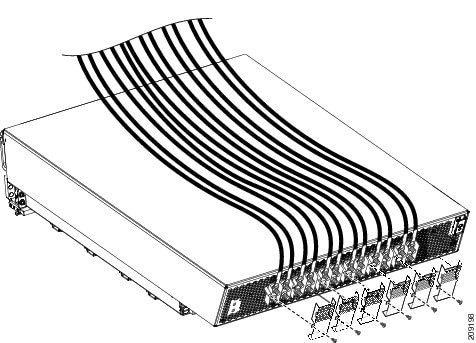
Each power shelf operates with up to six DC inputs of –48/–60 VDC (nominal), 60 A. The power shelf accepts input DC power in the range –40 to –72 VDC.
This table lists the modular configuration DC input current and voltage specifications.
|
Nominal input voltage |
–48 VDC North America–60 VDC European Community(range: –40 VDC to –72 VDC) |
|
Input line current |
50 A maximum at –48 VDC40 A maximum at –60 VDC60 A maximum at –40 VDC |
Each wiring block on the modular configuration DC power shelf contains two sets of terminals, one positive and one negative, and is covered by a plastic terminal block cover that is secured by a screw to a torque value of 5 to 7 in-lb (0.56 to 0.79 N-m). Each DC power cable is connected to the power shelf with a torque value of 20 in-lb (2.26 N-m). Maximum wire size at the DC input terminal block is 2 AWG.
The power supply terminal posts are centered 0.63 inches (5/8 inch) (1.60 cm) apart and are M6-threaded. We recommend that you use an appropriately sized 180-degree angle (straight) industry standard 2-hole, standard barrel compression lug, as shown in this figure.
The power shelf grounding is accomplished by installing an external ground bracket between the power shelves and attached to the chassis. The bolts that connect the external grounding brackets to the chassis and the power shelf have a torque value of 30 in-lb (3.39 N-m).
For additional power details, see Appendix 1, “Cisco CRS-1 Carrier Routing System Fabric Card Chassis Specifications” or Cisco CRS Carrier Routing System Multishelf System Description .
Input-Power-Present-LEDs
In both power configurations, the DC input-power-present LEDs provide a visual indication to service personnel that the is voltage present across the input terminal connection. The figure titled Input-Power-Present LEDs-Fixed Configuration DC Power Shown shows the DC input-power-present LEDs on the rear of the fixed configuration DC power shelf. The modular configuration DC power shelf has similar visual indicators. The LED provides a warning to service personnel that there is power present.
Note | Power should be disconnected before servicing the input power connections. |
This figure shows the input-power-present LEDs on the rear of the fixed configuration DC power shelf.
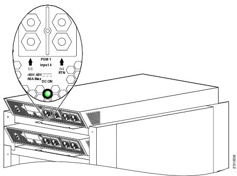
This figure shows the input-power -present LEDs on the rear of the fixed configuration DC power shelf.
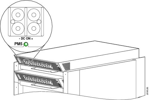
The input-power-present LED starts to light up when the voltage reaches –20 VDC and the LED gets brighter as voltage increases; the input-power-present LED is fully lit when input voltage reaches –38 VDC.
Caution | If the input voltage polarity is reversed, or if the LED circuit fails, the LED will not light. When this is the case, service personnel should check for hazardous voltages before working on the unit. |
DC Power Cable Characteristics
In both configurations, a conductor must be large enough to meet the voltage loss requirement of your facility. Also, the protective earth conductor must be large enough to carry all the current if the –48 VDC return fails. This latter requirement is for safety.
For site preparation, proper cable size and insulation shall be selected. For a planned power distribution, calculation shall be done prior to meet the proper voltage drop and temperature rise.
AC Power Systems
Each AC powered chassis contains two AC power shelves for 2N redundancy. The shelves contain the input power connectors.
- In the fixed configuration power system, each power shelf contains three AC power rectifiers. The power shelves and AC power rectifiers are field replaceable. Each shelf and AC power rectifier has its own circuit breaker.
- In the modular configuration power system, each shelf can contain up to six AC PMs. The power shelves and the AC PMs are field replaceable.
Note | Depending on the hardware deployed at your site, your system may not consume the maximum power supplied by the power system. |
Fixed Configuration AC Power
The FCC fixed configuration AC power system provides 13,200 watts to power the chassis.Two versions of the 3-phase AC power shelf are available to provide either an AC Delta or an AC Wye input configuration. Each of the AC power shelf versions has a different Cisco part number to distinguish the Wye from the Delta configuration. The AC connections to the FCC are made to terminal blocks on the AC power shelves that have been hard wired for Wye or Delta configuration. All chassis should have two power shelves of the same type, that is, two Delta or two Wye AC power shelves.
In the fixed configuration power system, each power shelf supports three AC-to-DC rectifiers that are field replaceable. The AC-to-DC rectifiers convert 200-to-240 VAC power to –54 VDC used by the FCC chassis.
The AC Wye power shelf has a Wye 3-phase, 5-wire connection: 200 to 240 (L-N)/346 to 415 (L-L) VAC, 3W+N+PE, 50 to 60 Hz, 25 A. For redundant operation, two 3-phase Wye branch circuits are required: 32 A (International), with one power connection to each power shelf.
The AC Delta power shelf has a Delta 3-phase, 4-wire connection: 200 to 240 VAC, 3-phase, 3W+PE, 50 to 60 Hz, 42 A. For redundant operation, two 3-phase Delta 60-A branch circuits are required, with one power connection to each power shelf.
Note | The power cables for the fixed configuration AC power shelves do not arrive preattached and need to be installed. |
For additional power details, see Appendix 1, “Cisco CRS-1 Carrier Routing System Fabric Card Chassis Specifications” or Cisco CRS Carrier Routing System Multishelf System Description .
Modular Configuration AC Power Systems
The FCC modular configuration AC power system can provide up to 18,000 watts to power the chassis. However, by default, the maximum power capability of a system when shipped with three AC PMs is 9,000 watts.
Each modular configuration power shelf supports up to six PMs. The power shelves and PMs are field replaceable.
Note | Depending on the hardware deployed at your site, your system may not consume the maximum power supplied by the power system. |
Unlike the fixed configuration AC power system, which requires 3-phase AC Delta and AC Wye input power, the modular configuration AC power system requires single-phase AC input power. If you have 3-phase AC Delta or AC Wye at your site, a Cisco CRS Power Distribution Unit will be required to convert 3-phase input power to single phase input power for the power shelf. For further information, refer to Cisco CRS Power Distribution Unit Quick Start Guide.
The modular configuration AC power shelf has the following input VAC power requirements:
- Single-phase, 200 to 240 VAC nominal, 50 to 60 Hz, 16 A.Each power shelf contains six IEC-320-C22 receptacles which can accept up to six IEC-320-C21 connector female cords.
Note | If you have a Cisco CRS 3-Phase AC PDU installed, either three or six AC PMs are required to be installed in each modular configuration AC power shelf to maintain a balanced 3-phase power load. If only three AC PMs are required in each power shelf, they must be installed in either slots 0, 1, 2 or slots 3,4,5. |
Note | We recommend that you use appropriate short-circuit protection in compliance with national and local electrical codes. |
For additional power details, see Appendix 1, “Cisco CRS-1 Carrier Routing System Fabric Card Chassis Specifications” or Cisco CRS Carrier Routing System 16-Slot Line Card Chassis System Description .
How to Install and Remove Fixed Configuration Power Shelf Components
This section contains the following procedures:
- Installing a Fixed Configuration Power Shelf
- Removing a Fixed Configuration Power Shelf
- Installing Fixed Configuration AC Power Shelf Cord
- Removing Fixed Configuration AC Power Shelf Wiring
- Installing Fixed Configuration DC Power Shelf Wiring
- Removing Fixed Configuration DC Power Shelf Wiring
- Installing an AC Rectifier or DC PEM
- Removing an AC Rectifier or DC PEM
- Installing a Fixed Configuration Alarm Module
- Removing a Fixed Configuration Alarm Module
- Powering Up and Down a Chassis with Fixed Configuration AC Power
- Powering Up and Down a Chassis with Fixed Configuration DC Power
- Converting from One Fixed Configuration Power System to Another
Installing a Fixed Configuration Power Shelf
This section describes how to install a fixed configuration AC or DC power shelf in the FCC. For information on the difference between the power types, see the DC Power Systems and the AC Power Systems. For complete information on regulatory compliance and safety, see Cisco CRS Carrier Routing System Regulatory Compliance and Safety Information.
The power shelf encloses:
- The power modules: three AC rectifiers for an AC power shelf or two DC PEMs for a DC power shelf
- An alarm module
- Power distribution connections and wiring
The power shelf is installed in the FCC from the front (SFC) side of the chassis. Although differences exist among the different power shelf types (AC Wye, AC Delta, and DC), they are installed in the same manner.
This figure shows a fixed configuration AC power shelf. The fixed configuration DC power shelf is similar.
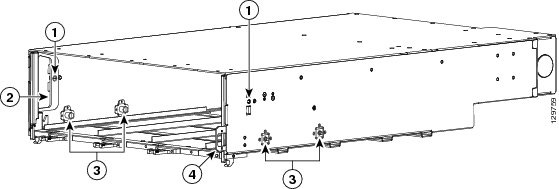
|
1 |
Lever handle captive screws |
3 |
Power shelf captive screws |
|
2 |
Lever handle (left lever handle shown) |
4 |
Power shelf I/O switch |
Prerequisites
Before performing this task, you must first remove the upper grille on the front (SFC) side of the chassis, if installed.
Note | Do not install the power shelf in the chassis with AC rectifiers, DC PEMs, or alarm module installed in the power shelf. |
Required Tools and Equipment
You need the following tools and parts to perform this task:
- ESD-preventive wrist strap
- 1/4-in. x 6-in. long slotted screwdriver
-
Fixed configuration AC or DC Power shelf
- AC Wye power shelf Cisco product number: CRS-FCC-PS-ACW=
- AC Delta power shelf Cisco product number: CRS-FCC-PS-ACD=
- DC power shelf Cisco product number: CRS-FCC-PS-DC=
Steps
To install a fixed configuration AC or DC power shelf, use Figure 1 as a reference and perform the following steps:
1. Attach the ESD-preventive wrist strap to your wrist and connect its leash to one of the ESD connection sockets on the front (SFC) side of the chassis or a bare metal surface on the chassis.
2. Make sure that the power I/0 switch on the shelf, located on the front [SFC] side of the chassis, is in the OFF position.
3. The lever handles are fastened down for shipment. Use the screwdriver to turn the two captive screws, one on each lever handle, to unfasten them.
4. Holding the power shelf underneath with one hand and steadying it with the other, lift the shelf up and slide it partway into one of the power shelf slots on the front (SFC) side of the chassis.
5. Slide the power shelf fully into the chassis and lift the lever handles up to lock the tray into position. Be sure to align the guide pins on the chassis with the holes on the power shelf.
6. Use the screwdriver to turn the two captive screws on the lever handles of the power shelf clockwise to attach them to the interior of the shelf.
7. Use the screwdriver to turn the four captive screws on the interior of the power shelf clockwise to firmly anchor the shelf to the sides of the chassis.
DETAILED STEPS
What to Do Next
After performing this task, wire the power shelf (see the Installing Fixed Configuration AC Power Shelf Cord, and the Installing Fixed Configuration DC Power Shelf Wiring), install the power modules (see the Installing an AC Rectifier or DC PEM), and install the alarm modules (see the Installing a Fixed Configuration Alarm Module).
Removing a Fixed Configuration Power Shelf
This section describes how to remove a fixed configuration AC or DC power shelf from the FCC. For information on the difference between the power types, see the DC Power Systems and the AC Power Systems. For complete information on regulatory compliance and safety, see Cisco CRS Carrier Routing System Regulatory Compliance and Safety Information.
The power shelf is installed in the FCC from the front (SFC) side of the chassis. Although differences exist among the different power shelf types (AC Wye, AC Delta, and DC), they are installed and removed in the same manner. Figure 1 shows a fixed configuration AC Wye power shelf for reference.
Prerequisites
Before performing this task, remove the upper grille on the front (SFC) side of the chassis, if installed.
Required Tools and Equipment
You need the following tools to perform this task:
- ESD-preventive wrist strap
- 1/4-in. x 6-in. long slotted screwdriver
Steps
To remove a fixed configuration AC or DC power shelf, perform the following steps:
1. Attach the ESD-preventive wrist strap to your wrist and connect its leash to one of the ESD connection sockets on the front (SFC) side of the chassis or a bare metal surface on the chassis.
2. Move the shelf power I/O switch, located on the front [SFC] side of the chassis, to the OFF position.
3. For AC, at the AC service circuit breaker box open all associated equipment circuit breakers for shelf(s) to be removed. Use the lockout and tag procedures per your local practices. Unplug the power cord from the receptacle and then remove the power leads from the power block. Refer to the c_Removing_Fixed_Configuration_AC_Power_Shelf_Wiring_1180533.xml.For DC, At the BDFB or power plant, remove the associated fuses / circuit breakers for shelf(s) to be removed. Use the lockout and tag procedures per your local practices. Remove DC distribution cables from the rear of the associated power shelf and tape the bare lugs for protection. Refer to the c_Removing_Fixed_Configuration_DC_Power_Shelf_Wiring_1193337.xml for more information.
4. Remove all power modules (three AC rectifiers in an AC power shelf or two DC PEMs in a DC power shelf) from the shelf you are removing. (See the c_Removing_an_AC_Rectifier_or_DC_PEM_1069631.xml.)
5. Remove the alarm module. (See the “Removing a Fixed Configuration Alarm Module” section.)
6. While facing the front (SFC) side of the chassis, use the screwdriver to loosen the four captive screws (two on each side) on the interior of the power shelf by turning them counterclockwise.
7. Use the screwdriver to loosen the two lever screws on the front panel of the power shelf by turning them counterclockwise.
8. Pull the lever handles down with both hands and slide the power shelf partway from the slot in the chassis.
9. Once the power shelf is partially removed using the handles, grab both sides of the power shelf and continue to remove fully.
10. Set the power shelf carefully aside.
DETAILED STEPS
| Step 1 | Attach the ESD-preventive wrist strap to your wrist and connect its leash to one of the ESD connection sockets on the front (SFC) side of the chassis or a bare metal surface on the chassis. | ||
| Step 2 | Move the shelf power I/O switch, located on the front [SFC] side of the chassis, to the OFF position. | ||
| Step 3 | For AC, at the AC service circuit breaker box open all associated equipment circuit breakers for shelf(s) to be removed. Use the lockout and tag procedures per your local practices. Unplug the power cord from the receptacle and then remove the power leads from the power block. Refer to the c_Removing_Fixed_Configuration_AC_Power_Shelf_Wiring_1180533.xml.For DC, At the BDFB or power plant, remove the associated fuses / circuit breakers for shelf(s) to be removed. Use the lockout and tag procedures per your local practices. Remove DC distribution cables from the rear of the associated power shelf and tape the bare lugs for protection. Refer to the c_Removing_Fixed_Configuration_DC_Power_Shelf_Wiring_1193337.xml for more information. | ||
| Step 4 | Remove all power modules (three AC rectifiers in an AC power shelf or two DC PEMs in a DC power shelf) from the shelf you are removing. (See the c_Removing_an_AC_Rectifier_or_DC_PEM_1069631.xml.) | ||
| Step 5 | Remove the alarm module. (See the “Removing a Fixed Configuration Alarm Module” section.) | ||
| Step 6 | While facing the front (SFC) side of the chassis, use the screwdriver to loosen the four captive screws (two on each side) on the interior of the power shelf by turning them counterclockwise. | ||
| Step 7 | Use the screwdriver to loosen the two lever screws on the front panel of the power shelf by turning them counterclockwise. | ||
| Step 8 | Pull the lever
handles down with both hands and slide the power shelf partway from the slot in
the chassis.
| ||
| Step 9 | Once the power shelf is partially removed using the handles, grab both sides of the power shelf and continue to remove fully. | ||
| Step 10 | Set the power shelf carefully aside. |
What to Do Next
After performing this task, you may install a replacement power shelf (see the c_Installing_a_Fixed_Configuration_Power_Shelf_1189509.xml#con_1189509).
Installing Fixed Configuration AC Power Shelf Cord
This section describes how to install the AC Wye and AC Delta power shelf cord in a fixed configuration AC power system.
For additional power shelf details, see Cisco CRS Series Carrier Routing System Description or Appendix 1, “Cisco CRS-1 Carrier Routing System Fabric Card Chassis Specifications” .
Prerequisites
Before performing this task, ensure that both power shelves are installed in the chassis and remove the upper grille on the rear (OIM) side, if installed.
Note | Before installing the AC power cord on the power shelf, make sure that the input power cord is not plugged into the facility power. |
Required Tools and Equipment
You need the following tools to perform this task:
- ESD-preventive wrist strap
- Stripping tool to remove power cable conductor insulation
- 1/4-in. x 6-in. long slotted screwdriver
- Torque screwdriver with 1/4-in. slotted head and rated accuracy at 9 in-lb (1.04 N-m)
- Torque wrench with 10-mm 6 pt. socket and rated accuracy at 20 in.-lb (2.26 N-m)
AC Wye Power Shelf Cord
The AC Wye power shelf arrives with a 5-wire Wye cord with an IEC 60309 plug rated 415 V/32 A, IP44, 3W+N+PE; it is 4 meters long. The power shelf has five corresponding terminations: three active (“hot”), one neutral, and one ground. The ground lug and terminal block are located behind a removable cover on the rear of the power shelf. The terminal block contains four terminations to attach the three active cable conductors and one neutral cable conductor from the input power cord. The ground cable conductor from the input power cord is attached to the ground lug.
The rear of the AC Wye power shelf is shown in this figure.
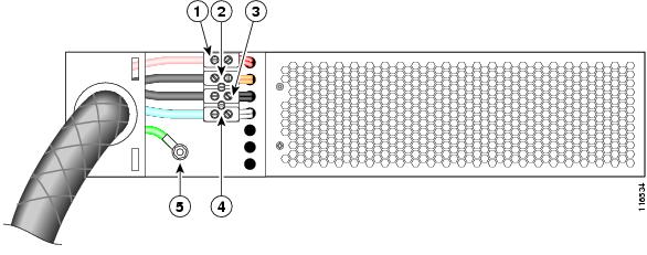
|
1 |
Lead 1 (L1) |
4 |
Lead 4 (L4—neutral) |
|
2 |
Lead 2 (L2) |
5 |
Ground |
|
3 |
Lead 3 (L3) |
|
|
Note | Leads 1, 2 and 3 (L1, L2, and L3) are not associated with any particular color of cable conductor because they are not connected to neutral (L4) or the safety ground (5). |
Note | We recommend that you rotate the L1, L2, and L3 wiring connection for the two power shelves to improve system availability due to common phase outage. |
Note | The ground cable conductor connector nuts have a 20 in-lb (2.26 N-m) torque value, and the power cable conductor connector screws on the terminal block have a 9 in-lb (1.04 N-m) torque value. |
AC Delta Power Shelf Cord
The AC Delta power shelf arrives with a 4-wire Delta cord with an IEC 60309 plug rated 250 V/60 A, IP67, 3W+PE; it is 4 meters long. The power shelf has four corresponding terminations: three active (“hot”) and one ground. The ground lug and terminal block are located behind a removable cover on the rear of the power shelf. The terminal block contains three terminations to attach the three active cable conductors from the input power cord. The ground cable conductor from the input power cord is attached to the ground lug.
The rear of the AC Delta power shelf is shown in this figure:
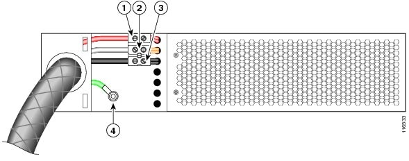
|
1 |
Lead 1 (L1) |
3 |
Lead 3 (L3) |
|
2 |
Lead 2 (L2) |
4 |
Ground |
Note | L1, L2, and L3 are not associated with any particular color of cable conductor as long as they are not connected to neutral or the safety ground (4). |
Note | We recommend that you rotate the L1, L2, and L3 wiring connection for the two power shelves to improve system availability due to common phase outage. |
Note | The ground cable conductor connector screws have a 20 in-lb (2.26 N-m) torque value, and the power cable conductor connector screws on the terminal block have a 9 in-lb (1.04 N-m) torque value. |
Steps
To wire a fixed configuration AC Wye or AC Delta power shelf, perform the following steps:
1. Attach the ESD-preventive wrist strap to your wrist and connect its leash to one of the ESD connection sockets on the front (SFC) side of the chassis or a bare metal surface on the chassis.
2. For AC Wye only, choose your neutral cable conductor; white is usually neutral. Be sure to perform a continuity check with a volt meter to verify that the neutral pin (labeled with an “N” on the plug) is connected to the neutral cable conductor.
3. Remove the rear cover from the power shelf.
4. The shelf arrives with two wiring holes for the power cable. Choose the wiring hole for your cable and remove the knock-out plug, if needed.
5. Ensure that the insulating layer has been removed from the cable conductor ends.
6. Insert the AC power cord and tighten the cable bushing lock nut.
7. Remove the M6 nut from ground connection (green cable conductor is typically ground), attach the ground cable conductor, and tighten the nut (ground cable conductor has a closed-ring connector) to a torque value of 20 in-lb (2.26 N-m).
8. For AC Wye only, connect the neutral cable conductor to the terminal block by backing out the left side terminal block screw, inserting the cable conductor, and tightening the screw to a torque value of 9 in-lbs (1.04 N-m). Do not loosen the screw on the right side of the terminal block.
9. Connect the other three active cable conductors in the same way as the neutral cable conductor. Back out the left side terminal block screw, insert the cable conductor, and tighten the screw to a torque value of 9 in-lbs (1.04 N-m). Do not loosen the screw on the right side of the terminal block.
DETAILED STEPS
| Step 1 | Attach the ESD-preventive wrist strap to your wrist and connect its leash to one of the ESD connection sockets on the front (SFC) side of the chassis or a bare metal surface on the chassis. | ||
| Step 2 | For AC Wye only, choose your neutral cable conductor; white is usually neutral. Be sure to perform a continuity check with a volt meter to verify that the neutral pin (labeled with an “N” on the plug) is connected to the neutral cable conductor. | ||
| Step 3 | Remove the rear cover from the power shelf. | ||
| Step 4 | The shelf arrives with two wiring holes for the power cable. Choose the wiring hole for your cable and remove the knock-out plug, if needed. | ||
| Step 5 | Ensure that the insulating layer has been removed from the cable conductor ends. | ||
| Step 6 | Insert the AC power cord and tighten the cable bushing lock nut. | ||
| Step 7 | Remove the M6 nut from ground connection (green cable conductor is typically ground), attach the ground cable conductor, and tighten the nut (ground cable conductor has a closed-ring connector) to a torque value of 20 in-lb (2.26 N-m). | ||
| Step 8 | For AC Wye
only, connect the neutral cable conductor to the terminal block by backing out
the left side terminal block screw, inserting the cable conductor, and
tightening the screw to a torque value of 9 in-lbs (1.04 N-m). Do not loosen
the screw on the right side of the terminal block.
| ||
| Step 9 | Connect the other three active cable conductors in the same way as the neutral cable conductor. Back out the left side terminal block screw, insert the cable conductor, and tighten the screw to a torque value of 9 in-lbs (1.04 N-m). Do not loosen the screw on the right side of the terminal block. |
What to Do Next
After performing this task, the AC rectifiers can be installed. See the c_Installing_an_AC_Rectifier_or_DC_PEM_1069591.xml for more information.
Removing Fixed Configuration AC Power Shelf Wiring
This section describes how to remove the AC Wye and AC Delta power shelf cords in the fixed configuration power system.
For additional power shelf details, see Cisco CRS Series Carrier Routing System Description or Cisco CRS-1 Carrier Routing System Fabric Card Chassis Specifications chapter.
Prerequisites
Before performing this task, power down and remove the AC rectifiers and the alarm module from the shelf you want to disconnect. Remove the upper grille on the rear (OIM) side of the chassis, if installed.
Note | Before removing AC power cords from the power shelf, make sure that the input power cords are not energized. |
Required Tools and Equipment
You need the following tools to perform this task:
- ESD-preventive wrist strap
- 3/8-in. ratchet wrench with 10-mm socket
- 1/4-in. x 6-in. long slotted screwdriver
AC Wye Power Shelf Cords
The rear of the AC Wye power shelf is shown in this figure.
|
1 |
Lead 1 (L1) |
4 |
Lead 4 (L4, neutral) |
|
2 |
Lead 2 (L2) |
5 |
Ground |
|
3 |
Lead 3 (L3) |
|
|
Note | Leads 1, 2, and 3 (L1, L2, and L3) are not associated with any particular color of cable conductor because they are not connected to neutral (L4) or the safety ground (5). |
Note | When removing AC power cords from the fixed configuration power shelf, be sure to remove the ground cable conductor last. |
AC Delta Power Shelf Cords
The rear of the AC Delta power shelf is shown in this figure.
|
1 |
Lead 1 (L1) |
3 |
Lead 3 (L3) |
|
2 |
Lead 2 (L2) |
4 |
Ground |
Note | Leads 1, 2, and 3 (L1, L2, and L3) are not associated with any particular color of cable conductor because they are not connected to neutral or the safety ground (4). |
Note | When removing AC cords from the fixed configuration power shelf, be sure to remove the ground cable conductor last. |
Steps
To disconnect the power cord from the fixed configuration AC Wye or AC Delta power shelf, perform the following steps:
1. Attach the ESD-preventive wrist strap to your wrist and connect its leash to one of the ESD connection sockets on the front (SFC) side of the chassis or a bare metal surface on the chassis.
2. Disconnect the three active cable conductors by loosening the screw on the left side of the terminal block for each cable conductor and removing the cable conductor.
3. For AC Wye only, disconnect the neutral cable conductor by backing out the left side terminal block screw and removing the cable conductor. White is usually neutral.
4. Remove the M6 nut from the ground connection (green is typically the ground cable conductor) and remove the ground cable conductor.
DETAILED STEPS
| Step 1 | Attach the ESD-preventive wrist strap to your wrist and connect its leash to one of the ESD connection sockets on the front (SFC) side of the chassis or a bare metal surface on the chassis. | ||
| Step 2 | Disconnect the
three active cable conductors by loosening the screw on the left side of the
terminal block for each cable conductor and removing the cable conductor.
| ||
| Step 3 | For AC Wye only, disconnect the neutral cable conductor by backing out the left side terminal block screw and removing the cable conductor. White is usually neutral. | ||
| Step 4 | Remove the M6 nut from the ground connection (green is typically the ground cable conductor) and remove the ground cable conductor. |
What to Do Next
After performing this task, the power shelf can be removed. For more information, see the Removing a Fixed Configuration Power Shelf section.
Installing Fixed Configuration DC Power Shelf Wiring
This section describes how to install the DC wiring on the fixed configuration DC power shelf. This figure shows the cable wiring on the rear of the FCC fixed configuration DC power shelf.
|
1 |
PEM O, input 1 |
5 |
Input-power-present LEDs |
|
2 |
PEM 0, input 2 |
6 |
Ground lug nuts |
|
3 |
PEM 1, input 3 |
7 |
Terminal block covers |
|
4 |
PEM 1, input 4 |
|
|
For additional power shelf details, see Cisco CRS Series Carrier Routing System Description or Appendix 1, “Cisco CRS-1 Carrier Routing System Fabric Card Chassis Specifications” .
Note | When wiring the power shelf, be sure to connect the ground cable first. |
Prerequisites
Before performing this task, ensure that both power shelves are installed in the chassis. Remove the upper grille on the rear (OIM) side of the chassis, if installed.
Note | Before installing wiring on the power shelf, make sure that the input power cables are not energized. |
Note | If the cables are wrapped with black electrical tape, be sure to remove tape from the cables before installing cabling on the power shelf. |
Required Tools and Equipment
You need the following tools to perform this task:
- ESD-preventive wrist strap
- 3/8 in. ratchet wrench with 10-mm socket
- Crimping tool and lug specific die
- Multimeter
- Torque wrench with 10-mm 6 pt. socket and rated accuracy at 30 in.-lb (2.26 N-m)
- Torque wrench with 10-mm 6 pt. socket and rated accuracy at 20 in.-lb (2.26 N-m)
Steps
To wire the fixed configuration DC power shelf, perform the following steps:
1. Attach the ESD-preventive wrist strap to your wrist and connect its leash to one of the ESD connection sockets on the front (SFC) side of the chassis or a bare metal surface on the chassis.
2. Remove the terminal block cover.
3. Verify the following resistance values:
4. Use the crimping tool mandated by the lug manufacturer to crimp the lugs to the DC-input cables and the power shelf grounding cable. For details on lugs, see the c_DC_Power_Systems_1062204.xml.
5. Using a 10-mm socket wrench, attach the ground cable to the ground cable terminal. Then use the torque wrench to tighten to a torque of 30 in.-lb (3.39 N-m).
6. Using the wrench, attach the positive and negative cables to each terminal block. Then use the torque wrench to tighten to a torque of 20 in.-lb (2.26 N-m).
7. Reattach the terminal cover with a phillips screwdriver. Insert and tighten the screw holding the cover to the wiring terminal block.
DETAILED STEPS
| Step 1 | Attach the ESD-preventive wrist strap to your wrist and connect its leash to one of the ESD connection sockets on the front (SFC) side of the chassis or a bare metal surface on the chassis. | ||
| Step 2 | Remove the terminal block cover. | ||
| Step 3 | Verify the
following resistance values:
| ||
| Step 4 | Use the
crimping tool mandated by the lug manufacturer to crimp the lugs to the
DC-input cables and the power shelf grounding cable. For details on lugs, see
the
c_DC_Power_Systems_1062204.xml.
The cable should be sized according to local and national installation requirements. Use only copper cable.
| ||
| Step 5 | Using a 10-mm socket wrench, attach the ground cable to the ground cable terminal. Then use the torque wrench to tighten to a torque of 30 in.-lb (3.39 N-m). | ||
| Step 6 | Using the wrench, attach the positive and negative cables to each terminal block. Then use the torque wrench to tighten to a torque of 20 in.-lb (2.26 N-m). | ||
| Step 7 | Reattach the terminal cover with a phillips screwdriver. Insert and tighten the screw holding the cover to the wiring terminal block. |
What to Do Next
After the power shelf wiring has been connected, the DC PEMs can be installed. For more information, see the c_Installing_an_AC_Rectifier_or_DC_PEM_1069591.xml.
Removing Fixed Configuration DC Power Shelf Wiring
This section describes how to remove the DC power shelf wiring from the fixed configuration power shelf.
For additional power shelf details, see Cisco CRS Series Carrier Routing System Description or appendix titled Cisco CRS-1 Carrier Routing System Fabric Card Chassis Specifications.
Note | When removing DC wiring from the fixed configuration power shelf, be sure to remove the ground cable last. |
Prerequisites
Before performing this task, power down and remove the DC PEMs and the alarm module from the shelf you want to disconnect. Remove the upper grille on the rear (OIM) side of the chassis, if installed.
Note | Before removing wiring from the power shelf, make sure that the input power cables are not energized. |
Required Tools and Equipment
You need the following tools to perform this task:
- ESD-preventive wrist strap
- 3/8-in. ratchet wrench with 10-mm socket
Steps
To disconnect wiring from the fixed configuration DC power shelf, perform the following steps:
1. Attach the ESD-preventive wrist strap to your wrist and connect its leash to one of the ESD connection sockets on the front (SFC) side of the chassis or a bare metal surface on the chassis.
2. Remove the terminal block cover
3. Using the 10-mm socket wrench, remove the positive and negative cables from each terminal block.
4. Using the wrench, remove the ground cable from the ground cable terminal.
5. Replace the terminal block covers.
DETAILED STEPS
| Step 1 | Attach the ESD-preventive wrist strap to your wrist and connect its leash to one of the ESD connection sockets on the front (SFC) side of the chassis or a bare metal surface on the chassis. | ||
| Step 2 | Remove the terminal block cover | ||
| Step 3 | Using the 10-mm socket wrench, remove the positive and negative cables from each terminal block. | ||
| Step 4 | Using the
wrench, remove the ground cable from the ground cable terminal.
| ||
| Step 5 | Replace the terminal block covers. |
What to Do Next
After the power shelf wiring has been disconnected, the power shelf can be removed. For more information, see the Removing a Fixed Configuration Power Shelf section.
Installing an AC Rectifier or DC PEM
This section describes how to install an AC rectifier or DC PEM in a fixed configuration power shelf in the FCC. For information on the power types, see the c_DC_Power_Systems_1062204.xml and the c_AC_Power_Systems_1311127.xml. For complete information on regulatory compliance and safety, see Cisco CRS Carrier Routing System Regulatory Compliance and Safety Information.
The power module is installed into the power shelf on the front (SFC) side of the chassis. Although differences exist among the AC rectifiers and DC PEMs (AC Wye, AC Delta, and DC), they are installed in the same manner. This figure shows an AC rectifier for reference. The fixed configuration DC PEM is similar.
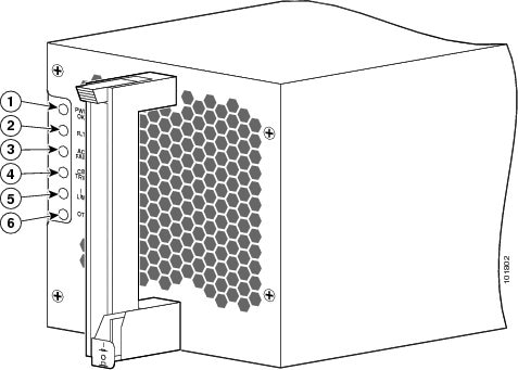
|
1 |
PWR OK |
4 |
CBREAKER TRIP |
|
2 |
FLT |
5 |
ILIM |
|
3 |
AC INPUT FAIL |
6 |
OT |
Prerequisites
Before performing this task, you must first remove the upper grille on the front (SFC) side of the chassis, if installed.
Required Tools and Equipment
You need the following tool and part to perform this task:
- ESD-preventive wrist strap
-
Fixed configuration AC rectifier or DC PEM
- AC rectifier Cisco product number CRS16-AC-RECT=
- DC PEM Cisco product number CRS16-DC-PEM=)
Steps
To install an AC rectifier or DC PEM in a fixed configuration power shelf, perform the following steps:
1. Attach the ESD-preventive wrist strap to your wrist and connect its leash to one of the ESD connection sockets on the front (SFC) side of the chassis or a bare metal surface on the chassis.
2. Turn the power switch to the OFF position.
3. While facing the front (SFC) side of the chassis, press the ejector lever release button at the top of the AC rectifier or DC PEM to release the ejector lever.
4. Pivot the ejector lever away from the module faceplate.
5. Using two hands to support and guide the AC rectifier or DC PEM, slide it into the power system shelf until the connector on the back of the module just makes contact with the connector on the backplane of the power shelf.
6. Seat the power module in the power shelf backplane by pivoting the ejector lever to hook the slot on the floor of the power shelf and then pushing the ejector lever until it is flush with the power module faceplate. You hear a click when the ejector lever locks into place.
7. Push the power tab at the bottom front of the power module in to the ON position.
DETAILED STEPS
| Step 1 | Attach the ESD-preventive wrist strap to your wrist and connect its leash to one of the ESD connection sockets on the front (SFC) side of the chassis or a bare metal surface on the chassis. | ||||
| Step 2 | Turn the power switch to the OFF position. | ||||
| Step 3 | While facing the front (SFC) side of the chassis, press the ejector lever release button at the top of the AC rectifier or DC PEM to release the ejector lever. | ||||
| Step 4 | Pivot the ejector lever away from the module faceplate. | ||||
| Step 5 | Using two hands
to support and guide the AC rectifier or DC PEM, slide it into the power system
shelf until the connector on the back of the module just makes contact with the
connector on the backplane of the power shelf.
| ||||
| Step 6 | Seat the power module in the power shelf backplane by pivoting the ejector lever to hook the slot on the floor of the power shelf and then pushing the ejector lever until it is flush with the power module faceplate. You hear a click when the ejector lever locks into place. | ||||
| Step 7 | Push the power tab at the bottom front of the power module in to the ON position. |
What to Do Next
After performing this task, replace the upper grille on the front (SFC) side of the chassis.
Removing an AC Rectifier or DC PEM
This section describes how to remove an AC rectifier or DC PEM from the FCC. For information on the power types, see the c_DC_Power_Systems_1062204.xml and the c_AC_Power_Systems_1311127.xml. For complete information on regulatory compliance and safety, see Cisco CRS Carrier Routing System Regulatory Compliance and Safety Information.
Although differences exist among the AC rectifiers and DC PEMs (AC Wye, AC Delta, and DC), they are removed in the same manner. Figure 1 shows a DC PEM for reference.
Prerequisites
Before performing this task, you must first remove the upper grille on the front (SFC) side of the chassis, if installed.
Required Tools and Equipment
You need the following tool to perform this task:
- ESD-preventive wrist strap
Steps
To remove an AC rectifier or DC PM from a fixed configuration power shelf, perform the following steps:
1. Attach the ESD-preventive wrist strap to your wrist and connect its leash to one of the ESD connection sockets on the front (SFC) side of the chassis or a bare metal surface on the chassis.
2. While facing the front (SFC) side of the chassis, pull the power tab at the bottom front of the module out to the OFF position.
3. Press the ejector lever release button at the top of the power module to release the ejector lever.
4. Pivot the ejector lever away from the power module faceplate to eject the module from the power shelf backplane connector.
5. Grasp the power module handle and pull the module halfway from the bay. Be sure not to pull the module by the ejector lever, but rather by the handle only.
6. Be sure to support the module while you slide the module completely from the bay.
7. Set the power module carefully aside.
DETAILED STEPS
| Step 1 | Attach the ESD-preventive wrist strap to your wrist and connect its leash to one of the ESD connection sockets on the front (SFC) side of the chassis or a bare metal surface on the chassis. | ||
| Step 2 | While facing the front (SFC) side of the chassis, pull the power tab at the bottom front of the module out to the OFF position. | ||
| Step 3 | Press the ejector lever release button at the top of the power module to release the ejector lever. | ||
| Step 4 | Pivot the
ejector lever away from the power module faceplate to eject the module from the
power shelf backplane connector.
| ||
| Step 5 | Grasp the power
module handle and pull the module halfway from the bay. Be sure not to pull the
module by the ejector lever, but rather by the handle only.
| ||
| Step 6 | Be sure to support the module while you slide the module completely from the bay. | ||
| Step 7 | Set the power module carefully aside. |
What to Do Next
After performing this task, install a replacement AC Rectifier or DC PEM if necessary (see the c_Installing_an_AC_Rectifier_or_DC_PEM_1069591.xml) and replace the upper grille on the front (SFC) side of the chassis.
Installing a Fixed Configuration Alarm Module
This section describes how to install an alarm module in a fixed configuration power shelf in the FCC. An alarm module can be installed only in the far right slot of the power shelf (as you are facing the front [SFC] side of the chassis). For complete information on regulatory compliance and safety, see Cisco CRS Carrier Routing System Regulatory Compliance and Safety Information.
Each AC or DC power shelf contains an alarm module, which monitors the status of the power shelf and provides an external interface for system alarms. A dedicated alarm module slot exists on the right side of each fixed configuration power shelf. The same alarm module is used in all fixed configuration power shelves.
This figure shows a fixed configuration alarm module.
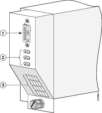
|
1 |
External alarm connector |
3 |
LED display |
|
2 |
Alarm LEDs |
|
|
Prerequisites
Before performing this task, you must first remove the upper grille on the front (SFC) side of the chassis, if installed.
Required Tools and Equipment
You need the following tools and part to perform this task:
- ESD-preventive wrist strap
- 6-in long number 1 Phillips screwdriver
- Fixed configuration alarm module (Cisco product number CRS-16-ALARM=)
Steps
To install a fixed configuration alarm module, perform the following steps:
1. Attach the ESD-preventive wrist strap to your wrist and connect its leash to one of the ESD connection sockets on the front (SFC) side of the chassis or a bare metal surface on the chassis.
2. Using two hands to support and guide the alarm module, slide it into the far right bay on the power shelf (as you face the front [SFC] side of the chassis) until the connector on the back of the alarm module just makes contact with the connector on the backplane of the power shelf. Verify that the guide pin on the chassis front panel is correctly aligned with the hole on the front of the alarm module.
3. Seat the alarm module in the power shelf backplane by pressing it firmly to the power shelf backplane connector.
4. Use the Phillips screwdriver to turn the captive screw at the bottom of the alarm module clockwise to seat the alarm module connectors in the connectors on the power shelf interface panel.
DETAILED STEPS
| Step 1 | Attach the
ESD-preventive wrist strap to your wrist and connect its leash to one of the
ESD connection sockets on the front (SFC) side of the chassis or a bare metal
surface on the chassis.
| ||
| Step 2 | Using two hands
to support and guide the alarm module, slide it into the far right bay on the
power shelf (as you face the front [SFC] side of the chassis) until the
connector on the back of the alarm module just makes contact with the connector
on the backplane of the power shelf. Verify that the guide pin on the chassis
front panel is correctly aligned with the hole on the front of the alarm
module.
| ||
| Step 3 | Seat the alarm module in the power shelf backplane by pressing it firmly to the power shelf backplane connector. | ||
| Step 4 | Use the Phillips screwdriver to turn the captive screw at the bottom of the alarm module clockwise to seat the alarm module connectors in the connectors on the power shelf interface panel. |
What to Do Next
After performing this task, replace the upper grille on the front (SFC) side of the chassis.
Removing a Fixed Configuration Alarm Module
This section describes how to remove an alarm module from a fixed configuration power shelf in the FCC. The alarm module is installed only in the far right slot of the power shelf (as our are facing the front [SFC] side of the chassis. For complete information on regulatory compliance and safety, see Regulatory Compliance and Safety Information for the Cisco CRS Carrier Routing System.
Figure 1 shows a fixed configuration alarm module.
Prerequisites
Before performing this task, you must first remove the upper grille on the front (SFC) side of the chassis, if installed.
Required Tools and Equipment
You need the following tools to perform this task:
- ESD-preventive wrist strap
- 6-in long number 1 Phillips screwdriver
Steps
To remove an alarm module, perform the following steps:
1. Attach the ESD-preventive wrist strap to your wrist and connect its leash to one of the ESD connection sockets on the front (SFC) side of the chassis or a bare metal surface on the chassis.
2. Use the screwdriver to loosen the captive screw that fastens the alarm module to the front (SFC) side of the chassis.
3. Grasp the alarm module and pull it halfway from the bay.
4. Use your free hand to support the alarm module while you slide the alarm module completely from the bay.
5. Set the alarm module carefully aside.
DETAILED STEPS
| Step 1 | Attach the ESD-preventive wrist strap to your wrist and connect its leash to one of the ESD connection sockets on the front (SFC) side of the chassis or a bare metal surface on the chassis. | ||
| Step 2 | Use the screwdriver to loosen the captive screw that fastens the alarm module to the front (SFC) side of the chassis. | ||
| Step 3 | Grasp the alarm
module and pull it halfway from the bay.
| ||
| Step 4 | Use your free hand to support the alarm module while you slide the alarm module completely from the bay. | ||
| Step 5 | Set the alarm module carefully aside. |
What to Do Next
After performing this task, install a replacement alarm module (if necessary) and replace the upper grille on the front (SFC) side of the chassis.
Powering Up and Down a Chassis with Fixed Configuration AC Power
This section describes how to power up and power down an FCC with fixed configuration AC power shelves installed. For details on the fixed configuration AC power system, see the c_AC_Power_Systems_1311127.xml. For complete information on regulatory compliance and safety, see Regulatory Compliance and Safety Information for the Cisco CRS Carrier Routing System .
Each power shelf in the FCC has its own I/O switch for shelf power cutoff. Power shelf linkage cuts power to the chassis as a whole when both power shelves are turned off.
Most components on the chassis, including the power shelves, power modules, alarm modules, and fan trays, can be removed or installed in the chassis while it is running. Although it is possible to install or remove a power shelf while the chassis is running, it is recommended to remove power from the chassis completely, if possible, for service protection and safety.
Note | While the chassis can be powered on by switching on the power shelf I/O switch (if all individual power rectifier power switches are in the on position), this method draws a large power surge on start-up. We recommend following the procedure outlined below to power the chassis on and off. |
This figure shows the Front (SFC) side of the FCC with fixed configuration power installed.
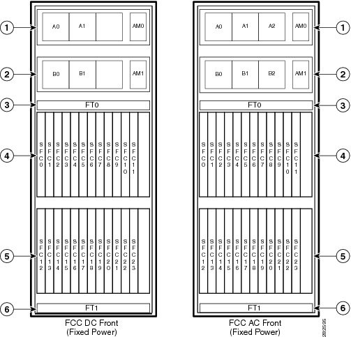
|
1 |
Power shelf PS0 |
4 |
Upper card cage |
|
2 |
Power shelf PS1 |
5 |
Lower card cage |
|
3 |
Fan tray FT0 |
6 |
Fan tray FT1 |
Prerequisites
Before performing this task, you must install and wire the power shelves, and install the AC rectifiers, alarm modules, SCGE cards, and exterior cosmetic components. See the c_Installing_a_Fixed_Configuration_Power_Shelf_1189509.xml, the c_Installing_Fixed_Configuration_AC_Power_Shelf_Cord_1177594.xml or c_Installing_Fixed_Configuration_DC_Power_Shelf_Wiring_1193289.xml, the c_Installing_an_AC_Rectifier_or_DC_PEM_1069591.xml, the c_Installing_a_Fixed_Configuration_Alarm_Module_1069674.xml, and Installing and Removing Exterior Cosmetic Components chapter for more information.
Required Tools and Equipment
You need the following tools to perform this task:
- ESD-preventive wrist strap
- Multimeter
- 1/4-in. x 6-in. long slotted screwdriver
Steps
To power on the chassis, perform the following steps:
1. Attach the ESD-preventive wrist strap to your wrist and connect its leash to one of the ESD connection sockets on the front (SFC) side of the chassis or a bare metal surface on the chassis.
2. Make sure that the safety ground wiring is connected.
3. Make sure that the facility power breakers for the upper (PS0) and lower (PS1)power shelves are in the OFF position.
4. Make sure that all the I/O switches are in the OFF position. That is, make sure all I/O levers are pulled out. There are total of six I/O levers for the AC power rectifiers (one for each of the six AC rectifiers) and two I/O levers for the AC power shelves (one for each power shelf).
5. Make sure all SFCs are pulled-out and disconnected from the backplane.
6. Remove the cover plate from the rear of the AC power shelves.
7. Plug in AC power cords.
8. For AC Delta and AC wye, verify the following resistance values (see Figure 1 and Figure 1):
9. Make sure that each input power cable is connected, and energize the facility breaker to each input.
10. Measure the voltage between the following:
11. Turn the facility breaker for the upper power shelf (PS0) to the OFF position. Repeat for the facility power breaker for the lower power shelf (PS1).
12. Turn the facility breaker for the upper power shelf (PS0) to the ON position. Repeat for the facility power breaker for the lower power shelf (PS1).
13. Turn the power shelf I/O switches on both power shelves (PS0 and PS1) to the ON position. Verify that the “CBREAKER TRIP” LED on the front panel of each power rectifier is yellow and that no other LEDs are active.
14. Turn the first power rectifier (A0; see Figure 1) power switch on the upper power shelf (PS0) to the ON position. Verify that the “PWR OK” LED on the power rectifier (A0) front panel is green and that no other LEDs are active. Repeat for the other two rectifiers (A1 and A2; see Figure 1).
15. Turn the first power rectifier (B0; see Figure 1) I/O switch on the lower power shelf (PS1) to the ON position. Verify that the “PWR OK” LED on the power rectifier (B0) front panel is green and that no other LEDs are active. Repeat for the other two rectifiers (B1 and B2; see Figure 1).
16. Turn the I/O switches on all power rectifiers and both power shelves to the OFF position. Verify that no LEDs on the power rectifier front panels are active.
17. Insert all boards into the chassis (see Installing and Removing Fabric Cards and Card Components chapter).
18. Turn the power shelf I/O switches (PS0 and PS1) to the ON position.
19. Turn all power rectifier I/O switches to the ON position.
20. Measure the input voltage of each input and compare this value to the voltage measurement noted in step 7. Verify that the voltage is between 200 to 240 VAC, ensure that the voltage drop is within the acceptable limits for your site.
21. Turn the I/O switches on all power rectifiers and both power shelves to the OFF position. Turn the facility breaker for the upper power shelf (PS0) to the OFF position. Repeat for the facility power breaker for the lower power shelf (PS1).
22. Replace the cover plate on the rear of the AC power shelves.
23. Turn the facility breaker for the upper power shelf (PS0) to the ON position. Repeat for the facility power breaker for the lower power shelf (PS1).
24. Turn both power shelf I/O switches (PS0 and PS1) to the ON position. Turn all power rectifier I/O switches to the ON position.
DETAILED STEPS
| Step 1 | Attach the ESD-preventive wrist strap to your wrist and connect its leash to one of the ESD connection sockets on the front (SFC) side of the chassis or a bare metal surface on the chassis. |
| Step 2 | Make sure that the safety ground wiring is connected. |
| Step 3 | Make sure that the facility power breakers for the upper (PS0) and lower (PS1)power shelves are in the OFF position. |
| Step 4 | Make sure that all the I/O switches are in the OFF position. That is, make sure all I/O levers are pulled out. There are total of six I/O levers for the AC power rectifiers (one for each of the six AC rectifiers) and two I/O levers for the AC power shelves (one for each power shelf). |
| Step 5 | Make sure all SFCs are pulled-out and disconnected from the backplane. |
| Step 6 | Remove the cover plate from the rear of the AC power shelves. |
| Step 7 | Plug in AC power cords. |
| Step 8 | For AC Delta
and AC wye, verify the following resistance values (see
Figure 1
and
Figure 1):
For AC Wye only, verify the following resistance values:
|
| Step 9 | Make sure that each input power cable is connected, and energize the facility breaker to each input. |
| Step 10 | Measure the
voltage between the following:
Verify that the AC voltage is between 200 to 240 VAC. Make a note of this voltage measurement. |
| Step 11 | Turn the facility breaker for the upper power shelf (PS0) to the OFF position. Repeat for the facility power breaker for the lower power shelf (PS1). |
| Step 12 | Turn the facility breaker for the upper power shelf (PS0) to the ON position. Repeat for the facility power breaker for the lower power shelf (PS1). |
| Step 13 | Turn the power shelf I/O switches on both power shelves (PS0 and PS1) to the ON position. Verify that the “CBREAKER TRIP” LED on the front panel of each power rectifier is yellow and that no other LEDs are active. |
| Step 14 | Turn the first power rectifier (A0; see Figure 1) power switch on the upper power shelf (PS0) to the ON position. Verify that the “PWR OK” LED on the power rectifier (A0) front panel is green and that no other LEDs are active. Repeat for the other two rectifiers (A1 and A2; see Figure 1). |
| Step 15 | Turn the first power rectifier (B0; see Figure 1) I/O switch on the lower power shelf (PS1) to the ON position. Verify that the “PWR OK” LED on the power rectifier (B0) front panel is green and that no other LEDs are active. Repeat for the other two rectifiers (B1 and B2; see Figure 1). |
| Step 16 | Turn the I/O switches on all power rectifiers and both power shelves to the OFF position. Verify that no LEDs on the power rectifier front panels are active. |
| Step 17 | Insert all boards into the chassis (see Installing and Removing Fabric Cards and Card Components chapter). |
| Step 18 | Turn the power shelf I/O switches (PS0 and PS1) to the ON position. |
| Step 19 | Turn all power rectifier I/O switches to the ON position. |
| Step 20 | Measure the input voltage of each input and compare this value to the voltage measurement noted in step 7. Verify that the voltage is between 200 to 240 VAC, ensure that the voltage drop is within the acceptable limits for your site. |
| Step 21 | Turn the I/O switches on all power rectifiers and both power shelves to the OFF position. Turn the facility breaker for the upper power shelf (PS0) to the OFF position. Repeat for the facility power breaker for the lower power shelf (PS1). |
| Step 22 | Replace the cover plate on the rear of the AC power shelves. |
| Step 23 | Turn the facility breaker for the upper power shelf (PS0) to the ON position. Repeat for the facility power breaker for the lower power shelf (PS1). |
| Step 24 | Turn both power shelf I/O switches (PS0 and PS1) to the ON position. Turn all power rectifier I/O switches to the ON position. |
What to Do Next
Note | For appropriate SFC LED information, see the appropriate section in Installing and Removing Fabric Cards and Card Components chapter or the specific documentation for the card. |
To power down the chassis entirely, you must power down both of the power shelves by moving the power shelf I/O switch to the OFF position by lifting up on the lever and pulling it out. Both power shelves must be disconnected to de-energize the chassis completely.
Note | All AC power cords must be de-energized to fully remove power from the chassis. |
This table shows the meaning of the LED status lights on the front panel of the AC power rectifiers in the fixed configuration power system.
|
LED Name |
Color |
Function or Meaning |
|---|---|---|
|
PWR OK |
Green |
Rectifier module is operating normally in a powered-up condition |
|
FLT |
Yellow |
A fault has been detected in the rectifier |
|
AC INPUT FAIL |
Yellow |
The AC is out of range or the rectifier is not receiving AC power input |
|
CBREAKER TRIP |
Yellow |
Rectifier I/O switch is in the OFF position |
|
OT |
Yellow |
Rectifier is in an over-temperature condition and a shutdown has occurred |
|
ILIM |
Yellow |
Rectifier is operating in a current limit condition |
Powering Up and Down a Chassis with Fixed Configuration DC Power
This section describes how to power up and power down an FCC with fixed configuration DC power shelves installed. For details on the chassis power systems, see the c_DC_Power_Systems_1062204.xml. For complete information on regulatory compliance and safety, see Regulatory Compliance and Safety Information for the Cisco CRS Carrier Routing System.
Each power shelf in the FCC has its own I/O switch for shelf power cutoff; the FCC as a whole does not have a single power switch that powers the entire chassis and all its components up and down. Power shelf linkage cuts power to the chassis as a whole when both power shelves are turned off.
Most components on the chassis, including the power shelves, power modules, alarm modules, and fan trays, can be removed or installed in the chassis while it is running. Although it is possible to install or remove a power shelf while the chassis is running, it is recommended to remove power from the chassis completely, if possible, for service protection and safety.
Note | Although the chassis can be powered on by switching on the two power shelf I/O switches (if all individual PEM power switches are in the ON position), this method draws a large power surge on start-up. We recommend following the procedure outlined below to power the chassis on and off. |
Prerequisites
Before performing this task, you must install and wire the power shelves, and install the DC PEMs, alarm modules, SCGE cards, and exterior cosmetic components. See thec_Installing_a_Fixed_Configuration_Power_Shelf_1189509.xml, the c_Installing_Fixed_Configuration_AC_Power_Shelf_Cord_1177594.xml or c_Installing_Fixed_Configuration_DC_Power_Shelf_Wiring_1193289.xml,the c_Installing_an_AC_Rectifier_or_DC_PEM_1069591.xml, the c_Installing_a_Fixed_Configuration_Alarm_Module_1069674.xml, the Installing an SCGE Card section and Installing and Removing Exterior Cosmetic Components chapter for more information. Wiring at the BDFB or at the power plant should be complete.
Required Tools and Equipment
You need the following tools to perform this task:
- ESD-preventive wrist strap
- Multimeter
Steps
To power on the chassis, perform the following steps:
1. Attach the ESD-preventive wrist strap to your wrist and connect its leash to one of the ESD connection sockets on the front (SFC) side of the chassis or a bare metal surface on the chassis.
2. Verify that the safety ground wiring is connected to the upper and lower power shelves.
3. Make sure that the facility power breakers for the upper (PS0) and lower (PS1) power shelves are in the OFF position.
4. Make sure that all the I/O switches are in the OFF position. That is, make sure all I/O levers are pulled out. There are total of four I/O levers for the DC PEMs (one for each of the four DC PEMs) and two I/O levers for the DC power shelves (one for each power shelf).
5. Make sure all SFCs are pulled-out and disconnected from the backplane.
6. Energize the facility breaker to PEM 0, input 1 on the upper power shelf, PS0.
7. Measure the voltage at the input terminal block and verify that the DC voltage between the positive and negative terminals is between 48 VDC and 60 VDC. Make a note of this voltage measurement.
8. Turn the facility breaker to the OFF position.
9. Repeat steps 7 through 9 for each of the remaining three DC inputs on the upper power shelf, PS0.
10. Repeat steps 7 through 9 for each of the four DC inputs on the lower power shelf, PS1.
11. Turn the facility power breakers for the upper power shelf, PS0, to the ON position. Repeat for the lower power shelf, PS1.
12. Turn the upper power shelf (PS0; see Figure 1) I/O switch to the ON position. Verify that the “CBREAKER TRIP” LED on the front panel of each DC PEM is yellow and that no other LEDs are active.
13. Turn the first PEM (A0; see Figure 1) I/O switch on the upper power shelf (PS0) to the ON position. Verify that the “PWR OK” LED on the front panel of the DC PEM is green and that no other LEDs are active. Repeat for the other DC PEM (A1; see Figure 1).
14. Turn the lower power shelf (PS1; see Figure 1) I/O switch to the ON position. Verify that the “CBREAKER TRIP” LED on the front panel of the DC PEM is yellow and that no other LEDs are active.
15. Turn the first DC PEM (B0; see Figure 1) I/O switch on the lower power shelf (PS1) to the ON position. Verify that the “PWR OK” LED on the front panel of the DC PEM is green and that no other LEDs are active. Repeat for the other DC PEM (B1; see Figure 1).
16. Turn the I/O switches on all PEMs and both power shelves to the OFF position. Verify that no LEDs on the PEM front panels are active.
17. Insert all boards into the chassis (see Installing and Removing Fabric Cards and Card Components chapter).
18. Turn the power shelf (PS0 and PS1) I/O switches to the ON position.
19. Turn all DC PEM I/O switches to the ON position.
20. Measure the input voltage of each input and compare this value to the voltage measurement noted in step 7. Verify that the equipment is still receiving the correct input voltage measured in step 7.
DETAILED STEPS
| Step 1 | Attach the ESD-preventive wrist strap to your wrist and connect its leash to one of the ESD connection sockets on the front (SFC) side of the chassis or a bare metal surface on the chassis. | ||||||||||||||||||||||||
| Step 2 | Verify that the safety ground wiring is connected to the upper and lower power shelves. | ||||||||||||||||||||||||
| Step 3 | Make sure that the facility power breakers for the upper (PS0) and lower (PS1) power shelves are in the OFF position. | ||||||||||||||||||||||||
| Step 4 | Make sure that all the I/O switches are in the OFF position. That is, make sure all I/O levers are pulled out. There are total of four I/O levers for the DC PEMs (one for each of the four DC PEMs) and two I/O levers for the DC power shelves (one for each power shelf). | ||||||||||||||||||||||||
| Step 5 | Make sure all SFCs are pulled-out and disconnected from the backplane. | ||||||||||||||||||||||||
| Step 6 | Energize the
facility breaker to PEM 0, input 1 on the upper power shelf, PS0.
| ||||||||||||||||||||||||
| Step 7 | Measure the voltage at the input terminal block and verify that the DC voltage between the positive and negative terminals is between 48 VDC and 60 VDC. Make a note of this voltage measurement. | ||||||||||||||||||||||||
| Step 8 | Turn the facility breaker to the OFF position. | ||||||||||||||||||||||||
| Step 9 | Repeat steps 7 through 9 for each of the remaining three DC inputs on the upper power shelf, PS0. | ||||||||||||||||||||||||
| Step 10 | Repeat steps 7 through 9 for each of the four DC inputs on the lower power shelf, PS1. | ||||||||||||||||||||||||
| Step 11 | Turn the facility power breakers for the upper power shelf, PS0, to the ON position. Repeat for the lower power shelf, PS1. | ||||||||||||||||||||||||
| Step 12 | Turn the upper power shelf (PS0; see Figure 1) I/O switch to the ON position. Verify that the “CBREAKER TRIP” LED on the front panel of each DC PEM is yellow and that no other LEDs are active. | ||||||||||||||||||||||||
| Step 13 | Turn the first PEM (A0; see Figure 1) I/O switch on the upper power shelf (PS0) to the ON position. Verify that the “PWR OK” LED on the front panel of the DC PEM is green and that no other LEDs are active. Repeat for the other DC PEM (A1; see Figure 1). | ||||||||||||||||||||||||
| Step 14 | Turn the lower power shelf (PS1; see Figure 1) I/O switch to the ON position. Verify that the “CBREAKER TRIP” LED on the front panel of the DC PEM is yellow and that no other LEDs are active. | ||||||||||||||||||||||||
| Step 15 | Turn the first DC PEM (B0; see Figure 1) I/O switch on the lower power shelf (PS1) to the ON position. Verify that the “PWR OK” LED on the front panel of the DC PEM is green and that no other LEDs are active. Repeat for the other DC PEM (B1; see Figure 1). | ||||||||||||||||||||||||
| Step 16 | Turn the I/O switches on all PEMs and both power shelves to the OFF position. Verify that no LEDs on the PEM front panels are active. | ||||||||||||||||||||||||
| Step 17 | Insert all boards into the chassis (see Installing and Removing Fabric Cards and Card Components chapter). | ||||||||||||||||||||||||
| Step 18 | Turn the power shelf (PS0 and PS1) I/O switches to the ON position. | ||||||||||||||||||||||||
| Step 19 | Turn all DC PEM
I/O switches to the ON position.
| ||||||||||||||||||||||||
| Step 20 | Measure the
input voltage of each input and compare this value to the voltage measurement
noted in step 7. Verify that the equipment is still receiving the correct input
voltage measured in step 7.
To power down the chassis entirely, you must power down both of the power shelves by moving the power shelf I/O switch to the OFF position by lifting up on the lever and pulling it out. Both power shelves must be disconnected to de-energize the chassis completely.
This table shows the meaning of the LED status lights on the DC PEMs.
|
Converting from One Fixed Configuration Power System to Another
To convert an FCC with a fixed configuration power system from AC to DC power, or from DC to AC power, perform the following steps:
1. Power down the chassis completely. See the c_Powering_Up_and_Down_a_Chassis_with_Fixed_Configuration_AC_Power_1090000.xml or the c_Powering_Up_and_Down_a_Chassis_with_Fixed_Configuration_DC_Power_1333123.xml for more information.
2. Remove the alarm modules. See the c_Removing_a_Fixed_Configuration_Alarm_Module_1069715.xml.
3. Remove the AC rectifiers or DC PEMs. See the c_Removing_an_AC_Rectifier_or_DC_PEM_1069631.xml.
4. Unplug the AC power cords or remove the DC fusing from the power source. Remove the AC or DC wiring from the rear of the fixed configuration power shelf. Remove the AC power cords or DC wiring and ground wire from the rear of the fixed configuration power shelves. See the c_Removing_Fixed_Configuration_AC_Power_Shelf_Wiring_1180533.xml and the c_Removing_Fixed_Configuration_DC_Power_Shelf_Wiring_1193337.xml.
5. Remove both power shelves. See the Removing a Fixed Configuration Power Shelf section.
6. Install the new power shelves. See the c_Installing_a_Fixed_Configuration_Power_Shelf_1189509.xml.
7. Install the wiring on the rear of the power shelf. See the c_Installing_Fixed_Configuration_AC_Power_Shelf_Cord_1177594.xml or the c_Installing_Fixed_Configuration_DC_Power_Shelf_Wiring_1193289.xml.
8. Install the AC rectifiers or DC PEMs, and the alarm modules in both power shelves. See the c_Installing_an_AC_Rectifier_or_DC_PEM_1069591.xml and the c_Installing_a_Fixed_Configuration_Alarm_Module_1069674.xml.
9. Replace the DC fuses or restore AC service.
10. Power the chassis back up. See the c_Powering_Up_and_Down_a_Chassis_with_Fixed_Configuration_AC_Power_1090000.xml or the c_Powering_Up_and_Down_a_Chassis_with_Fixed_Configuration_DC_Power_1333123.xml for more information.
DETAILED STEPS
| Step 1 | Power down the chassis completely. See the c_Powering_Up_and_Down_a_Chassis_with_Fixed_Configuration_AC_Power_1090000.xml or the c_Powering_Up_and_Down_a_Chassis_with_Fixed_Configuration_DC_Power_1333123.xml for more information. |
| Step 2 | Remove the alarm modules. See the c_Removing_a_Fixed_Configuration_Alarm_Module_1069715.xml. |
| Step 3 | Remove the AC rectifiers or DC PEMs. See the c_Removing_an_AC_Rectifier_or_DC_PEM_1069631.xml. |
| Step 4 | Unplug the AC power cords or remove the DC fusing from the power source. Remove the AC or DC wiring from the rear of the fixed configuration power shelf. Remove the AC power cords or DC wiring and ground wire from the rear of the fixed configuration power shelves. See the c_Removing_Fixed_Configuration_AC_Power_Shelf_Wiring_1180533.xml and the c_Removing_Fixed_Configuration_DC_Power_Shelf_Wiring_1193337.xml. |
| Step 5 | Remove both power shelves. See the Removing a Fixed Configuration Power Shelf section. |
| Step 6 | Install the new power shelves. See the c_Installing_a_Fixed_Configuration_Power_Shelf_1189509.xml. |
| Step 7 | Install the wiring on the rear of the power shelf. See the c_Installing_Fixed_Configuration_AC_Power_Shelf_Cord_1177594.xml or the c_Installing_Fixed_Configuration_DC_Power_Shelf_Wiring_1193289.xml. |
| Step 8 | Install the AC rectifiers or DC PEMs, and the alarm modules in both power shelves. See the c_Installing_an_AC_Rectifier_or_DC_PEM_1069591.xml and the c_Installing_a_Fixed_Configuration_Alarm_Module_1069674.xml. |
| Step 9 | Replace the DC fuses or restore AC service. |
| Step 10 | Power the chassis back up. See the c_Powering_Up_and_Down_a_Chassis_with_Fixed_Configuration_AC_Power_1090000.xml or the c_Powering_Up_and_Down_a_Chassis_with_Fixed_Configuration_DC_Power_1333123.xml for more information. |
What to Do Next
Caution | Use only one type of fixed configuration power shelf—AC Wye, AC Delta, or DC—and its mating AC rectifier or DC PEM in a chassis at one time. |
How to Install and Remove Modular Configuration Power Components
This section describes how to install and remove modular configuration power components in the FCC.
Before you can install the modular configuration power components, you must install the modular configuration power shelf into the chassis. After installing the power shelf, you can install the PMs and alarm module into the power shelf.
Note | Although there are differences between the different types of power shelves and PMs (AC and DC), they are installed and removed using the same procedures |
If you are replacing a fixed configuration power system with a modular configuration power system, you must change the entire power shelf before you can install the power components. For more information, refer to the c_How_to_Convert_a_Chassis_from_Fixed_Configuration_Power_to_Modular_Configuration_Power_1276145.xml.
This section contains the following procedures:
- Installing a Modular Configuration Power Shelf
- Removing a Modular Configuration Power Shelf
- Installing Power Shelf Grounding Brackets
- Removing Power Shelf Grounding Brackets
- Installing AC or DC Power Self Wiring
- Removing AC or DC Power Shelf Wiring
- Installing a Modular Configuration Alarm Module
- Removing a Modular Configuration Alarm Module
- Installing a Modular Configuration Power Module
- Removing a Modular Configuration Power Module
- Installing a Modular Configuration Power Module Slot Cover
- Removing a Modular Configuration Power Module Slot Cover
- Power Up and Power Down a Chassis with Modular Configuration Power
- Converting from One Modular Configuration Power System to Another
Installing a Modular Configuration Power Shelf
This section describes how to install the modular configuration DC power shelves in the FCC.
Caution | Do not use the handles for lifting or supporting the power shelf, since this could severely damage the handles. |
Caution | Do not bend the handles sideways during any part of the installation process. |
Although there are differences between the AC and DC power shelves, they are installed and removed using the same procedures.
This figure shows the front view of the modular configuration DC power shelf.
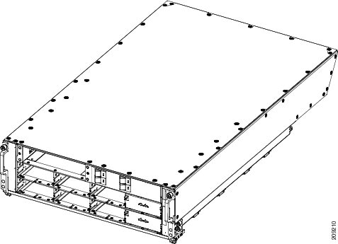
This figure shows the rear view of the modular configuration DC power shelf.
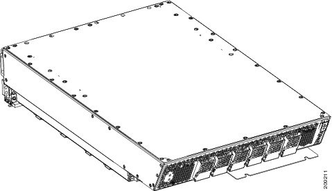
This figure shows the front view of the modular configuration AC power shelf.
This figure shows the rear view of the modular configuration AC power shelf.
Prerequisites
Remove the upper grilles on the front and rear of the chassis, if installed. Verify that the power shelf that you are about to install is the correct power shelf.
Note | Do not install the power shelf in the chassis with AC or DC PMs, or alarm module installed in the power shelf. |
Required Tools and Equipment
You need the following tools to perform this task:
- 6-in. long number 1 Phillips screwdriver
- 10-mm 6 pt. combination wrench
-
Modular configuration AC or DC power shelf
- AC power shelf (Cisco product number CRS-FCC-PSH-AC=)
- DC power shelf (Cisco product number CRS-FCC-PSH-DC=)
Steps
To install the modular configuration power shelf, perform the following steps:
1. Using the 10-mm wrench, loosen the two bolts on the rear of the chassis that clamp the rear of the power shelf to the chassis, as shown in this figure.
2. Install the mounting blocks on the left and right sides of the chassis. The left side is shown in this figure. A second mounting block is located on the right side.
3. Unscrew the ejector handles from the front face of the shelf, one on each side.
4. Holding the power shelf underneath with one hand and steadying it with the other, lift the shelf up and slide it partway into the power shelf slot on the front (SFC) side of the chassis.
5. Grasping both handles simultaneously, push both the left and right handles up in unison to push the shelf into the chassis. See the figure Using Handles to Push the Shelf into the Chassis. Slide the shelf all the way into the chassis, pushing in the shelf until both handles hook around the pins, as shown in the figure Shelf Handles Hooked Around Pins.
6. Use the wrench to tighten the two bolts that attach the rear of the power shelf to the rear of the chassis.
7. Using the screwdriver, turn the captive screws at the top of the left and right handles, as shown in the figure below.
8. Use the screwdriver to screw the shelf to the left and right mounting blocks through the handle holes. There are four holes, two on each handle, as shown in the figure.
DETAILED STEPS
| Step 1 | Using the 10-mm
wrench, loosen the two bolts on the rear of the chassis that clamp the rear of
the power shelf to the chassis, as shown in this figure.
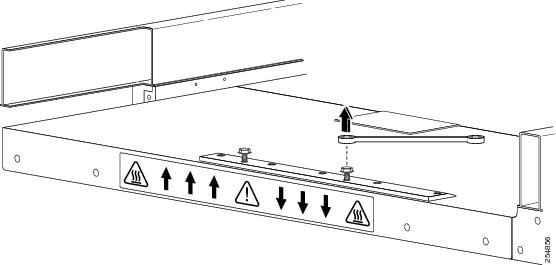 | ||||||||
| Step 2 | Install the
mounting blocks on the left and right sides of the chassis. The left side is
shown in this figure. A second mounting block is located on the right side.
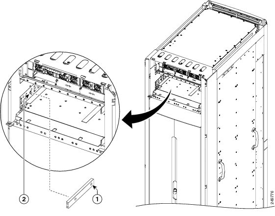
| ||||||||
| Step 3 | Unscrew the
ejector handles from the front face of the shelf, one on each side.
| ||||||||
| Step 4 | Holding the
power shelf underneath with one hand and steadying it with the other, lift the
shelf up and slide it partway into the power shelf slot on the front (SFC) side
of the chassis.
| ||||||||
| Step 5 | Grasping both
handles simultaneously, push both the left and right handles up in unison to
push the shelf into the chassis. See the figure
Using Handles to Push the Shelf into the Chassis. Slide
the shelf all the way into the chassis, pushing in the shelf until both handles
hook around the pins, as shown in the figure
Shelf Handles Hooked Around Pins.
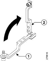
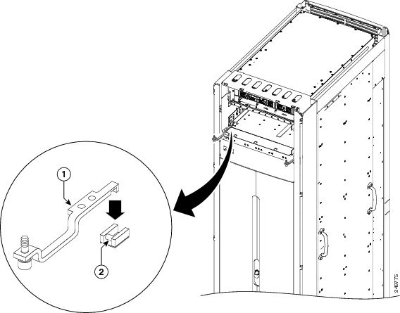
| ||||||||
| Step 6 | Use the wrench to tighten the two bolts that attach the rear of the power shelf to the rear of the chassis. | ||||||||
| Step 7 | Using the screwdriver, turn the captive screws at the top of the left and right handles, as shown in the figure below. | ||||||||
| Step 8 | Use the
screwdriver to screw the shelf to the left and right mounting blocks through
the handle holes. There are four holes, two on each handle, as shown in the
figure.
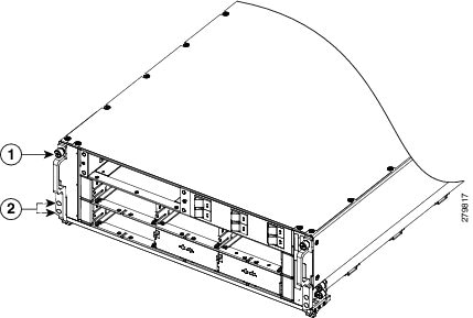
|
What to Do Next
After the modular configuration power shelves are installed in the chassis, install the grounding lug and brackets, and AC or DC power shelf wiring. Continue to the c_Installing_Power_Shelf_Grounding_Brackets_1273947.xml and the c_Installing_AC_or_DC_Power_Self_Wiring_1132672.xml for instructions.
Removing a Modular Configuration Power Shelf
This section describes how to remove an AC or DC modular configuration power shelf from the FCC.
Prerequisites
Before performing this task, remove the upper grilles on the front (SFC) side and rear (OIM) side of the chassis, AC or DC PMs, alarm module, AC or DC input wiring from the shelf you want to disconnect, and power shelf grounding brackets. For more information, see the c_Removing_a_Modular_Configuration_Power_Module_1211341.xml, the c_Removing_a_Modular_Configuration_Alarm_Module_1257452.xml, and the c_Removing_Power_Shelf_Grounding_Brackets_1200963.xml.
Required Tools and Equipment
You need the following tools to perform this task:
- 6 in. long number 1 Phillips screwdriver
- 10-mm 6 pt. combination wrench
Caution | Do not use the handles for lifting or supporting the power shelf, since this could severely damage the handles. |
Caution | Do not bend the handles sideways during any part of the removal process. |
Steps
To remove a modular configuration power shelf, perform the following steps:
1. Using the wrench, loosen the two bolts on the rear of the chassis that clamp the rear of the power shelf to the rear of the chassis. See this figure.
2. Insert the screwdriver through the hole in the mounting handles, and unscrew the shelf from the right and left side of the mounting blocks. See this figure.
3. Using the screwdriver, unscrew the captive screw on the left and right handles. There are two captive screws, one on each handle, as shown in the above figure.
4. Grasping both handles simultaneously, pull both the left and right handles down in unison to pull the shelf partially out of the chassis.
5. When the shelf is partially out of the chassis and the ejector handles are away from the pins, hand-tighten the handle screws back into the shelf.
6. Slide out the shelf out so that two people can safely remove it and carefully set it down on a flat surface.
DETAILED STEPS
| Step 1 | Using the
wrench, loosen the two bolts on the rear of the chassis that clamp the rear of
the power shelf to the rear of the chassis. See this figure.
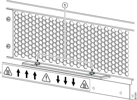
| ||||||
| Step 2 | Insert the
screwdriver through the hole in the mounting handles, and unscrew the shelf
from the right and left side of the mounting blocks. See this figure.
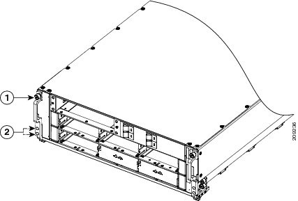
| ||||||
| Step 3 | Using the
screwdriver, unscrew the captive screw on the left and right handles. There are
two captive screws, one on each handle, as shown in the above figure.
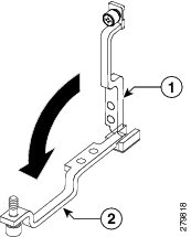
| ||||||
| Step 4 | Grasping both handles simultaneously, pull both the left and right handles down in unison to pull the shelf partially out of the chassis. | ||||||
| Step 5 | When the shelf is partially out of the chassis and the ejector handles are away from the pins, hand-tighten the handle screws back into the shelf. | ||||||
| Step 6 | Slide out the
shelf out so that two people can safely remove it and carefully set it down on
a flat surface.
|
What to Do Next
After performing this task, replace any front (SFC) side cosmetic covers.
Installing Power Shelf Grounding Brackets
This section describes how to install the external grounding brackets on the FCC modular configuration power shelf. The installation procedure for installing the power shelf grounding brackets is the same for both the AC and DC modular configuration power shelves.
Caution | Verify that the chassis is connected to a reliable earth ground; the ground cable must be installed in accordance with local electrical safety standards. For more information, see c_Bonding_and_Grounding_Guidelines_1165801. |
Prerequisites
Before performing this task, ensure that the chassis grounding cable and both power shelves are installed in the chassis. See the c_Installing_the_Chassis_Ground_cable_1298430.xml and the c_Installing_a_Modular_Configuration_Power_Shelf_1249350.xml for more information. Remove the upper grille on the rear (OIM) side of the chassis, if installed.
Required Tools and Equipment
You need the following tools to perform this task:
- ESD-preventive wrist strap
- 3/8-in. ratchet wrench with 10-mm socket
- Torque wrench with 10-mm socket and rated accuracy at 20 in.-lb (2.26 N-m)
Steps
To install the power shelf grounding brackets, go to the rear (OIM) side of the chassis and perform the following steps:
1. Attach the ESD-preventive wrist strap to your wrist and connect its leash to one of the ESD connection sockets on the rear (OIM) side of the chassis or a bare metal surface on the chassis.
2. Align the shelf grounding bracket with the power shelves.
3. Attach the shelf grounding bracket to both power shelves using the four M6 hex head bolts provided. Do not tighten. See this figure.
4. Attach the grounding L-bracket to the shelf grounding bracket using the two M6 hex nuts provided. Do not tighten. See this figure.
5. Attach the grounding L-bracket to the chassis using the two M6 hex bolts provided. Use the torque wrench to tighten the M6 hex bolts to a torque of 20 in-lb (2.26 N-m).
6. Using the torque wrench, tighten the four M6 hex bolts attaching the grounding bracket to the power shelves to a torque of 20 in-lb (2.26 N-m).
7. Using the torque wrench, tighten the two M6 hex nuts attaching the L-bracket to the Power shelf to a torque of 20 in-lb (2.26 N-m).
DETAILED STEPS
| Step 1 | Attach the ESD-preventive wrist strap to your wrist and connect its leash to one of the ESD connection sockets on the rear (OIM) side of the chassis or a bare metal surface on the chassis. | ||||||||||||||||
| Step 2 | Align the shelf grounding bracket with the power shelves. | ||||||||||||||||
| Step 3 | Attach the shelf grounding bracket to both power shelves using the four M6 hex head bolts provided. Do not tighten. See this figure. | ||||||||||||||||
| Step 4 | Attach the
grounding L-bracket to the shelf grounding bracket using the two M6 hex nuts
provided. Do not tighten. See this figure.
| ||||||||||||||||
| Step 5 | Attach the grounding L-bracket to the chassis using the two M6 hex bolts provided. Use the torque wrench to tighten the M6 hex bolts to a torque of 20 in-lb (2.26 N-m). | ||||||||||||||||
| Step 6 | Using the torque wrench, tighten the four M6 hex bolts attaching the grounding bracket to the power shelves to a torque of 20 in-lb (2.26 N-m). | ||||||||||||||||
| Step 7 | Using the torque wrench, tighten the two M6 hex nuts attaching the L-bracket to the Power shelf to a torque of 20 in-lb (2.26 N-m). |
What to Do Next
After the power shelf grounding brackets have been installed in the chassis, install the input wiring for the power shelf (see c_Installing_AC_or_DC_Power_Self_Wiring_1132672.xml),install the alarm module (see c_Installing_a_Modular_Configuration_Alarm_Module_1257400.xml), and install the PMs (see c_Installing_a_Modular_Configuration_Power_Module_1211302.xml).
Removing Power Shelf Grounding Brackets
This section describes how to remove the power shelf grounding brackets for the Cisco CRS Fabric Card Chassis modular configuration power system. The procedure for removing the power shelf grounding brackets is the same for both the AC and DC modular configuration power supplies.
Prerequisites
Before performing this task, power down and remove any PMs and the alarm module in the shelf you want to remove, and remove the power wiring. See the c_Removing_a_Modular_Configuration_Power_Module_1211341.xml, thec_Removing_a_Modular_Configuration_Alarm_Module_1257452.xml, and the c_Installing_Modular_Configuration_AC_Power_Shelf_Wiring_1274070.xml for more information. Remove the upper grille on the rear (OIM) side of the chassis, if installed.
Required Tools and Equipment
You need the following tools to perform this task:
- ESD-preventive wrist strap
- 3/8-in. ratchet wrench with 10-mm socket
Steps
To remove the power shelf grounding brackets, go to the rear (OIM) side of the chassis and perform the following steps:
1. Attach the ESD-preventive wrist strap to your wrist and connect its leash to one of the ESD connection sockets on the rear (OIM) side of the chassis or a bare metal surface on the chassis.
2. Using a 10 mm socket wrench, loosen the two M6 hex nuts that attach the L-bracket to the power shelf. Do not fully remove. See this figure.
3. Using a 10 mm socket wrench, loosen the four M6 hex bolts that attach the grounding bracket to the power shelves. Do not fully remove. See above figure.
4. Use a 10 mm socket wrench to remove the M6 hex bolts that attach the grounding L-bracket to the chassis. See above figure.
5. Remove the two M6 hex nuts that attach the grounding L-bracket to the shelf grounding bracket.
6. Remove the grounding L-bracket. See above figure.
7. Remove the four M6 hex bolts that attach the grounding bracket to the power shelves.
8. Remove the shelf grounding bracket from the power shelves. See above figure.
9. If the chassis is being replaced, use the 10-mm socket wrench to remove the ground cable from the grounding point on top of the chassis rear (OIM) side panel.
DETAILED STEPS
| Step 1 | Attach the ESD-preventive wrist strap to your wrist and connect its leash to one of the ESD connection sockets on the rear (OIM) side of the chassis or a bare metal surface on the chassis. | ||||||||||||||||||
| Step 2 | Using a 10 mm
socket wrench, loosen the two M6 hex nuts that attach the L-bracket to the
power shelf. Do not fully remove. See this figure.
| ||||||||||||||||||
| Step 3 | Using a 10 mm socket wrench, loosen the four M6 hex bolts that attach the grounding bracket to the power shelves. Do not fully remove. See above figure. | ||||||||||||||||||
| Step 4 | Use a 10 mm socket wrench to remove the M6 hex bolts that attach the grounding L-bracket to the chassis. See above figure. | ||||||||||||||||||
| Step 5 | Remove the two M6 hex nuts that attach the grounding L-bracket to the shelf grounding bracket. | ||||||||||||||||||
| Step 6 | Remove the grounding L-bracket. See above figure. | ||||||||||||||||||
| Step 7 | Remove the four M6 hex bolts that attach the grounding bracket to the power shelves. | ||||||||||||||||||
| Step 8 | Remove the shelf grounding bracket from the power shelves. See above figure. | ||||||||||||||||||
| Step 9 | If the chassis
is being replaced, use the 10-mm socket wrench to remove the ground cable from
the grounding point on top of the chassis rear (OIM) side panel.
|
What to Do Next
After the power shelf grounding brackets have been removed, the power shelf can be removed from the chassis. See c_Removing_a_Modular_Configuration_Power_Shelf_1199821.xml.
Installing AC or DC Power Self Wiring
This section describes how to connect the DC input wiring to the rear of the power shelf and install the DC terminal block covers and AC cords on the FCC.
- Installing Modular Configuration DC Power Shelf Wiring
- Prerequisites
- Required Tools and Equipment
- Steps
- Installing DC Terminal Block Covers
- Required Tools and Equipment
- Steps
- Installing Modular Configuration AC Power Shelf Wiring
- Prerequisites
- Required Tools and Equipment
- Steps
- What to do next
Installing Modular Configuration DC Power Shelf Wiring
This section describes how to install the DC input wiring on the modular configuration DC power shelf.
Note | When wiring the power shelf, be sure to connect the chassis ground cable and install auxiliary grounding brackets first. For more information, see the c_Bonding_and_Grounding_Guidelines_1165801.xml and the c_Installing_Power_Shelf_Grounding_Brackets_1273947.xml. |
Note | Do not connect the ground cables directly to the power shelf. For more information, see the c_Installing_Power_Shelf_Grounding_Brackets_1273947.xml. |
This figure shows the cable wiring for the modular configuration DC power shelf.
For additional power shelf details, see Cisco CRS Series Carrier Routing System Description or Appendix 1, Cisco CRS-1 Carrier Routing System Fabric Card Chassis Specifications.
Prerequisites
Before performing this task, ensure that both power shelves are installed in the chassis. Remove the upper grille on the rear (OIM) side of the chassis, if installed.
Caution | Before installing wiring on the power shelf, make sure that the input power cables are not energized. |
Required Tools and Equipment
You need the following tools to perform this task:
- ESD-preventive wrist strap
- Crimping tool and lug specific die
- 3/8 in. ratchet wrench with 10-mm socket
- Torque wrench with 10-mm 6-pt. socket and rated accuracy at 20 in.-lb (2.26 N-m)
Steps
To wire the modular configuration DC power shelf, perform the following steps:
1. Attach the ESD-preventive wrist strap to your wrist and connect its leash to one of the ESD connection sockets on the front (SFC) side of the chassis or a bare metal surface on the chassis.
2. Remove the terminal block covers.
3. Verify the following resistance values:
4. Use the crimping tool mandated by the lug manufacturer to crimp the lugs to the DC-input cables. For details on lugs, see the c_DC_Power_Systems_1062204.xml.
5. Using the 10-mm 6 pt. socket wrench, attach the positive and negative cable pairs to each terminal block for both power shelves. Use the torque wrench to tighten to a torque of 20 in.-lb (2.26 N-m).
6. Reattach the terminal covers. For more information, see the c_Installing_DC_Terminal_Block_Covers_1255695.xml.
DETAILED STEPS
| Step 1 | Attach the ESD-preventive wrist strap to your wrist and connect its leash to one of the ESD connection sockets on the front (SFC) side of the chassis or a bare metal surface on the chassis. | ||
| Step 2 | Remove the terminal block covers. | ||
| Step 3 | Verify the
following resistance values:
| ||
| Step 4 | Use the
crimping tool mandated by the lug manufacturer to crimp the lugs to the
DC-input cables. For details on lugs, see the
c_DC_Power_Systems_1062204.xml.
The cable should be sized according to local and national installation requirements. Use only copper cable.
| ||
| Step 5 | Using the 10-mm 6 pt. socket wrench, attach the positive and negative cable pairs to each terminal block for both power shelves. Use the torque wrench to tighten to a torque of 20 in.-lb (2.26 N-m). | ||
| Step 6 | Reattach the terminal covers. For more information, see the c_Installing_DC_Terminal_Block_Covers_1255695.xml. |
Installing DC Terminal Block Covers
This figure shows the terminal block cover.
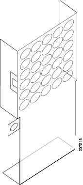
Note | Install the terminal block cover after the input wiring is installed, but before the power is energized. |
Required Tools and Equipment
You need the following to perform this task:
- ESD-preventive wrist strap
- 6-in. long number 1 Phillips screwdriver
Steps
To install the DC terminal block covers, go to the rear (OIM) side of the chassis and perform the following steps:
1. Attach the ESD-preventive wrist strap to your wrist and connect its leash to one of the ESD connection sockets on the front (SFC) side of the chassis or a bare metal surface on the chassis.
2. Align the DC terminal block cover with the cover latch tab.
3. Use the screwdriver to secure the screw into the mounting standoff, as shown in this figure.
DETAILED STEPS
| Step 1 | Attach the ESD-preventive wrist strap to your wrist and connect its leash to one of the ESD connection sockets on the front (SFC) side of the chassis or a bare metal surface on the chassis. | ||||||||||||||||
| Step 2 | Align the DC terminal block cover with the cover latch tab. | ||||||||||||||||
| Step 3 | Use the
screwdriver to secure the screw into the mounting standoff, as shown in this
figure.
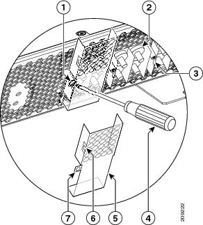
|
Installing Modular Configuration AC Power Shelf Wiring
This section describes how to install input AC cords on the rear of the modular configuration power shelf.
Note | When wiring the power shelf, be sure to connect the chassis ground cable and install auxiliary grounding brackets first. For more information, see the c_Bonding_and_Grounding_Guidelines_1165801.xml and the c_Installing_Power_Shelf_Grounding_Brackets_1273947.xml . |
Do not connect the ground cables directly to the modular configuration power shelf. For more information, see the c_Installing_Power_Shelf_Grounding_Brackets_1273947.xml .
Prerequisites
Before performing this task, ensure that both power shelves are installed in the chassis. Remove the upper grille on the rear (OIM) side of the chassis, if installed.
If you have AC Delta or AC Wye at your equipment, ensure that two Cisco CRS PDUs are installed to convert 3-phase AC input power to single-phase AC input power for the power shelves. For further information, refer to Cisco CRS 3-Phase AC Power Distribution Unit Installation Guide .
Note | Before installing input AC cords on the power shelf, make sure that the input power cords are not energized. |
Required Tools and Equipment
You need the following tools to perform this task:
- 6 in. long number 1 Phillips screwdriver
Steps
To install the AC cords, go to the rear of the chassis and perform the following steps:
1. Insert the cords into the cord clamps, see this figure.
2. Use the screwdriver to tighten the screws that clamp the cords in place, see the above figure.
DETAILED STEPS
| Step 1 | Insert the
cords into the cord clamps, see this figure.
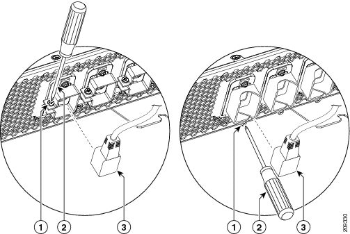
| ||||||||||||
| Step 2 | Use the screwdriver to tighten the screws that clamp the cords in place, see the above figure. |
What to do next
After you install the DC terminal block covers or AC cords, install the alarm module (see c_Installing_a_Modular_Configuration_Alarm_Module_1257400.xml).
Removing AC or DC Power Shelf Wiring
This section describes how to remove the DC input wiring, DC terminal blocks and AC cords from the rear of the power shelf on the FCC.
- Removing Modular Configuration DC Power Shelf Wiring
- Prerequisites
- Required Tools and Equipment
- Steps
- Removing Modular Configuration AC Power Shelf Wiring
- Prerequisites
- Required Tools and Equipment
- Steps
- What to do next
Removing Modular Configuration DC Power Shelf Wiring
This section describes how to remove the DC power shelf wiring from the rear of the modular configuration DC power shelf.
For additional power shelf details, see Cisco CRS Series Carrier Routing System Description or Appendix 1, “Cisco CRS-1 Carrier Routing System Fabric Card Chassis Specifications.”
Prerequisites
Before performing this task power down and remove DC PMs and the alarm module in the shelf you want to disconnect. Remove the upper grille on the rear (OIM) side of the chassis, if installed.
Note | Before removing wiring from the power shelf, make sure that the input power cables are not energized. |
Required Tools and Equipment
You need the following tools to perform this task:
- ESD-preventive wrist strap
- 6 in. long number 1 Phillips screwdriver
- 3/8-in. ratchet wrench with 10-mm socket
Steps
To disconnect wiring from the fixed configuration DC power shelf, perform the following steps:
1. Attach the ESD-preventive wrist strap to your wrist and connect its leash to one of the ESD connection sockets on the front (SFC) side of the chassis or a bare metal surface on the chassis.
2. Use the screwdriver to remove the screw that secures the terminal block cover into the mounting standoff.
3. Remove the terminal block cover.
4. Using the 10-mm socket wrench, remove the positive and negative cable pairs from each terminal block.
5. Replace the terminal block cover.
DETAILED STEPS
| Step 1 | Attach the ESD-preventive wrist strap to your wrist and connect its leash to one of the ESD connection sockets on the front (SFC) side of the chassis or a bare metal surface on the chassis. | ||||||||||||||||
| Step 2 | Use the
screwdriver to remove the screw that secures the terminal block cover into the
mounting standoff.
| ||||||||||||||||
| Step 3 | Remove the terminal block cover. | ||||||||||||||||
| Step 4 | Using the 10-mm
socket wrench, remove the positive and negative cable pairs from each terminal
block.
| ||||||||||||||||
| Step 5 | Replace the terminal block cover. |
Removing Modular Configuration AC Power Shelf Wiring
This section describes how to remove input AC cords from the rear of the modular configuration AC power shelf.
Prerequisites
Before performing this task power down and remove AC PMs and the alarm module in the shelf you want to disconnect. Remove the upper grille on the rear (OIM) side of the chassis, if installed.
Note | Before removing wiring from the power shelf, make sure that the input power cables are not energized. |
Required Tools and Equipment
You need the following tools to perform this task:
- 6 in. long number 1 Phillips screwdriver
Steps
To remove the AC cords, go to the rear of the chassis and perform the following steps:
1. Use the screwdriver to loosen the screws that clamp the cords in place, see this figure .
2. Remove the cords from the cord clamps.
DETAILED STEPS
| Step 1 | Use the
screwdriver to loosen the screws that clamp the cords in place, see this figure
.
| ||||||||||
| Step 2 | Remove the cords from the cord clamps. |
What to do next
After you remove the DC wiring and DC terminal block covers or AC cords, remove the power shelf. See the c_Removing_a_Modular_Configuration_Power_Shelf_1199821.xml .
Installing a Modular Configuration Alarm Module
This section describes how to install the alarm module, shown in this figure, in a modular configuration AC or DC power shelf in the FCC.
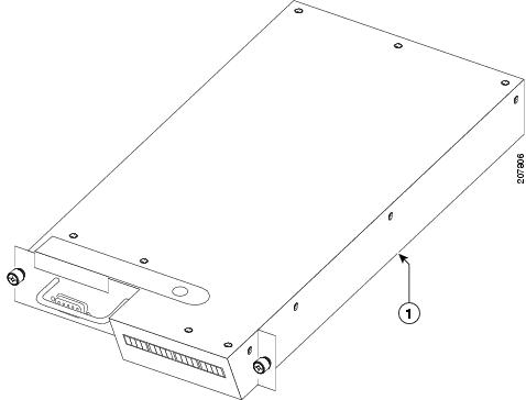
|
1 |
Side of alarm module to be installed on right side of opening. |
Caution | Do not attempt to install the alarm module until the modular configuration power shelf is in place and screwed into the chassis. |
Prerequisites
Before performing this task remove the upper grille on the front (SFC) side of the chassis, if installed.
Required Tools and Equipment
You need the following tools to perform this task:
- ESD-preventive wrist strap
- 6-in. long number 1 Phillips screwdriver
- Modular configuration alarm module (Cisco product number CRS-16-ALARM-C=)
Steps
To install the alarm module, perform the following steps:
1. Attach the ESD-preventive wrist strap to your wrist and connect its leash to one of the ESD connection sockets on the front (SFC) side of the chassis or a bare metal surface on the chassis.
2. Slide the alarm module into the top left bay on the power shelf, with the display on the right side and the handle on the left side.
3. Hand tighten the two captive screws on the alarm module.
4. Use the screwdriver to securely fasten the alarm module to the power shelf.
DETAILED STEPS
| Step 1 | Attach the ESD-preventive wrist strap to your wrist and connect its leash to one of the ESD connection sockets on the front (SFC) side of the chassis or a bare metal surface on the chassis. |
| Step 2 | Slide the alarm module into the top left bay on the power shelf, with the display on the right side and the handle on the left side. |
| Step 3 | Hand tighten the two captive screws on the alarm module. |
| Step 4 | Use the screwdriver to securely fasten the alarm module to the power shelf. |
What to Do Next
After the alarm module is installed in the power shelf, you can install the PMs. Continue to the c_Installing_a_Modular_Configuration_Power_Module_1211302.xml for instructions.
Removing a Modular Configuration Alarm Module
This section describes how to remove the alarm module from the modular configuration power shelf installed in the FCC.
Prerequisites
Before performing this task remove the upper grille on the front (SFC) side of the chassis, if installed.
Required Tools and Equipment
You need the following tools to perform this task:
- ESD-preventive wrist strap
- 6-in. long number 1 Phillips screwdriver
Steps
To remove the alarm module from a modular configuration power shelf, perform the following steps:
1. Attach the ESD-preventive wrist strap to your wrist and connect its leash to one of the ESD connection sockets on the front (SFC) side of the chassis or a bare metal surface on the chassis.
2. Remove the upper grille on the front (SFC) side of the chassis. For detailed instructions, see Installing and Removing Exterior Cosmetic Components” chapter.
3. Use the screwdriver to loosen the two captive screws securing the alarm module to the power shelf.
4. Loosen by hand the panel fasteners on the alarm module.
5. Carefully slide the alarm module out of the power shelf.
DETAILED STEPS
| Step 1 | Attach the ESD-preventive wrist strap to your wrist and connect its leash to one of the ESD connection sockets on the front (SFC) side of the chassis or a bare metal surface on the chassis. |
| Step 2 | Remove the upper grille on the front (SFC) side of the chassis. For detailed instructions, see Installing and Removing Exterior Cosmetic Components” chapter. |
| Step 3 | Use the screwdriver to loosen the two captive screws securing the alarm module to the power shelf. |
| Step 4 | Loosen by hand the panel fasteners on the alarm module. |
| Step 5 | Carefully slide the alarm module out of the power shelf. |
What to Do Next
After the modular configuration alarm module is removed from the power shelf, you can remove the power shelf wiring. Continue to the c_Removing_AC_or_DC_Power_Shelf_Wiring_1274703.xml for instructions
Installing a Modular Configuration Power Module
This section describes how to install the AC or DC PMs, shown in this figure, in a modular configuration power shelf installed in the FCC.
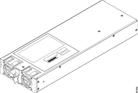
Caution | Do not attempt to install the PM until the modular configuration power shelf is in place and screwed into the chassis. |
Prerequisites
Before performing this task remove the upper grille on the front (SFC) side of the chassis, if installed.
Required Tools and Equipment
You need the following tools to perform this task:
- ESD-preventive wrist strap
- 6-in. long number 1 Phillips screwdriver
- Torque screwdriver with number 1 Phillips bit and rated accuracy at 5.5 in.-lb (0.62 N-m)
-
Modular Configuration PM
- AC PM (Cisco product number CRS-PM-AC=), or
- DC PM (Cisco product number CRS-PM-DC=)
Steps
To install the PM in a modular configuration power shelf, perform the following steps:
1. Attach the ESD-preventive wrist strap to your wrist and connect its leash to one of the ESD connection sockets on the front (SFC) side of the chassis or a bare metal surface on the chassis.
2. Using two hands to support and guide the PM, slide it into the power shelf.
3. Flip up the ejector and with nominal install torque of 5.5 in-lb (0.62 N m) of torque, screw the PM into the shelf (see this figure). Do not exceed an install torque value of 10 in-lb (1.13 N-m).
4. Fill the power shelf to the required configuration
DETAILED STEPS
| Step 1 | Attach the ESD-preventive wrist strap to your wrist and connect its leash to one of the ESD connection sockets on the front (SFC) side of the chassis or a bare metal surface on the chassis. | ||
| Step 2 | Using two hands to support and guide the PM, slide it into the power shelf. | ||
| Step 3 | Flip up the
ejector and with nominal install torque of 5.5 in-lb (0.62 N m) of torque,
screw the PM into the shelf (see this figure). Do not exceed an install torque
value of 10 in-lb (1.13 N-m).
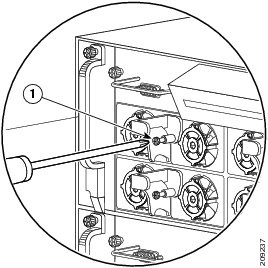
| ||
| Step 4 | Fill the power shelf to the required configuration |
What to Do Next
After the modular configuration PMs are installed in the chassis, install power module slot covers in empty PM slots, if any. For more information, see the c_Installing_a_Modular_Configuration_Power_Module_Slot_Cover_1373536.xml.
Removing a Modular Configuration Power Module
This section describes how to remove a PM, as shown in Figure 1, from a modular configuration power shelf in the FCC.
Prerequisites
Before performing this task remove the upper grille on the front (SFC) side of the chassis, if installed.
Required Tools and Equipment
You need the following tools to perform this task:
- ESD-preventive wrist strap
- 6-in. long number 1 Phillips screwdriver
Steps
To remove a PM from a modular configuration power shelf, perform the following steps:
1. Attach the ESD-preventive wrist strap to your wrist and connect its leash to one of the ESD connection sockets on the front (SFC) side of the chassis or a bare metal surface on the chassis.
2. Remove the upper grille on the front (SFC) side of the chassis. For detailed instructions, go to Installing and Removing Exterior Cosmetic Components chapter.
3. Using the screwdriver, unscrew the ejector from the PM.
4. Flip down the ejector, slide the power module out of the power shelf, and place it carefully down on a flat surface.
DETAILED STEPS
| Step 1 | Attach the ESD-preventive wrist strap to your wrist and connect its leash to one of the ESD connection sockets on the front (SFC) side of the chassis or a bare metal surface on the chassis. |
| Step 2 | Remove the upper grille on the front (SFC) side of the chassis. For detailed instructions, go to Installing and Removing Exterior Cosmetic Components chapter. |
| Step 3 | Using the screwdriver, unscrew the ejector from the PM. |
| Step 4 | Flip down the ejector, slide the power module out of the power shelf, and place it carefully down on a flat surface. |
What to Do Next
After the alarm module and PMs have been removed from the chassis, you can remove the power shelf. Continue to the c_Removing_a_Modular_Configuration_Power_Shelf_1199821.xml for instructions.
Installing a Modular Configuration Power Module Slot Cover
This section describes how to install power module slot covers, in empty power module slots in the power shelves installed in the FCC. For complete information on regulatory compliance and safety, see Regulatory Compliance and Safety Information for the Cisco CRS Carrier Routing System.
Although the AC and DC power module slot covers differ slightly in size, they are installed using the same procedures.
Prerequisites
Before performing this task, you must first remove the upper grille on the front (SFC) side of the chassis, if installed, and install the alarm module and power modules to the required configuration in each power shelf.
Required Tools and Equipment
You need the following tools to perform this task:
- ESD-preventive wrist strap
-
AC or DC PM Slot Cover
- AC PM slot cover (Cisco product number 700–29097–xx), or
- DC PM slot cover (Cisco product number 700–29098–xx)
Steps
To install a PM slot cover in a modular configuration power shelf, perform the following steps:
1. Attach the ESD-preventive wrist strap to your wrist and connect its leash to one of the ESD connection sockets on the front (SFC) side of the chassis or a bare metal surface on the chassis.
2. Align the PM slot cover with the empty PM slot in the power shelf.
3. Insert the two tabs on the right side of the PM slot cover into the two holes on the right side of the PM slot. See this figure.
4. Push the left side of the PM slot cover gently until it clicks into place. See this figure.
DETAILED STEPS
| Step 1 | Attach the ESD-preventive wrist strap to your wrist and connect its leash to one of the ESD connection sockets on the front (SFC) side of the chassis or a bare metal surface on the chassis. |
| Step 2 | Align the PM slot cover with the empty PM slot in the power shelf. |
| Step 3 | Insert the two tabs on the right side of the PM slot cover into the two holes on the right side of the PM slot. See this figure. |
| Step 4 | Push the left
side of the PM slot cover gently until it clicks into place. See this figure.
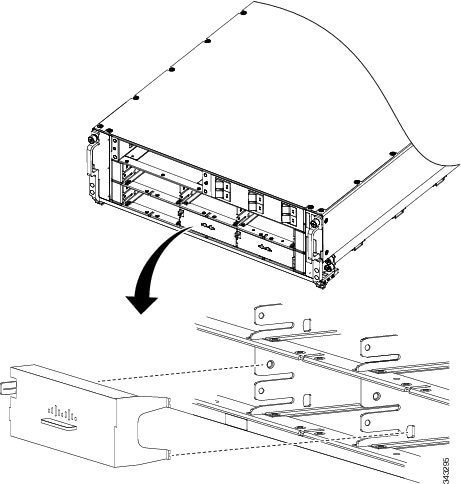 |
What to Do Next
After the PM slot covers are installed in the chassis, install the upper grille on the front (SFC) side of the chassis.
Removing a Modular Configuration Power Module Slot Cover
This section describes how to remove a PM slot cover from a PM slot in a modular configuration AC or DC power shelf. For complete information on regulatory compliance and safety, see Regulatory Compliance and Safety Information for the Cisco CRS Carrier Routing System .
Prerequisites
Before performing this task, you must first remove the upper grille on the front (SFC) side of the chassis, if installed.
Required Tools and Equipment
You need the following tools to perform this task:
- ESD-preventive wrist strap
Steps
To remove a PM slot cover from a power shelf, perform the following steps:
1. Attach the ESD-preventive wrist strap to your wrist and connect its leash to one of the ESD connection sockets on the front (SFC) side of the chassis or a bare metal surface on the chassis.
2. Gently pinch the tab on the left side of the PM slot cover to detach the PM slot cover from the PM slot. See Figure 1.
3. Remove the two tabs on the right side of the PM slot cover from the two holes on the right side of the PM slot. See Figure 1.
4. Set the PM slot cover aside.
DETAILED STEPS
| Step 1 | Attach the ESD-preventive wrist strap to your wrist and connect its leash to one of the ESD connection sockets on the front (SFC) side of the chassis or a bare metal surface on the chassis. |
| Step 2 | Gently pinch the tab on the left side of the PM slot cover to detach the PM slot cover from the PM slot. See Figure 1. |
| Step 3 | Remove the two tabs on the right side of the PM slot cover from the two holes on the right side of the PM slot. See Figure 1. |
| Step 4 | Set the PM slot cover aside. |
What to Do Next
After performing this task, install an AC or DC PM, if necessary (see the c_Installing_a_Modular_Configuration_Power_Module_1211302.xml) and re-install the upper grille on the front (SFC) side of the chassis. If you plan to remove the power shelf completely, you must first remove all of the PM slot covers, PMs, and the alarm module from the power shelf. See the c_Removing_a_Modular_Configuration_Power_Module_1211341.xml and the c_Removing_a_Modular_Configuration_Alarm_Module_1257452.xml for more information.
Power Up and Power Down a Chassis with Modular Configuration Power
This section describes how to power up and power down a chassis with a modular configuration AC or DC power shelf. For details on the chassis power system, see the c_Basic_Chassis_Power_Details_1165790.xml, the c_AC_Power_Systems_1311127.xml, and the c_DC_Power_Systems_1062204.xml. For complete information on regulatory compliance and safety, see Regulatory Compliance and Safety Information for the Cisco CRS Carrier Routing System .
Most components on the chassis, such as the PMs, alarm modules, and fan trays, can be removed or installed in the chassis while it is running. Although it is possible to install or remove a power shelf while the chassis is running, it is recommended to remove power from the chassis completely, if possible, for service protection and safety.
This figure shows the Front (SFC) side of the FCC with modular configuration power installed.
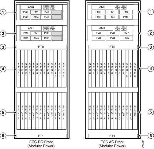
|
1 |
Power shelf, Power A |
4 |
Upper card cage |
|
2 |
Power shelf, Power B |
5 |
Lower card cage |
|
3 |
Fan tray FT0 |
6 |
Fan tray FT1 |
- Power Up a Chassis with Modular Configuration Power
- Prerequisites
- Required Tools and Equipment
- Steps
- Power Down a Chassis with Modular Configuration Power
Power Up a Chassis with Modular Configuration Power
This section describes how to power up a chassis with a modular configuration AC or DC power shelf installed.
Prerequisites
Before performing this task, you must install and wire the power shelves, and install the PMs, alarm modules, SCGE cards, and exterior cosmetic components. See the c_Installing_a_Modular_Configuration_Power_Shelf_1249350.xml, the c_Installing_AC_or_DC_Power_Self_Wiring_1132672.xml, the Installing an SCGE Card section, and Installing and Removing Exterior Cosmetic Components chapter for more information. If you have a modular configuration DC power system installed, wiring at the BDFB or at the power plant should be complete.
Required Tools and Equipment
You need the following tools to perform this task:
- ESD-preventive wrist strap
- Multimeter
Steps
To power on the chassis, perform the following steps:
1. Make sure that the facility power breakers for the upper (Power A) and lower (Power B) power shelves are in the OFF position.
2. Make sure that I/O switches on the rear of the upper (Power A) and lower (Power B) power shelves are in the OFF position.
3. Make sure all SFCs are pulled-out and disconnected from the backplane.
4. If you have a modular configuration DC power system installed:
5. Turn the facility breakers for the upper power shelf (Power A) to the ON position. Verify that the Input_OK LED on all of the PMs installed in the upper shelf are green.
6. Turn the I/O switch at the rear of the upper power shelf (Power A) to the ON position. Verify that the Output_OK LED on all of the PMs installed in the upper shelf are green.
7. Repeat step 5 and step 6 for the lower power shelf (Power B).
8. Turn the I/O switch at the rear of both upper power shelves (Power A and Power B) to the OFF position. Verify that none of the Output_OK LEDs on the PMs installed in the shelf are green.
9. Install all SFCs in the chassis. For more information, see the Installing and Removing Fabric Cards and Card Components chapter.
10. Turn the I/O switch at the rear of both power shelves (Power A and Power B) to the ON position.
11. If you have a modular configuration DC power system installed, measure the input voltage of each DC input and compare this value to the voltage measurement noted in step 4. Verify that the equipment is still receiving the correct input voltage measured in step 4.
DETAILED STEPS
| Step 1 | Make sure that the facility power breakers for the upper (Power A) and lower (Power B) power shelves are in the OFF position. | ||
| Step 2 | Make sure that I/O switches on the rear of the upper (Power A) and lower (Power B) power shelves are in the OFF position. | ||
| Step 3 | Make sure all SFCs are pulled-out and disconnected from the backplane. | ||
| Step 4 | If you have a
modular configuration DC power system installed:
| ||
| Step 5 | Turn the facility breakers for the upper power shelf (Power A) to the ON position. Verify that the Input_OK LED on all of the PMs installed in the upper shelf are green. | ||
| Step 6 | Turn the I/O switch at the rear of the upper power shelf (Power A) to the ON position. Verify that the Output_OK LED on all of the PMs installed in the upper shelf are green. | ||
| Step 7 | Repeat step 5 and step 6 for the lower power shelf (Power B). | ||
| Step 8 | Turn the I/O switch at the rear of both upper power shelves (Power A and Power B) to the OFF position. Verify that none of the Output_OK LEDs on the PMs installed in the shelf are green. | ||
| Step 9 | Install all SFCs in the chassis. For more information, see the Installing and Removing Fabric Cards and Card Components chapter. | ||
| Step 10 | Turn the I/O
switch at the rear of both power shelves (Power A and Power B) to the ON
position.
| ||
| Step 11 | If you have a modular configuration DC power system installed, measure the input voltage of each DC input and compare this value to the voltage measurement noted in step 4. Verify that the equipment is still receiving the correct input voltage measured in step 4. |
Power Down a Chassis with Modular Configuration Power
This section describes how to power down a chassis with a modular configuration AC or DC power shelf installed.
To power down the chassis, perform the following steps:
1. Turn the I/O switches at the rear of both power shelves, Power A and Power B, to the OFF position.
2. Turn off all facility power breakers (AC or DC) for the upper power shelf (Power A). Repeat for all facility power breakers for the lower power shelf (Power B).
DETAILED STEPS
| Step 1 | Turn the I/O
switches at the rear of both power shelves, Power A and Power B, to the OFF
position.
| ||
| Step 2 | Turn off all
facility power breakers (AC or DC) for the upper power shelf (Power A). Repeat
for all facility power breakers for the lower power shelf (Power B).
|
What to Do Next
This table shows the LED status indicator lights for the AC and DC PMs in a modular configuration power system.
|
LED Name |
Color |
Function or Meaning |
|---|---|---|
|
Input_OK |
Green |
On: The input power is present and within regulation range. Blinking: The input power is present but out of regulation range. Off: The input power is not present. |
|
Output_OK |
Green |
On: The output power is on. Blinking: The PM is in a power limit or an OC condition. Off: The output power is off. |
|
Internal Fault |
Red |
On: An internal fault is detected within the PM. Off: The PM has no internal fault. |
Converting from One Modular Configuration Power System to Another
To convert an FCC with a modular configuration power system from AC to DC power, or from DC to AC power, perform the following steps:
1. Power down the chassis completely and turn the facility power breakers to the OFF position. See the c_Power_Up_and_Power_Down_a_Chassis_with_Modular_Configuration_Power_1207650.xml .
2. Remove the AC or DC PMs. See the c_Removing_a_Modular_Configuration_Power_Module_1211341.xml .
3. Remove the alarm modules. See the c_Removing_a_Modular_Configuration_Alarm_Module_1257452.xml .
4. Unplug the AC power cords or remove the DC fusing from the power source. Remove the AC or DC wiring from the rear of the power shelf. See the c_Removing_AC_or_DC_Power_Shelf_Wiring_1274703.xml.
5. Remove the power shelves. See the c_Removing_a_Modular_Configuration_Power_Shelf_1199821.xml .
6. Install the new power shelves. See the c_Installing_a_Modular_Configuration_Power_Shelf_1249350.xml .
7. Install the power shelf wiring. See the c_Installing_AC_or_DC_Power_Self_Wiring_1132672.xml .
8. Install the alarm modules. See the c_Installing_a_Modular_Configuration_Alarm_Module_1257400.xml .
9. Install the AC or DC PMs. See the c_Installing_a_Modular_Configuration_Power_Module_1211302.xml .
10. Power the chassis back up. See the c_Power_Up_and_Power_Down_a_Chassis_with_Modular_Configuration_Power_1207650.xml .
DETAILED STEPS
| Step 1 | Power down the chassis completely and turn the facility power breakers to the OFF position. See the c_Power_Up_and_Power_Down_a_Chassis_with_Modular_Configuration_Power_1207650.xml . | ||
| Step 2 | Remove the AC or DC PMs. See the c_Removing_a_Modular_Configuration_Power_Module_1211341.xml . | ||
| Step 3 | Remove the alarm modules. See the c_Removing_a_Modular_Configuration_Alarm_Module_1257452.xml . | ||
| Step 4 | Unplug the AC power cords or remove the DC fusing from the power source. Remove the AC or DC wiring from the rear of the power shelf. See the c_Removing_AC_or_DC_Power_Shelf_Wiring_1274703.xml. | ||
| Step 5 | Remove the power shelves. See the c_Removing_a_Modular_Configuration_Power_Shelf_1199821.xml . | ||
| Step 6 | Install the new power shelves. See the c_Installing_a_Modular_Configuration_Power_Shelf_1249350.xml . | ||
| Step 7 | Install the
power shelf wiring. See the
c_Installing_AC_or_DC_Power_Self_Wiring_1132672.xml
.
| ||
| Step 8 | Install the alarm modules. See the c_Installing_a_Modular_Configuration_Alarm_Module_1257400.xml . | ||
| Step 9 | Install the AC or DC PMs. See the c_Installing_a_Modular_Configuration_Power_Module_1211302.xml . | ||
| Step 10 | Power the chassis back up. See the c_Power_Up_and_Power_Down_a_Chassis_with_Modular_Configuration_Power_1207650.xml . |
What to Do Next
Note | Use only one type of modular configuration power shelf—AC or DC—and its mating AC or DC PM in a chassis at one time. |
How to Convert a Chassis from Fixed Configuration Power to Modular Configuration Power
Caution | Do not attempt to convert from fixed configuration power to modular configuration power while the FCC is powered up and running. Ensure that you have powered down the system and all power is disconnected from the system. |
This section lists the steps to be performed to convert the FCC from fixed configuration power to modular configuration power.
Prerequisites
Before performing this task, you must completely power down the system and ensure that all power is disconnected from the system. See the c_Power_Up_and_Power_Down_a_Chassis_with_Modular_Configuration_Power_1207650.xml for more information.
Steps
To convert the chassis from fixed to modular configuration power, perform the following steps:
1. Remove the alarm modules. See the c_Removing_a_Fixed_Configuration_Alarm_Module_1069715.xml.
2. Remove the AC rectifiers or DC PEMs. See the c_Removing_an_AC_Rectifier_or_DC_PEM_1069631.xml.
3. Unplug the AC power cords or remove the DC fusing from the power source. Remove the AC or DC wiring from the rear of the fixed configuration power shelf, as described in the c_Removing_Fixed_Configuration_AC_Power_Shelf_Wiring_1180533.xml and the c_Removing_Fixed_Configuration_DC_Power_Shelf_Wiring_1193337.xml.
4. For fixed configuration DC only, remove the ground cable connected to the rear of the power shelf. This ground cable will not be used when installing a modular configuration power shelf. Remove the fixed configuration power shelves, as described in Figure 1.
5. Install the modular power shelves, see c_Installing_a_Modular_Configuration_Power_Shelf_1249350.xml.
6. Install the DC wiring or AC power cords on the rear of the power shelf. See the c_Installing_AC_or_DC_Power_Self_Wiring_1132672.xml for more information.
7. Install the power modules, as described in c_Installing_a_Modular_Configuration_Power_Module_1211302.xml.
8. Install the alarm modules. See c_Installing_a_Modular_Configuration_Alarm_Module_1257400.xml.
9. Replace the DC fuses or restore AC service. Power the chassis back up. See the c_Power_Up_and_Power_Down_a_Chassis_with_Modular_Configuration_Power_1207650.xml.
DETAILED STEPS
| Step 1 | Remove the alarm modules. See the c_Removing_a_Fixed_Configuration_Alarm_Module_1069715.xml. | ||
| Step 2 | Remove the AC rectifiers or DC PEMs. See the c_Removing_an_AC_Rectifier_or_DC_PEM_1069631.xml. | ||
| Step 3 | Unplug the AC power cords or remove the DC fusing from the power source. Remove the AC or DC wiring from the rear of the fixed configuration power shelf, as described in the c_Removing_Fixed_Configuration_AC_Power_Shelf_Wiring_1180533.xml and the c_Removing_Fixed_Configuration_DC_Power_Shelf_Wiring_1193337.xml. | ||
| Step 4 | For fixed configuration DC only, remove the ground cable connected to the rear of the power shelf. This ground cable will not be used when installing a modular configuration power shelf. Remove the fixed configuration power shelves, as described in Figure 1. | ||
| Step 5 | Install the
modular power shelves, see
c_Installing_a_Modular_Configuration_Power_Shelf_1249350.xml.
| ||
| Step 6 | Install the DC wiring or AC power cords on the rear of the power shelf. See the c_Installing_AC_or_DC_Power_Self_Wiring_1132672.xml for more information. | ||
| Step 7 | Install the power modules, as described in c_Installing_a_Modular_Configuration_Power_Module_1211302.xml. | ||
| Step 8 | Install the alarm modules. See c_Installing_a_Modular_Configuration_Alarm_Module_1257400.xml. | ||
| Step 9 | Replace the DC fuses or restore AC service. Power the chassis back up. See the c_Power_Up_and_Power_Down_a_Chassis_with_Modular_Configuration_Power_1207650.xml. |
 Feedback