- Preface
- Overview
- Installing and Removing Power Components
- Installing and Removing Air Circulation Components
- Installing and Removing Fabric Cards and Card Components
- Installing and Removing Exterior Cosmetic Components
- Upgrading Chassis Components
- Cisco CRS-1 Carrier Routing System Fabric Card Chassis Specifications
- Product IDs
Cisco CRS Carrier Routing System Fabric Card Chassis Installation Guide
Bias-Free Language
The documentation set for this product strives to use bias-free language. For the purposes of this documentation set, bias-free is defined as language that does not imply discrimination based on age, disability, gender, racial identity, ethnic identity, sexual orientation, socioeconomic status, and intersectionality. Exceptions may be present in the documentation due to language that is hardcoded in the user interfaces of the product software, language used based on RFP documentation, or language that is used by a referenced third-party product. Learn more about how Cisco is using Inclusive Language.
- Updated:
- February 15, 2017
Chapter: Installing and Removing Exterior Cosmetic Components
Installing and Removing Exterior Cosmetic Components
This chapter provides instructions on how to install and remove the Cisco CRS Carrier Routing System Fabric Card Chassis exterior cosmetic components.
This chapter presents the following topics:
- Information about the Exterior Cosmetic Components
- Installing the Front (SFC) Side Cosmetic Components
- Removing the Front (SFC) Side Cosmetic Components
- Installing the Rear (OIM) Side Cosmetic Components
Information about the Exterior Cosmetic Components
This section contains general information about the exterior cosmetic components.
The FCC is shipped with exterior cosmetic components for the front (SFC) and rear (OIM) side of the chassis.
The figure below shows the exterior cosmetics for the front (SFC) side of a chassis with fixed configuration power shelves installed. The front view of an FCC with modular configuration power shelves installed is similar.
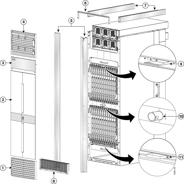
|
1 |
Lower grille |
7 |
Unistruts |
|
2 |
Doors |
8 |
Lower grille screen and frame assembly |
|
3 |
Logo bezel |
9 |
Upper door stop |
|
4 |
Upper grille (optional) |
10 |
Strike tube |
|
5 |
Vertical cable troughs |
11 |
Lower door stop |
|
6 |
Upper grille support |
|
|
The figure below shows the exterior cosmetics on the rear (OIM) side of an FCC with fixed configuration power shelves installed. The rear view of an FCC with modular configuration power shelves installed is similar.
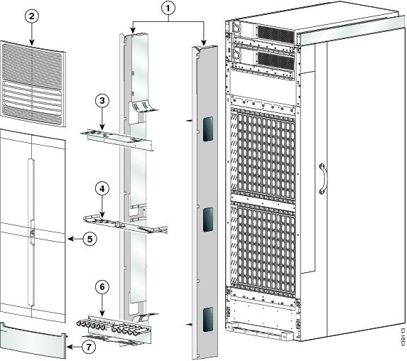
|
1 |
Vertical cable troughs |
5 |
Doors |
|
2 |
Upper grille |
6 |
Lower horizontal cable guide assembly |
|
3 |
Upper horizontal cable guide |
7 |
Lower bezel |
|
4 |
Middle horizontal cable guide with strike tube attached |
|
|
Installing the Front (SFC) Side Cosmetic Components
This section describes how to install the front (SFC) side exterior cosmetic covers on the FCC. Figure 1 shows the exterior cosmetics for the front (SFC) side of a chassis with fixed configuration power shelves installed. The front view of an FCC with modular configuration power shelves installed is similar.
 Note | While it is possible to install the various front exterior components on the chassis in a different order, it is easier to install them in the order outlined in this section. |
This section describes how to perform the following tasks:
Prerequisites
Before performing this task, you must first unpack and secure the chassis. See Cisco CRS Carrier Routing System Fabric Card Chassis Unpacking, Moving, and Securing Guide .
Required Tools and Equipment
You need the following tools and part to perform this task:
- 8-in. long number 1 Phillips screwdriver—magnetic head preferable
- 10-mm hex key wrench
- 2-mm hex key wrench (for adjusting door set screws)
- Torque wrench with 10-mm hex key and rated accuracy at 40 to 50 in-lb. (4.52 to 5.65 N-m)
- Front cosmetic kit (Cisco product number: CRS-FCC-FRNT-CM=)
- Front doors (Cisco product number: CRS-FCC-DRS-FR=)
Steps
To install the front (SFC) side exterior cosmetic components, perform the following steps:
1. Attach each unistrut to the top of the chassis by inserting the twelve M12 hex head bolts and washers, six for each strut, into the bolt holes on the inside of the strut and tightening with the 10-mm hex key wrench. The closed end of a unistrut faces the front [SFC] side of the chassis), see the figure below.
2. Attach the front upper grille support (number 1 in the figure below) to the unistruts by inserting four M4x14-mm flat head screws, two for each unistrut, through the holes at the top of the front vertical cable troughs and tightening them to the unistruts with the screwdriver.
3. Attach the power shelf shutoff extenders (number 2 in the figure below) by inserting the four M4 panhead screws, two for each power shelf shutoff extender, and tightening them with the screwdriver.
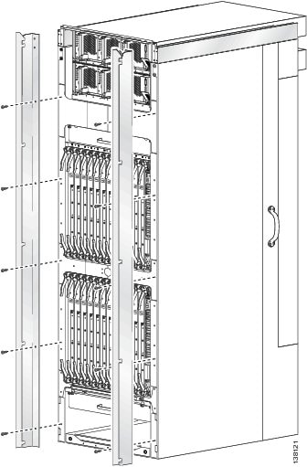
4. Attach the front vertical cable troughs—one on the right and one on the left—to the front (SFC) side of the chassis (see the figure below) by i nserting the 10 M4x14-mm flat head screws (5 on each side). Use the screwdriver to fasten screws to attach the cable troughs firmly to the chassis.
5. Attach the front upper grille (optional) by carefully inserting the tabs on the grille into the hook hanger brackets on the top of the upper grille support (see the figure below).
6. Press the grille firmly against the grille support until it snaps onto the ball stud snaps on the front (SFC) side of the chassis.
7. Place the logo bezel (see the figure below) over the bezel support, and press firmly until the bezel snaps onto the ball stud snaps on the front (SFC) side of the chassis.
8. Using the screwdriver, loosen the four captive screws, two on each side, that secure the lower grille screen to its frame assembly; then carefully set the screen aside. See the figure below.
9. Attach the frame assembly to the chassis (see the figure below) by aligning the four screws, two on each side, on the frame to the screw holes on the chassis and tightening them with the screwdriver.
10. Reattach the inlet grille screen (see the above figure) to the frame assembly by aligning the four captive screws on the screen to the screw holes on the frame assembly and tightening the screws with the screwdriver.
11. Attach the lower grille to the chassis by carefully inserting the tabs on the grille into the hook hanger brackets. See the figure below.
12. Press the lower grille firmly until it snaps onto the ball stud snaps. See the figure below.
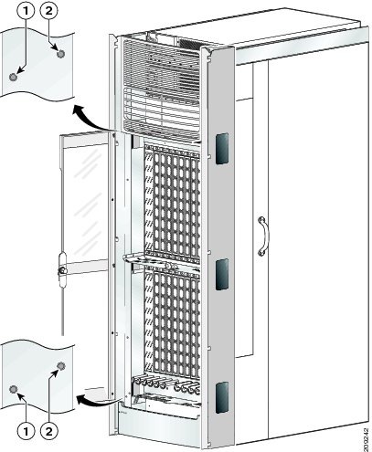
13. Orient the doors so that the keyhole slots are pointing upwards.
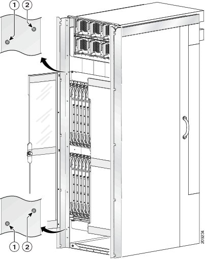
14. Align the doors vertically in their appropriate positions so you can determine where to thread the first two screws that are adjacent to the keyholes. See the figure below. Set the doors aside, and thread the two screws.
15. Place the doors on the screws in the keyhole positions, two for each door.
16. Insert four M4x8-mm wafer-head screws (two on each side) into the appropriate screw holes in the doors, and use the screwdriver to tighten fully.
17. Insert and fully tighten all screws.
18. Ensure that the doors are properly aligned.
DETAILED STEPS
Removing the Front (SFC) Side Cosmetic Components
This section describes how to remove the front (SFC) side exterior cosmetic components, shown in Figure 1, from the chassis. This section includes all the steps for you to remove all the front cosmetic parts from the chassis, but you are not required to do so. To remove a particular part, see the appropriate step or steps in the procedure that follows.
Note | While it is possible to remove most of the front cosmetic components on the FCC separately, some parts (such as a unistrut) require that other parts be removed first. |
This section describes how to perform the following tasks:
Prerequisites
No prerequisites exist for this task.
Required Tools and Equipment
You need the following tools to perform this task:
- 8-in. long number 1 Phillips screwdriver—magnetic head preferable
- 10-mm hex key wrench
Steps
To remove the front (SFC) side external cosmetic components, perform the following steps:
1. Ensure that you have all the original packaging material for the cosmetic components available.
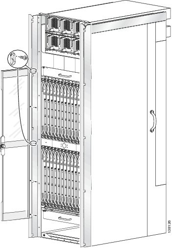
2. Remove the front exterior doors by unscrewing all the screws except those adjacent to the keyholes (see the figure below); lift the doors, and set them carefully aside.
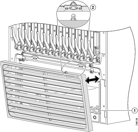
3. Remove the front lower grille (see the figure below) by unsnapping the top portion from the ball stud snaps on the grille frame.
4. Rotate the grille toward you on its hook hanger brackets, then lift it clear of the support, and set it carefully aside.
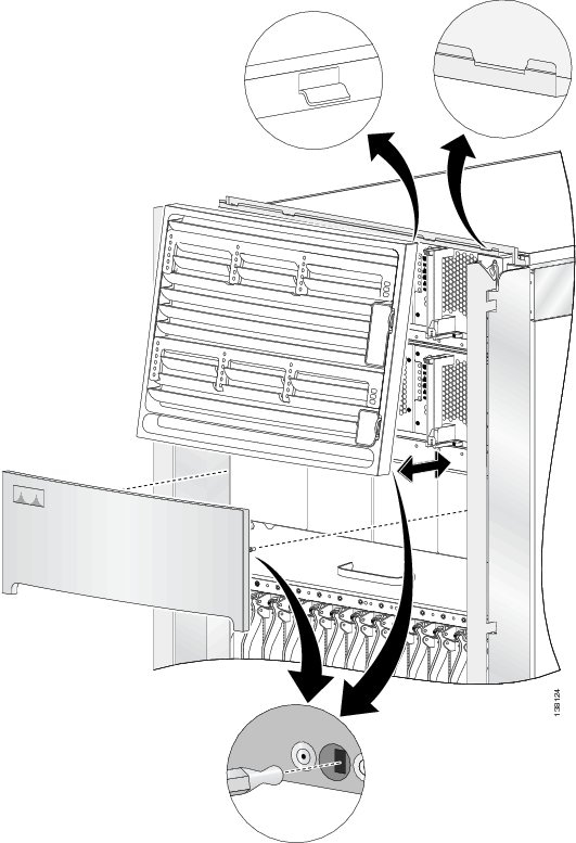
5. Remove the logo bezel (see the figure below) by unsnapping it from the ball stud snaps on either side of the bezel support, and then set it carefully aside.
6. Remove the upper grille (see the figure below) by unsnapping the bottom portion from the ball stud snaps on the logo bezel support assembly.
7. Rotate the grille toward you on its hook hanger brackets, then lift it clear of the support, and set it carefully aside.
8. Remove the front vertical cable troughs (see the figure below)—one right and one left—from the front (SFC) of the chassis:
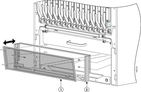
9. Use the screwdriver to loosen the four captive screws, two on each side, that attach the inlet grille screen to the frame assembly. Remove the screen from the frame assembly. See the figure below.
10. Remove the four screws, two on each side, that attach the frame assembly to the chassis. See the figure below.
11. Rotate the assembly forward, lift it away from the front (SFC) side of the chassis, and set it aside.
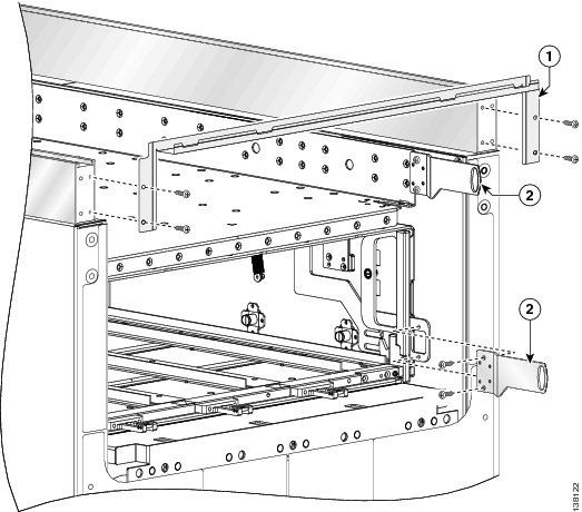
12. Remove the power shelf shutoff extenders (number 2 in the figure below) by unscrewing the four screws, two screws per extender, and set the screws and the extenders aside.
13. Remove the front upper grille support (number 1 in the figure below) from the unistruts by unscrewing the four M4x14-mm flat head screws (two for each unistrut).
14. Set the screws aside, then lift the grille support away from the front (SFC) side of the chassis, and set it aside.
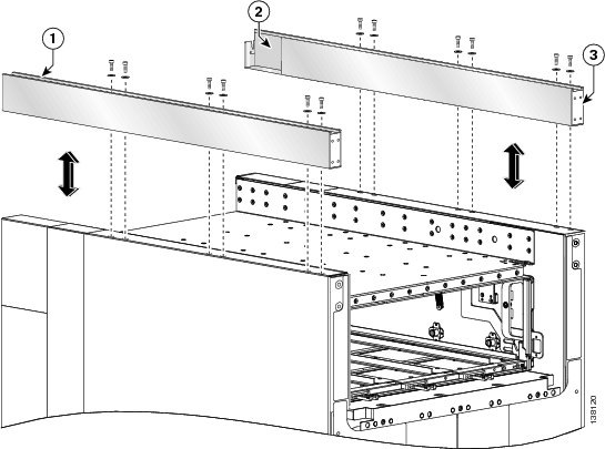
15. Use the 10-mm hex key wrench to remove the twelve M12 hex head bolts and washers, six on each unistrut, that attach the unistrut to the top of the chassis. See the figure below.
DETAILED STEPS
| Step 1 | Ensure that you have all the original packaging material for the cosmetic components available. | ||||||||
| Step 2 | Remove the
front exterior doors by unscrewing all the screws except those adjacent to the
keyholes (see the figure below); lift the doors, and set them carefully aside.
 | ||||||||
| Step 3 | Remove the front lower grille (see the figure below) by unsnapping the top portion from the ball stud snaps on the grille frame. | ||||||||
| Step 4 | Rotate the
grille toward you on its hook hanger brackets, then lift it clear of the
support, and set it carefully aside.
| ||||||||
| Step 5 | Remove the logo bezel (see the figure below) by unsnapping it from the ball stud snaps on either side of the bezel support, and then set it carefully aside. | ||||||||
| Step 6 | Remove the upper grille (see the figure below) by unsnapping the bottom portion from the ball stud snaps on the logo bezel support assembly. | ||||||||
| Step 7 | Rotate the
grille toward you on its hook hanger brackets, then lift it clear of the
support, and set it carefully aside.
 | ||||||||
| Step 8 | Remove the
front vertical cable troughs (see the figure below)—one right and one left—from
the front (SFC) of the chassis:
| ||||||||
| Step 9 | Use the screwdriver to loosen the four captive screws, two on each side, that attach the inlet grille screen to the frame assembly. Remove the screen from the frame assembly. See the figure below. | ||||||||
| Step 10 | Remove the four
screws, two on each side, that attach the frame assembly to the chassis. See
the figure below.
| ||||||||
| Step 11 | Rotate the assembly forward, lift it away from the front (SFC) side of the chassis, and set it aside. | ||||||||
| Step 12 | Remove the power shelf shutoff extenders (number 2 in the figure below) by unscrewing the four screws, two screws per extender, and set the screws and the extenders aside. | ||||||||
| Step 13 | Remove the front upper grille support (number 1 in the figure below) from the unistruts by unscrewing the four M4x14-mm flat head screws (two for each unistrut). | ||||||||
| Step 14 | Set the screws
aside, then lift the grille support away from the front (SFC) side of the
chassis, and set it aside.
| ||||||||
| Step 15 | Use the 10-mm
hex key wrench to remove the twelve M12 hex head bolts and washers, six on each
unistrut, that attach the unistrut to the top of the chassis. See the figure
below.
|
What to Do Next
Be sure that all parts have been carefully set aside and repackaged appropriately.
Installing the Rear (OIM) Side Cosmetic Components
This section describes how to install the rear (OIM) side exterior cosmetic components, shown in Figure 2, on the FCC.
Note | While it is possible to install the various exterior components on the chassis in a different order, it is easier to install them in the order outlined in this section. |
This section describes how to perform the following tasks:
Prerequisites
Before performing these tasks, you must first unpack and secure the chassis. See Cisco CRS Carrier Routing System Fabric Card Chassis Unpacking, Moving, and Securing Guide .
Required Tools and Equipment
You need the following tools and part to perform this task:
- 8-inch long number 1 Phillips screwdriver—magnetic head preferable
- 2-mm hex key wrench
- Rear cosmetic kit (Cisco product number: CRS-FCC-REAR-CM=)
- Rear doors (Cisco product number: CRS-FCC-DRS-RR=)
Steps
To install the rear exterior cosmetic components, perform the following steps:
1. Ensure that the unistruts are installed. See the Steps.
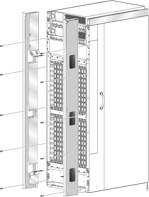
2. Attach the rear vertical cable troughs —one right and one left—to the rear of the chassis (as shown in the figure below) by i nserting the 10 M4x14-mm flat head screws (5 on each side) and using the screwdriver to fasten the screws to attach the cable troughs firmly to the chassis.
3. If applicable, remove blank covers and install cable pass-through accessory plates.
4. Remove the blank plates by unscrewing the four screws on each one. See the figure below.
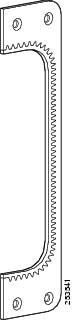
5. Attach the inner cut-out plates, as shown in the figure below, using the four screws provided. See the figure Inner Cut-out Plate—Fixed Configuration Power Shown.
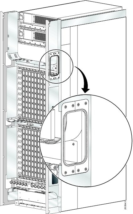
6. Attach the outer cut-out panel using the screws provided. See the figure below.
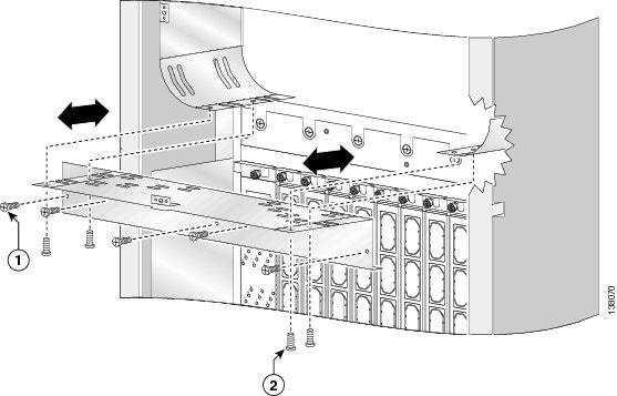
7. Attach the rear upper horizontal cable guides (see the figure below) by inserting five longer Phillips screws through the holes in the face of the brackets and into the chassis and tightening them to the chassis with the screwdriver.
8. Insert the four short Phillips screws (two on each side) that attach the bracket to the vertical cable trough support flange and tighten them to the troughs with the screwdriver.
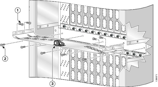
9. Attach the rear mid-chassis horizontal cable guide and strike tube (see the figure below) by inserting the five longer Phillips screws through the holes in the face of the brackets and into the rear (OIM) side of the chassis and tightening them to the chassis with the screwdriver.
10. Insert the four short Phillips screws (two on each side) that attach the bracket to the inside of the vertical cable troughs, and tighten them to the troughs with the screwdriver.
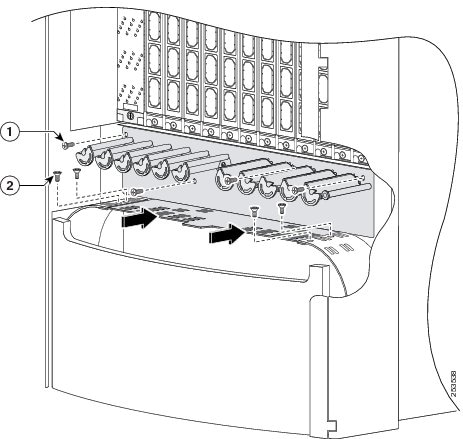
11. Attach the rear lower horizontal cable guides (see the figure below) by inserting four longer Phillips screws through the holes in the face of the brackets and into the chassis and tightening them to the chassis with the screwdriver.
12. Insert the four short Phillips screws (two on each side) that attach the bracket to the vertical cable trough support flanges and tighten them to the troughs with the screwdriver.
13. Attach the rear upper grille by carefully hooking the tabs on the top of the grille over the hook supports on the top of the vertical cable troughs (see the figure below).
14. Press the grille firmly against the grille support until it snaps onto the ball stud snaps on the rear (OIM) side of the chassis.
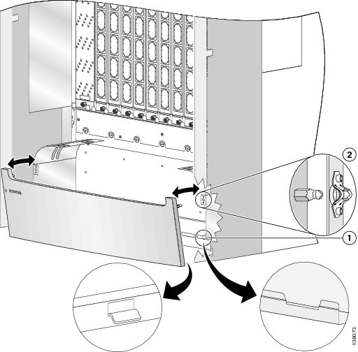
15. Attach the rear lower bezel by carefully inserting the tabs on the grille into the hook hanger brackets on the lower bezel frame. Press the grille firmly against the grille frame until it snaps onto the ball stud snaps on the rear (OIM) side of the chassis (see see the figure below).
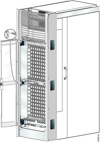
16. Orient the doors so that the keyhole slots are pointing up.
17. Align the doors vertically in their appropriate positions so you can determine where to thread the first two screws that are adjacent to the keyholes. See the figure below. Set the doors aside, and thread the two screws.
18. Place the doors on the screws in the keyhole positions, two for each door.
19. Insert four M4x8-mm wafer-head screws (two on each side) into the appropriate screw holes in the doors, and use the screwdriver to fully tighten.
20. Insert and fully tighten all screws.
21. Ensure that the doors are properly aligned.
DETAILED STEPS
| Step 1 | Ensure that the unistruts are installed. See the Steps. | ||||||||
| Step 2 | Attach the rear
vertical cable troughs —one right and one left—to the rear of the chassis (as
shown in the figure below) by i nserting the 10 M4x14-mm flat head screws (5 on
each side) and using the screwdriver to fasten the screws to attach the cable
troughs firmly to the chassis.
| ||||||||
| Step 3 | If applicable,
remove blank covers and install cable pass-through accessory plates.
 System growth and cable type will determine whether cable pass-through accessory plates are required to be installed.
| ||||||||
| Step 4 | Remove the
blank plates by unscrewing the four screws on each one. See the figure below.
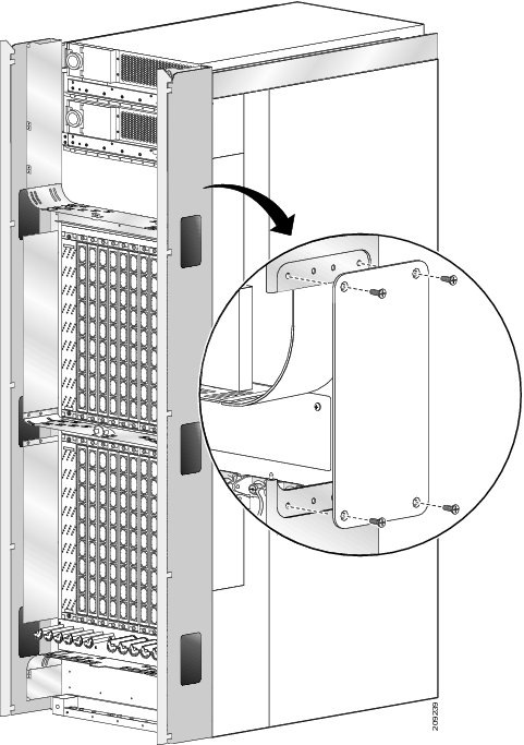 | ||||||||
| Step 5 | Attach the
inner cut-out plates, as shown in the figure below, using the four screws
provided. See the figure
Inner
Cut-out Plate—Fixed Configuration Power Shown.
 | ||||||||
| Step 6 | Attach the
outer cut-out panel using the screws provided. See the figure below.
| ||||||||
| Step 7 | Attach the rear
upper horizontal cable guides (see the figure below) by inserting five longer
Phillips screws through the holes in the face of the brackets and into the
chassis and tightening them to the chassis with the screwdriver.
| ||||||||
| Step 8 | Insert the four short Phillips screws (two on each side) that attach the bracket to the vertical cable trough support flange and tighten them to the troughs with the screwdriver. | ||||||||
| Step 9 | Attach the rear
mid-chassis horizontal cable guide and strike tube (see the figure below) by
inserting the five longer Phillips screws through the holes in the face of the
brackets and into the rear (OIM) side of the chassis and tightening them to the
chassis with the screwdriver.
| ||||||||
| Step 10 | Insert the four short Phillips screws (two on each side) that attach the bracket to the inside of the vertical cable troughs, and tighten them to the troughs with the screwdriver. | ||||||||
| Step 11 | Attach the rear
lower horizontal cable guides (see the figure below) by inserting four longer
Phillips screws through the holes in the face of the brackets and into the
chassis and tightening them to the chassis with the screwdriver.
| ||||||||
| Step 12 | Insert the four short Phillips screws (two on each side) that attach the bracket to the vertical cable trough support flanges and tighten them to the troughs with the screwdriver. | ||||||||
| Step 13 | Attach the
rear upper grille by carefully hooking the tabs on the top of the grille over
the hook supports on the top of the vertical cable troughs (see the figure
below).
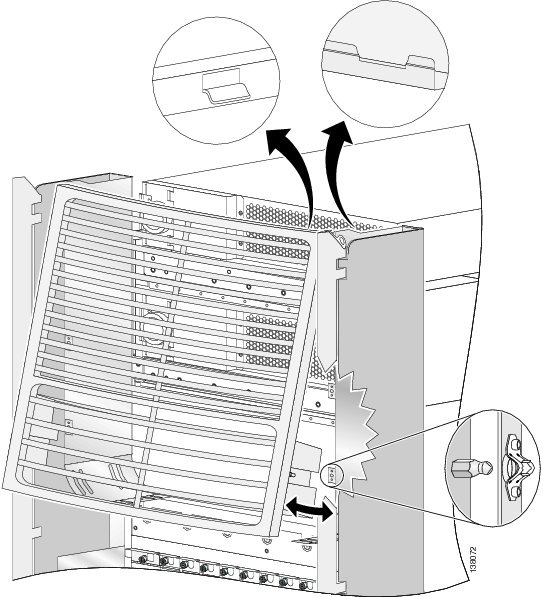 | ||||||||
| Step 14 | Press the grille firmly against the grille support until it snaps onto the ball stud snaps on the rear (OIM) side of the chassis. | ||||||||
| Step 15 | Attach the
rear lower bezel by carefully inserting the tabs on the grille into the hook
hanger brackets on the lower bezel frame. Press the grille firmly against the
grille frame until it snaps onto the ball stud snaps on the rear (OIM) side of
the chassis (see see the figure below).
| ||||||||
| Step 16 | Orient the
doors so that the keyhole slots are pointing up.
| ||||||||
| Step 17 | Align the
doors vertically in their appropriate positions so you can determine where to
thread the first two screws that are adjacent to the keyholes. See the figure
below. Set the doors aside, and thread the two screws.
 | ||||||||
| Step 18 | Place the doors on the screws in the keyhole positions, two for each door. | ||||||||
| Step 19 | Insert four
M4x8-mm wafer-head screws (two on each side) into the appropriate screw holes
in the doors, and use the screwdriver to fully tighten.
| ||||||||
| Step 20 | Insert and fully tighten all screws. | ||||||||
| Step 21 | Ensure that
the doors are properly aligned.
|
What to Do Next
After performing this task, insert the rear horizontal Velcro cable bracket straps and install cabling that connects the FCC to the other components in the multishelf system. See the Cisco CRS Carrier Routing System Multishelf System Interconnection and Cabling Guide for more information.
This section describes how to remove the rear (OIM) side exterior cosmetic components, shown in Figure 2, from the FCC. This section includes all the steps for you to remove all the cosmetic parts from your chassis, but you are not required to do so. To remove a particular part, see the appropriate step in the Steps section that follows.
This section describes how to perform the following tasks:
Note | While it is possible to remove most of the rear cosmetic parts on the FCC separately, some parts (such as a unistrut) require that other parts be removed first. |
Prerequisites
Ensure that you have all the original packaging material for the cosmetic components available.
Required Tools and Equipment
You need the following tools to perform this task:
- 8-in. long number 1 Phillips screwdriver—magnetic head preferable
Steps
To remove the rear (OIM) side cosmetic components, perform the following steps:
1. Remove the rear exterior doors by unscrewing all the screws except those adjacent to the keyholes (see the figure below); hold the doors to the chassis, lift the doors, and set them carefully aside.
2. Remove the rear lower bezel (see the figure below) by unsnapping the top portion from the ball stud snaps on the grille frame; rotate the grille toward you on its hook hanger brackets, then lift it clear of the support, and set it carefully aside.
3. Remove the rear upper grille (see the figure below) by unsnapping the bottom portion from the ball stud snaps on the logo bezel support assembly; rotate the grille toward you on its hook hanger brackets, then lift it clear of the support, and set it carefully aside.
4. Use the screwdriver to remove the four screws (two on each side) that attach the bracket to the vertical cable trough support flange (see the figure below), and set them aside.
5. Using the screwdriver, remove the five longer Phillips head screws that attach the face of the bracket to the chassis. Remove the cable guide and carefully set it aside. (see the figure below)
6. Use the screwdriver to remove the four flat head Phillips screws, two on each side, that attach the cable guide to the chassis, and set them aside. See the figure below.
7. Using the screwdriver, remove the five flat head Phillips screws that attach the cable guide to the chassis. Remove the cable guide and carefully set it aside. See the figure below.
8. Use the screwdriver to remove the four screws (two on each side) that attach the bracket to the vertical cable trough support flange, and set them aside. See the figure below.
9. Using the screwdriver, remove the four screws that attach the cable guide to the chassis. Remove the cable guide and carefully set it aside. See the figure below.
10. Remove the rear vertical cable troughs —one right and one left— from the rear of the chassis (see the figure below):
DETAILED STEPS
| Step 1 | Remove the rear
exterior doors by unscrewing all the screws except those adjacent to the
keyholes (see the figure below); hold the doors to the chassis, lift the doors,
and set them carefully aside.
| ||||||
| Step 2 | Remove the rear
lower bezel (see the figure below) by unsnapping the top portion from the ball
stud snaps on the grille frame; rotate the grille toward you on its hook hanger
brackets, then lift it clear of the support, and set it carefully aside.
| ||||||
| Step 3 | Remove the rear
upper grille (see the figure below) by unsnapping the bottom portion from the
ball stud snaps on the logo bezel support assembly; rotate the grille toward
you on its hook hanger brackets, then lift it clear of the support, and set it
carefully aside.
| ||||||
| Step 4 | Use the screwdriver to remove the four screws (two on each side) that attach the bracket to the vertical cable trough support flange (see the figure below), and set them aside. | ||||||
| Step 5 | Using the
screwdriver, remove the five longer Phillips head screws that attach the face
of the bracket to the chassis. Remove the cable guide and carefully set it
aside. (see the figure below)
| ||||||
| Step 6 | Use the screwdriver to remove the four flat head Phillips screws, two on each side, that attach the cable guide to the chassis, and set them aside. See the figure below. | ||||||
| Step 7 | Using the
screwdriver, remove the five flat head Phillips screws that attach the cable
guide to the chassis. Remove the cable guide and carefully set it aside. See
the figure below.
| ||||||
| Step 8 | Use the screwdriver to remove the four screws (two on each side) that attach the bracket to the vertical cable trough support flange, and set them aside. See the figure below. | ||||||
| Step 9 | Using the
screwdriver, remove the four screws that attach the cable guide to the chassis.
Remove the cable guide and carefully set it aside. See the figure below.
| ||||||
| Step 10 | Remove the
rear vertical cable troughs —one right and one left— from the rear of the
chassis (see the figure below):
|
What to Do Next
Be sure that all parts have been carefully set aside and repackaged appropriately.
What to Do Next
Be sure that all parts have been carefully set aside and repackaged appropriately.
 Feedback