- Preface
- Overview
- Installing and Removing Power Components
- Installing and Removing Air Circulation Components
- Installing and Removing Fabric Cards and Card Components
- Installing and Removing Exterior Cosmetic Components
- Upgrading Chassis Components
- Cisco CRS-1 Carrier Routing System Fabric Card Chassis Specifications
- Product IDs
Cisco CRS Carrier Routing System Fabric Card Chassis Installation Guide
Bias-Free Language
The documentation set for this product strives to use bias-free language. For the purposes of this documentation set, bias-free is defined as language that does not imply discrimination based on age, disability, gender, racial identity, ethnic identity, sexual orientation, socioeconomic status, and intersectionality. Exceptions may be present in the documentation due to language that is hardcoded in the user interfaces of the product software, language used based on RFP documentation, or language that is used by a referenced third-party product. Learn more about how Cisco is using Inclusive Language.
- Updated:
- February 15, 2017
Chapter: Installing and Removing Fabric Cards and Card Components
- Information About Installing and Removing Cards and Associated Components
- How to Install and Remove Cards and Associated Components
- Removing the Card Cage Cover Plate
- Installing an Impedance Carrier
- Removing an Impedance Carrier
- Installing a Slot Cover
- Removing a Slot Cover
- Installing a Pillow Block
- Removing a Pillow Block
- Installing an OIM Impedance Carrier
- Removing an OIM Impedance Carrier
- Installing an OIM
- Removing an OIM
- Installing an OIM LED Module
- Removing an OIM LED Module
- Installing an SFC
- Removing an SFC
- Verifying the Installation of an SFC
- Installing an SCGE Card
- Removing an SCGE Card
- Verifying the Installation of an SCGE Card
- Installing a PCMCIA Card Into an SCGE Card
- Removing a PCMCIA Card From the SCGE Card
Installing and Removing Fabric Cards and Card Components
This chapter provides instructions on how to install and remove the Cisco CRS Carrier Routing System Fabric Card Chassis (FCC) cards and card components.
This chapter presents the following topics:
- Information About Installing and Removing Cards and Associated Components
- How to Install and Remove Cards and Associated Components
Information About Installing and Removing Cards and Associated Components
This section contains some general information about the cards and card components in the following sections:
- Guidelines for Card Installation and Removal
- Information About Card and Optical Interface Module (OIM) Installation Order
- Information About Impedance Carriers, Slot Covers,OIM Impedance Carriers, and Card Cage Cover Plates
- Information About PCMCIA Cards
Guidelines for Card Installation and Removal
Guidelines for card installation and removal include the following:
- Online (in-service) insertion and removal (OIR) is supported, enabling you to remove and install cards while the router is operating. You must shut down the controller fabric plane and the card itself to safely remove or insert a card in a running system. See the software documentation for information on the shutdown command.
- The different cards in the FCC are all attached to the chassis itself using a pair of ejector levers and captive screws. The two ejector levers are used to release the card from its backplane (and associated OIM) connectors. The exact location of the ejector levers and captive screws varies slightly from card to card, but are, in general, in the same location: on the upper and bottom ends of the card faceplate. The figure below shows the location of the ejector levers and captive screws (on an SFC).
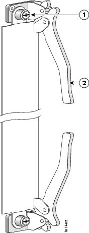
|
1 |
Captive screw |
2 |
Ejector lever |
The figure below shows how to operate the ejector levers. Be sure to operate both levers simultaneously.
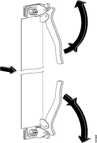
 Caution | When you remove a card, always use the ejector levers to ensure that the connector pins disconnect from the backplane in the sequence expected by the router. |
Caution | The router may indicate a hardware failure if you do not follow proper procedures. Remove or install only one card at a time. Allow at least 15 seconds for the router to complete the preceding tasks before removing or installing another card. |
Information About Card and Optical Interface Module (OIM) Installation Order
The FCC contains two card cages; each card cage contains 12 slots for the SFCs and an additional slot for the shelf controller Gigabit Ethernet (SCGE) card (see figure below on FCC Front (SFC) Side Slot Numbers). Each OIM associated with an SFC has 9 optical bulkhead array connectors. The SFCs and SCGEs are installed in the front (SFC) side of the chassis; the OIMs are installed in the rear.
 Note | Be sure to install the OIMs before the SFCs; otherwise, you will be unable to install the OIM. |
You need one 22-port SCGE card for each card cage; the SCGE is installed in the far right slot (as you are facing the front [SFC] side of the chassis) of the top or bottom card cage.
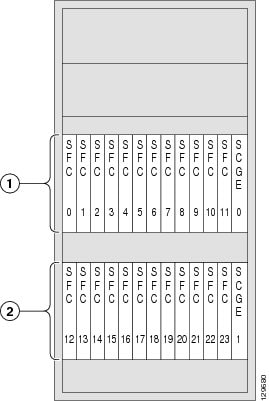
|
1 |
Upper card cage |
2 |
Lower card cage |
As shown in the figure above, the FCC numbers on the front (SFC) side of the chassis include:
- Upper card cage with 12 switch fabric slots (left to right: 0, 1, 2, 3. . . 10, 11) followed by one 22-port SCGE card slot (SCGE0) on the far right.
- Lower card cage with 12 switch fabric slots (left to right: 12, 13, 14 . . . 21, 22, 23) followed by one 22-port SCGE card slot (SCGE1) on the far right.
See this figure for the FCC slot numbers on the rear (OIM) side of the chassis.
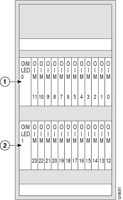
|
1 |
Upper card cage |
2 |
Lower card cage |
As shown in above figure, slot numbers on the OIM side of the chassis include:
- OIM side of upper card cage, with one OIM LED module (LM0) on the far left, followed by 12 OIM slots (left to right: 11, 10, 9 . . . 2, 1, 0).
- OIM side of lower card cage, with one OIM LED module (LM1) on the far left, followed by 12 OIM slots (left to right: 23, 22, 21 . . . 14, 13, 12).
The OIM slot numbers match their corresponding SFC slot numbers on the other side of the chassis; OIM slot 0 is on the far right of the rear of the chassis (matching SFC slot 0 on the far left of the front of the chassis).
Caution | For proper chassis airflow, all slots need to be populated with a card or an impedance carrier. We recommend removing or inserting one card at a time. Allow at least 15 seconds for the router to complete the preceding tasks before removing or installing another card. (See Information About Impedance Carriers, Slot Covers,OIM Impedance Carriers, and Card Cage Cover Plates) |
The FCC is equipped with two card cages, each of which is divided into two power zones, making four total chassis power zones.
For detailed information about how to install cards in the chassis to ensure high availability, see the Cisco CRS Carrier Routing System Multishelf System Site Planning Guide .
Information About Impedance Carriers, Slot Covers,OIM Impedance Carriers, and Card Cage Cover Plates
For safety and to help maintain chassis stiffness, the chassis is shipped with both the upper and lower card cages covered with cover plates (see the following figure).
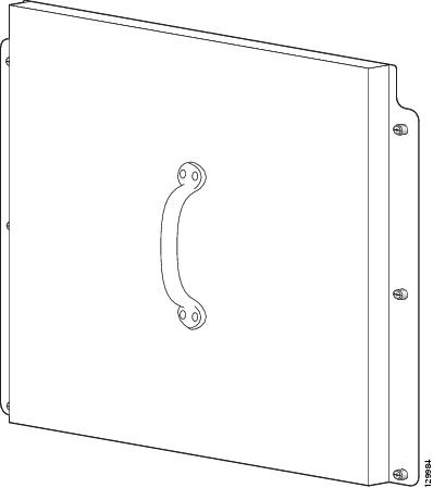
You should leave the card cage cover plates in place while moving and securing the chassis; remove the plates only when you are ready to begin installing the cards in the chassis. See the Removing the Card Cage Cover Plate.
No SFC or OIM slots are empty during chassis shipment.
- The chassis is shipped with impedance carriers (see figure, SFC Slot Impedance Carrier) installed in all SFC slots except 0, 3, 6, 9, 12, 15, 18, and 21.
- The chassis is shipped with slot covers (see figure, SFC Slot Cover) over slots 0, 3, 6, 9, 12, 15, 18, and 21.
The following figure shows the SFC slot impedance carrier. For information on installing and removing the impedance carriers, see Installing an Impedance Carrier and Removing an Impedance Carrier.
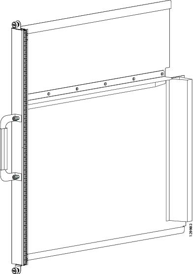
The following figure shows the SFC slot cover. For information on installing and removing the impedance carriers, see Installing a Slot Cover and Removing a Slot Cover.

The chassis is shipped with OIM impedance carriers (see figure, OIM Impedance Carrier) in all OIM slots on the rear (OIM) side of the chassis. For information on installing and removing the OIM impedance carriers, see the Installing an OIM Impedance Carrier and the Removing an OIM Impedance Carrier.

To provide the chassis with proper cooling and help maintain stiffness, we recommend that you leave the cover plates and impedance carriers in place until you are ready to install the SFCs.
Note | Do not leave blank slots in the chassis. All slots must be covered using impedance cards or blanks. |
Information About PCMCIA Cards
The SCGE card provides two PCMCIA flash slots that each provide up to 1 GB of flash storage. One PCMCIA flash subsystem is accessible externally, is removable, and allows you to transfer images and configurations by plugging in a PCMCIA flash card. The other subsystem is fixed to the SCGE card, not removable, and is for permanent storage of configurations and images.
How to Install and Remove Cards and Associated Components
This section contains the following procedures:
- Removing the Card Cage Cover Plate
- Installing an Impedance Carrier
- Removing an Impedance Carrier
- Installing a Slot Cover
- Removing a Slot Cover
- Installing a Pillow Block
- Removing a Pillow Block
- Installing an OIM Impedance Carrier
- Removing an OIM Impedance Carrier
- Installing an OIM
- Removing an OIM
- Installing an OIM LED Module
- Removing an OIM LED Module
- Installing an SFC
- Removing an SFC
- Verifying the Installation of an SFC
- Installing an SCGE Card
- Removing an SCGE Card
- Verifying the Installation of an SCGE Card
- Installing a PCMCIA Card Into an SCGE Card
- Removing a PCMCIA Card From the SCGE Card
Removing the Card Cage Cover Plate
This section describes how to remove the card cage cover plates from the FCC. This figure shows the cover plate that is installed over both the upper and lower card cages to provide additional stability and safety during shipment.
Prerequisites
Before performing this task, make sure that you have moved the chassis into its final location and secured it to the floor. For details, see Unpacking, Moving, and Securing the Cisco CRS Carrier Routing System Fabric Card Chassis .
Tools and Equipment
You need the following tools to remove a card cage cover plate:
- ESD-preventative wrist strap
- 6-in. long number 1 Phillips screwdriver
Steps
To remove a card cage cover plate, perform the following steps:
1. Attach the ESD-preventive wrist strap to your wrist and connect its leash to an ESD connection socket on the front (SFC) side of the chassis or to a bare metal surface on the chassis.
2. Use the screwdriver to loosen the bottom four captive screws (two for each side) on the upper card cage cover plate.
3. While holding the handle firmly, loosen the remaining two screws (one for each side) that attach the cover plate to the chassis.
4. Set the cover plate carefully aside.
5. Repeat the procedure for the lower cover plate.
DETAILED STEPS
| Step 1 | Attach the ESD-preventive wrist strap to your wrist and connect its leash to an ESD connection socket on the front (SFC) side of the chassis or to a bare metal surface on the chassis. | ||
| Step 2 | Use the screwdriver to loosen the bottom four captive screws (two for each side) on the upper card cage cover plate. | ||
| Step 3 |
While holding the handle firmly, loosen the remaining two screws (one for each side) that attach the cover plate to the chassis.
| ||
| Step 4 | Set the cover plate carefully aside. | ||
| Step 5 | Repeat the procedure for the lower cover plate. |
What to Do Next
After performing this task, you may install any card cage components. See the Installing an SFC and the Installing an SCGE Card.
Installing an Impedance Carrier
This section describes how to install an impedance carrier in the FCC. The chassis is shipped with impedance carriers installed (see the following figure) in all SFC slots except 0, 3, 6, 9, 12, 15, 18, and 21 (see the Information About Card and Optical Interface Module (OIM) Installation Order). For more detailed information on impedance carriers, see the Information About Impedance Carriers, Slot Covers,OIM Impedance Carriers, and Card Cage Cover Plates.
This figure shows an SFC slot impedance carrier.
Prerequisites
Before performing this task, open the cosmetic doors (if installed) and ensure that the slot in which you are about to install the impedance carrier is empty. See the Information About Impedance Carriers, Slot Covers,OIM Impedance Carriers, and Card Cage Cover Plates and either the Removing an SFC or the Removing an SCGE Card (depending on the slot in which you are installing an impedance carrier).
Required Tools and Equipment
You need the following tools and part to install an impedance carrier:
- ESD-preventive wrist strap
- 6-in. long number 1 Phillips screwdriver
- Impedance carrier (Cisco Product number CRS-SFC-IMPEDANCE=)
Steps
To install an impedance carrier, perform the following steps:
1. Attach the ESD-preventive wrist strap to your wrist and connect its leash to an ESD connection socket on the front (SFC) side of the chassis or to a bare metal surface on the chassis.
2. Use both hands while inserting an impedance carrier. Use one hand on the faceplate and the other hand along the base of the impedance carrier to guide it into a slot.
3. Slide the impedance carrier into the chassis until the captive screw plates are flush with the chassis.
4. Partially tighten the two captive screws on the front panel of the impedance carrier (either by hand or with the screwdriver) to make sure that they are both engaged.
5. Use the screwdriver to fully tighten the captive screws to seat the impedance carrier firmly in the slot.
DETAILED STEPS
| Step 1 | Attach the ESD-preventive wrist strap to your wrist and connect its leash to an ESD connection socket on the front (SFC) side of the chassis or to a bare metal surface on the chassis. |
| Step 2 | Use both hands while inserting an impedance carrier. Use one hand on the faceplate and the other hand along the base of the impedance carrier to guide it into a slot. |
| Step 3 | Slide the impedance carrier into the chassis until the captive screw plates are flush with the chassis. |
| Step 4 | Partially tighten the two captive screws on the front panel of the impedance carrier (either by hand or with the screwdriver) to make sure that they are both engaged. |
| Step 5 | Use the screwdriver to fully tighten the captive screws to seat the impedance carrier firmly in the slot. |
What to Do Next
After performing this task, you may close the doors on the front (SFC) side of the chassis (if installed). For more information, see the How to Install and Remove Cards and Associated Components.
Removing an Impedance Carrier
This section describes how to remove an impedance carrier from the FCC. The chassis is shipped with impedance carriers installed (see Figure 1) in all SFC slots except 0, 3, 6, 9, 12, 15, 18, and 21 (see the Information About Card and Optical Interface Module (OIM) Installation Order). For more detailed information on impedance carriers, see the Information About Impedance Carriers, Slot Covers,OIM Impedance Carriers, and Card Cage Cover Plates.
Figure 1 shows an SFC slot impedance carrier.
Prerequisites
Before performing this task open the cosmetic doors (if installed).
Required Tools and Equipment
You need the following tools to perform this task:
- ESD-preventive wrist strap
- 6-in. long number 1 Phillips screwdriver
Steps
To remove an impedance carrier, perform the following steps:
1. Attach the ESD-preventive wrist strap to your wrist and connect its leash to an ESD connection socket on the front (SFC) side of the chassis or to a bare metal surface on the chassis.
2. Identify the impedance carrier to be removed from the card cage. Use the screwdriver to turn the two captive screws on the front panel of the card counterclockwise to loosen it from the slot.
3. Grasp the impedance carrier handle with one hand and gently pull it halfway from the slot.
4. Place one hand under the impedance carrier to guide it.
5. Holding the impedance carrier underneath and by the handle, pull it from the slot and set it carefully aside.
DETAILED STEPS
| Step 1 | Attach the ESD-preventive wrist strap to your wrist and connect its leash to an ESD connection socket on the front (SFC) side of the chassis or to a bare metal surface on the chassis. |
| Step 2 | Identify the impedance carrier to be removed from the card cage. Use the screwdriver to turn the two captive screws on the front panel of the card counterclockwise to loosen it from the slot. |
| Step 3 | Grasp the impedance carrier handle with one hand and gently pull it halfway from the slot. |
| Step 4 | Place one hand under the impedance carrier to guide it. |
| Step 5 | Holding the impedance carrier underneath and by the handle, pull it from the slot and set it carefully aside. |
What to Do Next
After performing this task, store the impedance carrier for future use. You may now install an OIM in the corresponding slot. See the Installing an OIM, the Installing an OIM LED Module, the Installing an SFC, and the Installing an SCGE Card for further details.
Installing a Slot Cover
This section describes how to install a slot cover (see the following figure) in the FCC. The chassis is shipped with slot covers over SFC slots 0, 3, 6, 9, 12, 15, 18, and 21; all other slots are shipped with impedance carriers. For more detailed information on the slot covers, see the Information About Impedance Carriers, Slot Covers,OIM Impedance Carriers, and Card Cage Cover Plates.
Prerequisites
Before performing this task, open the front (SFC) side cosmetic doors (if installed) and remove the card cage cover plate (if necessary), and ensure that the slot over which you are about to install the cover is empty. See the Removing the Card Cage Cover Plate and the Removing an SFC.
Required Tools and Equipment
You need the following tools and part to perform this task:
- ESD-preventive wrist strap
- 6-in. long number 1 Phillips screwdriver
- Slot cover
Steps
To install a slot cover, perform the following steps:
1. Attach the ESD-preventive wrist strap to your wrist and connect its leash to an ESD connection socket on the front (SFC) side of the chassis or to a bare metal surface on the chassis.
2. Hold the slot cover in place over the slot.
3. Partially tighten the two captive screws on the front panel of the slot cover (either by hand or with the screwdriver) to make sure that they are both engaged.
4. Use the screwdriver to fully tighten the captive screws to seat the slot cover firmly in place.
DETAILED STEPS
| Step 1 | Attach the ESD-preventive wrist strap to your wrist and connect its leash to an ESD connection socket on the front (SFC) side of the chassis or to a bare metal surface on the chassis. |
| Step 2 | Hold the slot cover in place over the slot. |
| Step 3 | Partially tighten the two captive screws on the front panel of the slot cover (either by hand or with the screwdriver) to make sure that they are both engaged. |
| Step 4 | Use the screwdriver to fully tighten the captive screws to seat the slot cover firmly in place. |
What to Do Next
After performing this task, you may close the doors on the front (SFC) side of the chassis (if installed). For more information, see How to Install and Remove Cards and Associated Components.
Removing a Slot Cover
This section describes how to remove a slot cover (see Figure 1) from the FCC. The chassis is shipped with slot covers over SFC slots 0, 3, 6, 9, 12, 15, 18, and 21; all other slots are shipped with impedance carriers. For more detailed information on the slot covers, see the Information About Impedance Carriers, Slot Covers,OIM Impedance Carriers, and Card Cage Cover Plates.
Prerequisites
Before performing this task, open the front (SFC) side cosmetic doors (if installed).
Required Tools and Equipment
You need the following tools to perform this task:
- ESD-preventive wrist strap
- 6-in. long number 1 Phillips screwdriver
Steps
To remove a slot cover, perform the following steps:
1. Attach the ESD-preventive wrist strap to your wrist and connect its leash to an ESD connection socket on the front (SFC) side of the chassis or to a bare metal surface on the chassis.
2. Use the screwdriver to loosen the two captive screws that attach the slot cover to the chassis.
3. Remove the slot cover and set it carefully aside.
DETAILED STEPS
| Step 1 | Attach the ESD-preventive wrist strap to your wrist and connect its leash to an ESD connection socket on the front (SFC) side of the chassis or to a bare metal surface on the chassis. |
| Step 2 | Use the screwdriver to loosen the two captive screws that attach the slot cover to the chassis. |
| Step 3 | Remove the slot cover and set it carefully aside. |
What to Do Next
After performing this task, store the slot cover for later reuse. You may now install a card in the uncovered slot. See the Installing an SFC for further details.
Installing a Pillow Block
This section describes how to install a replacement pillow block on the chassis after removing a damaged pillow block. A pillow block is a bracket with a pin that is attached to the chassis above and below each card slot. When you install or remove a card from the chassis, the card ejector levers hook into the pillow blocks above and below the card slot to secure the cards to the slot and allow you to install and remove the cards.
Prerequisites
Before performing this task, you must first open the front cosmetic doors (if installed). Have the pillow block replacement kit (Cisco product number: CRS-PILLBLK=) at hand.
Required Tools and Equipment
You need the following tools and parts to perform this task:
The following items are included in the CRS-PILLBLK= pillow block replacement kit:
- 2 replacement pillow blocks
- 6 Torx-head screws
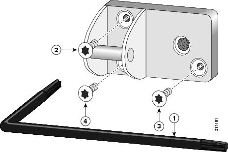
- 1 T10 Torx key (See item 1 in Figure 1.)
Steps
To install a pillow block, perform the following steps:
1. Attach the ESD-preventive wrist strap to your wrist and connect its leash to one of the ESD connection sockets on the front (SFC) side of the chassis or a bare metal surface on the chassis.
2. Locate the slot where the pillow block was removed.
3. Have the replacement T10 Torx-head screws near at hand.
4. Position the pillow block and align the screw holes.
5. Use the T10 Torx key to install the top left screw (located above the pillow block pin). (See item number 2 in the figure below.)
6. Install the lower right screw (see item number 3 in the above figure).
7. Install the lower left screw (located below the pillow block pin). (See item number 4 in the above figure.)
8. Repeat this procedure for the card slot’s other pillow block if necessary.
DETAILED STEPS
What to Do Next
After performing this task, you may close the doors on the front (SFC) side of the chassis (if installed). For more information, see the How to Install and Remove Cards and Associated Components.
Removing a Pillow Block
This section describes how to remove a damaged pillow block from the chassis. A pillow block is a bracket with a pin that is attached to the chassis above and below each card slot. When you install or remove a card from the chassis, the card ejector levers hook into the pillow blocks above and below the card slot to secure the cards to the slot and allow you to install and remove the cards.
Prerequisites
Before performing this task, you must first open the front cosmetic doors (if installed). Have the pillow block replacement kit (Cisco product number: CRS-PILLBLK=) at hand.
Required Tools and Equipment
You need the following tools and parts to perform this task:
- ESD-preventive wrist strap
- 1 T10 Torx key—included in pillow block replacement kit
Steps
To remove a damaged pillow block, perform the following steps:
1. Attach the ESD-preventive wrist strap to your wrist and connect its leash to one of the ESD connection sockets on the front (SFC) side of the chassis or a bare metal surface on the chassis.
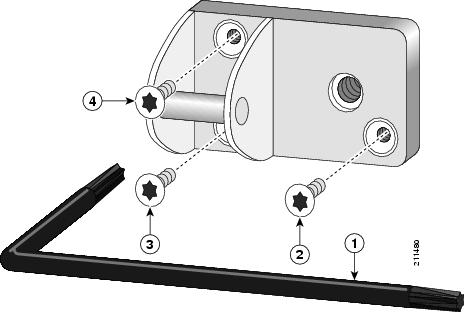
2. Locate the pillow block to be replaced. Use the T10 Torx key to remove the lower right screw. (See item number 2 in the below figure.)
3. Remove the lower left screw (located below the pillow block pin). (See item number 3 in the above figure.)
4. Remove the top left screw (located above the pillow block pin). (See item number 4 in the above figure.)
5. Remove the pillow block and set it aside.
6. Repeat this procedure for the card slot’s other pillow block if necessary.
DETAILED STEPS
| Step 1 | Attach the ESD-preventive wrist strap to your wrist and connect its leash to one of the ESD connection sockets on the front (SFC) side of the chassis or a bare metal surface on the chassis. | ||||||||
| Step 2 | Locate the pillow block to be replaced. Use the T10 Torx key to remove the lower right screw. (See item number 2 in the below figure.)
| ||||||||
| Step 3 | Remove the lower left screw (located below the pillow block pin). (See item number 3 in the above figure.) | ||||||||
| Step 4 | Remove the top left screw (located above the pillow block pin). (See item number 4 in the above figure.) | ||||||||
| Step 5 | Remove the pillow block and set it aside. | ||||||||
| Step 6 | Repeat this procedure for the card slot’s other pillow block if necessary. |
What to Do Next
After performing this task, you may install a new pillow block (see the Installing a Pillow Block).
Installing an OIM Impedance Carrier
This section describes how to install an OIM impedance carrier (see the following figure) in the FCC. The chassis is shipped with an OIM impedance carrier in each OIM slot on the rear (OIM) side of the chassis. For more detailed information on the OIM impedance carriers, see the Information About Impedance Carriers, Slot Covers,OIM Impedance Carriers, and Card Cage Cover Plates.
Prerequisites
Before performing this task, open the rear (OIM) side cosmetic doors (if installed) and ensure that the slot in which you are about to install the OIM impedance carrier is empty. See the Removing an OIM.
Required Tools and Equipment
You need the following tools and part to perform this task:
- ESD-preventive wrist strap
- 6-in. long number 1 Phillips screwdriver
- OIM impedance carrier (Cisco product number CRS-OIM-IMPEDANCE=)
Steps
To install an OIM impedance carrier, perform the following steps:
1. Attach the ESD-preventive wrist strap to your wrist and connect its leash to an ESD connection socket on the rear (OIM) side of the chassis or to a bare metal surface on the chassis.
2. Hold the OIM impedance carrier in place over the slot. Slide the OIM into place in the slot.
3. Use the screwdriver to turn the two captive screws (two at the top and two on the bottom) on the flanges of the OIM impedance carrier clockwise to seat the blank firmly in place.
DETAILED STEPS
| Step 1 | Attach the ESD-preventive wrist strap to your wrist and connect its leash to an ESD connection socket on the rear (OIM) side of the chassis or to a bare metal surface on the chassis. | ||
| Step 2 |
Hold the OIM impedance carrier in place over the slot. Slide the OIM into place in the slot.
| ||
| Step 3 | Use the screwdriver to turn the two captive screws (two at the top and two on the bottom) on the flanges of the OIM impedance carrier clockwise to seat the blank firmly in place. |
What to Do Next
After performing this task, you may close the doors on the rear (OIM) side of the chassis (if installed). For more information, see the “Installing the Rear (OIM) Side Cosmetic Components” section on page 5-21 .
Removing an OIM Impedance Carrier
This section describes how to remove an OIM impedance carrier (see Figure 1) from the FCC. The chassis is shipped with an OIM impedance carrier in each OIM slot on the rear (OIM) side of the chassis. For more detailed information on the OIM impedance carriers, see the Information About Impedance Carriers, Slot Covers,OIM Impedance Carriers, and Card Cage Cover Plates.
Prerequisites
Before performing this task, you must first open the rear (OIM) cosmetic doors (if installed).
Required Tools and Equipment
You need the following tools to perform this task:
- ESD-preventive wrist strap
- 6-in. long number 1 Phillips screwdriver
Steps
To remove an OIM impedance carrier, perform the following steps:
1. Attach the ESD-preventive wrist strap to your wrist and connect its leash to an ESD connection socket on the rear (OIM) side of the chassis or to a bare metal surface on the chassis.
2. While facing the rear (OIM) side of the chassis, use the screwdriver to turn the two captive screws on the flanges of the OIM impedance carrier counterclockwise to loosen the blank.
3. Remove the OIM impedance carrier and set it carefully aside.
DETAILED STEPS
| Step 1 | Attach the ESD-preventive wrist strap to your wrist and connect its leash to an ESD connection socket on the rear (OIM) side of the chassis or to a bare metal surface on the chassis. | ||
| Step 2 | While facing the rear (OIM) side of the chassis, use the screwdriver to turn the two captive screws on the flanges of the OIM impedance carrier counterclockwise to loosen the blank. | ||
| Step 3 |
Remove the OIM impedance carrier and set it carefully aside.
|
What to Do Next
After performing this task, store the OIM impedance carrier for later reuse. You may now install an OIM in the slot. See the Installing an OIM for further details.
Installing an OIM
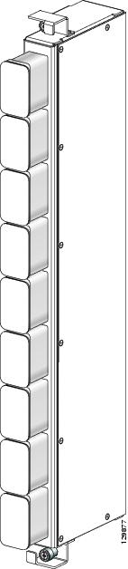
This section describes how to install an optical interface module (OIM) in the FCC. The OIM provides wiring connectivity between the SFCs and other chassis in your multishelf system. For more detailed information on the OIM, see Cisco CRS Carrier Routing System Multishelf System Description.
This figure shows an OIM.
Prerequisites
Before performing this task, you must first open the rear (OIM) side cosmetic doors (if installed) and remove the OIM impedance carrier (if necessary), see the Removing an OIM Impedance Carrier. An OIM can be installed in any of the slots OIM0 to OIM11 (upper card cage) and OIM12 to OIM23 (lower card cage).
Required Tools and Equipment
You need the following tools and part to perform this task:
- ESD-preventive wrist strap
- 6-in. long number 1 Phillips screwdriver
- OIM (Cisco product number CRS-FCC-OIM-1S=)
Steps
To install an OIM, perform the following steps:
1. Attach the ESD-preventive wrist strap to your wrist and connect its leash to an ESD connection socket on the rear (OIM) side of the chassis or to a bare metal surface on the chassis.
2. Remove the OIM from its packaging.
3. Remove all dust caps from the high-density backplane mounted (HBMT) connectors (the connectors that mate with the SFC in the chassis), and set them aside.
4. While facing the back of the chassis, determine the slots in which you will be installing the SFCs. Slide the OIM into place in back of the slot.
5. Use the screwdriver to turn the two captive screws (two at the top and two at the bottom) on the flanges of the OIM clockwise to seat the module firmly in place.
DETAILED STEPS
| Step 1 | Attach the ESD-preventive wrist strap to your wrist and connect its leash to an ESD connection socket on the rear (OIM) side of the chassis or to a bare metal surface on the chassis. | ||
| Step 2 | Remove the OIM from its packaging. | ||
| Step 3 | Remove all dust caps from the high-density backplane mounted (HBMT) connectors (the connectors that mate with the SFC in the chassis), and set them aside. | ||
| Step 4 |
While facing the back of the chassis, determine the slots in which you will be installing the SFCs. Slide the OIM into place in back of the slot.
| ||
| Step 5 |
Use the screwdriver to turn the two captive screws (two at the top and two at the bottom) on the flanges of the OIM clockwise to seat the module firmly in place.
|
What to Do Next
After performing this task, you may install an SFC (see the Installing an SFC).
Removing an OIM
This section describes how to remove an optical interface module (OIM) from the FCC. The OIM provides wiring connectivity between the SFCs and other chassis in your multishelf system. For more detailed information on the OIM, see Cisco CRS Carrier Routing System Multishelf System Description.
Prerequisites
Before performing this task, you must first open the rear (OIM) side cosmetic doors (if installed), disconnect any cables connected to the OIM (see Cisco CRS Carrier Routing System Multishelf System Interconnection and Cabling Guide ), and put dust caps on all the OIM connectors.
Required Tools and Equipment
You need the following tools to perform this task:
- ESD-preventive wrist strap
- 6-in. long number 1 Phillips screwdriver
Steps
To remove an OIM, perform the following steps:
1. Attach the ESD-preventive wrist strap to your wrist and connect its leash to an ESD connection socket on the rear (OIM) side of the chassis or to a bare metal surface on the chassis.
2. If there is an SFC mated to the OIM you are removing, partially eject the SFC from its slot. See Step 2 through Step 4 in the Removing an SFC. You do not have to fully remove the SFC from the slot.
3. While facing the rear (OIM) side of the chassis, use the screwdriver to turn the two captive screws on the flanges of the OIM counterclockwise to loosen the module.
4. Remove the OIM and set it carefully aside.
5. If you are storing the OIM, you should replace the dust caps on all connectors, including the HBMT connectors.
DETAILED STEPS
| Step 1 | Attach the ESD-preventive wrist strap to your wrist and connect its leash to an ESD connection socket on the rear (OIM) side of the chassis or to a bare metal surface on the chassis. | ||
| Step 2 | If there is an SFC mated to the OIM you are removing, partially eject the SFC from its slot. See Step 2 through Step 4 in the Removing an SFC. You do not have to fully remove the SFC from the slot. | ||
| Step 3 | While facing the rear (OIM) side of the chassis, use the screwdriver to turn the two captive screws on the flanges of the OIM counterclockwise to loosen the module. | ||
| Step 4 |
Remove the OIM and set it carefully aside.
| ||
| Step 5 | If you are storing the OIM, you should replace the dust caps on all connectors, including the HBMT connectors. |
What to Do Next
After performing this task, you may close the rear (OIM) side cosmetic doors (if installed). For more information, see the “Installing the Rear (OIM) Side Cosmetic Components” section on page 5-21 .
Installing an OIM LED Module
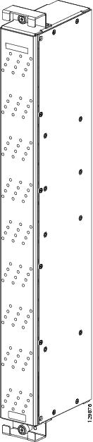
This section describes how to install an OIM LED module in the FCC. The OIM LED module provides connectivity information on how the cards in your fiber chassis are functioning in your multishelf system. For more detailed information on the OIM LED module, see Cisco CRS Carrier Routing System Multishelf System Description.
Prerequisites
Before performing this task, you must first open the rear (OIM) side cosmetic doors (if installed). An OIM LED module can be installed only in an LM0 (upper card cage) or LM1 (lower card cage) slot.
Required Tools and Equipment
You need the following tools and part to perform this task:
- ESD-preventive wrist strap
- 6-in. long number 1 Phillips screwdriver
- OIM LED module (Cisco product number CRS-FCC-LED=)
Steps
To install an OIM LED module, use perform the following steps:
1. Attach the ESD-preventive wrist strap to your wrist and connect its leash to an ESD connection socket on the rear (OIM) side of the chassis or to a bare metal surface on the chassis.
2. Remove the OIM LED module from its packaging.
3. While facing the rear (OIM) side of the chassis, firmly press the OIM LED module into place in back of the slots on the far left side of the chassis until the LED module locks into place.
4. Use the screwdriver to turn the two captive screws (one on the top and one on the bottom) on the flanges of the OIM LED module clockwise to seat the module firmly in place.
DETAILED STEPS
| Step 1 | Attach the ESD-preventive wrist strap to your wrist and connect its leash to an ESD connection socket on the rear (OIM) side of the chassis or to a bare metal surface on the chassis. |
| Step 2 | Remove the OIM LED module from its packaging. |
| Step 3 | While facing the rear (OIM) side of the chassis, firmly press the OIM LED module into place in back of the slots on the far left side of the chassis until the LED module locks into place. |
| Step 4 | Use the screwdriver to turn the two captive screws (one on the top and one on the bottom) on the flanges of the OIM LED module clockwise to seat the module firmly in place. |
What to Do Next
After performing this task, you may close the doors on the rear (OIM) side of the chassis (if installed). For more information, see the “Installing the Rear (OIM) Side Cosmetic Components” section on page 5-21 .
Removing an OIM LED Module
This section describes how to remove an OIM LED module from the FCC. The OIM LED module provides connectivity information on how the cards in your fiber chassis are functioning in your multishelf system. For more detailed information on the OIM LED modules, see Cisco CRS Carrier Routing System Multishelf System Description.
Prerequisites
Before performing this task, you must first open the rear (OIM) side cosmetic doors (if installed).
Required Tools and Equipment
You need the following tools to perform this task:
- ESD-preventive wrist strap
- 6-in. long number 1 Phillips screwdriver
Steps
To remove an OIM LED module, perform the following steps:
1. Attach the ESD-preventive wrist strap to your wrist and connect its leash to an ESD connection socket on the rear (OIM) side of the chassis or to a bare metal surface on the chassis.
2. While facing the rear (OIM) side of the chassis, use the screwdriver to turn the two captive screws on the flanges of the OIM LED module counterclockwise to loosen the module.
3. Holding the top and bottom flanges of the module, tug firmly to unseat the module from the chassis.
4. Remove the OIM LED module and set it carefully aside.
DETAILED STEPS
| Step 1 | Attach the ESD-preventive wrist strap to your wrist and connect its leash to an ESD connection socket on the rear (OIM) side of the chassis or to a bare metal surface on the chassis. | ||
| Step 2 | While facing the rear (OIM) side of the chassis, use the screwdriver to turn the two captive screws on the flanges of the OIM LED module counterclockwise to loosen the module. | ||
| Step 3 |
Holding the top and bottom flanges of the module, tug firmly to unseat the module from the chassis.
| ||
| Step 4 | Remove the OIM LED module and set it carefully aside. |
What to Do Next
After performing this task, you may install a new OIM LED module. For more information, see the Installing an OIM LED Module.
Installing an SFC
This section describes how to install a switch fabric card (SFC) in the FCC. For more detailed information on the different types of switch fabric cards available and details on the cards themselves, see Cisco CRS Carrier Routing System Multishelf System Description.
 Warning | Class 1M laser radiation when open. Do not view directly with optical instruments. Statement 281 |
Warning | For diverging beams, viewing the laser output with certain optical instruments within a distance of 100 mm may pose an eye hazard. For collimated beams, viewing the laser output with certain optical instruments designed for use at a distance may pose an eye hazard. Statement 282 |
Warning | Laser radiation. Do not view directly with optical instruments. Class 1M laser product. Statement 283 |
This figure shows the front view of a CRS-FCC-SFC switch fabric card that is installed in a 40G multishelf system. The CRS-FCC-SFC-140 and CRS-FCC-SFC-400 are similar.

|
1 |
Status LED |
3 |
Handle |
|
2 |
Alphanumeric display |
|
|
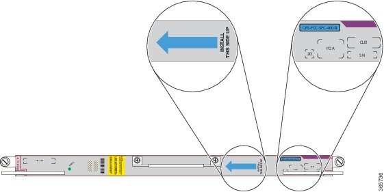
This figure shows the front view of a CRS-FCC-SFC-400-B switch fabric card that is used in CRS-X systems.
Prerequisites
Before performing this task, you must first open the front (SFC) side cosmetic doors (if installed). You must already have an OIM installed in your chassis in the slot corresponding to where you plan to install the SFC before you install the SFC (for example, if you are planning on installing the SFC in slot 0, you must have an OIM installed in slot 0 on the rear of the chassis), and you must remove any impedance carrier or slot cover from the slot in which you are installing the SFC. See the Installing an OIM, the Removing a Slot Cover, and the Removing an Impedance Carrier. If you are replacing an SFC, you must remove the currently installed SFC from the slot and set it carefully aside. See the Removing an SFC for more information.
An SFC can be installed in any of the slots SFC0 to SFC11 (upper card cage) and SFC12 to SFC23 (lower card cage).
Note | Remove only one impedance carrier or SFC and install one SFC at a time. Be sure to verify that each SFC is fully installed and secured before installing another card. Allow at least 15 seconds for the router to complete the preceding tasks before removing or installing another card. |
Caution | Use the slide-assistance arm to slide cards from the card carrier. DO NOT LIFT CARDS BY THE SLIDE-ASSISTANCE ARM! Rotate cards onto their vertical axes, then lift them from the bottom, using the slide-assistance arm only as an aid for balance. |
Required Tools and Equipment
You need the following tools and part to perform this task:
- ESD-preventive wrist strap
- 6-in. long number 1 Phillips screwdriver
-
Switch fabric card
- 40 G SFC (Cisco product number CRS-FCC-SFC), or
- 140 G SFC (Cisco product number CRS-FCC-SFC-140), or
- 400 G SFC (Cisco product number CRS-FCC-SFC-400) or (Cisco product number CRS-FCC-SFC-400-B)
Steps
To install an SFC, perform the following steps:
1. Attach the ESD-preventive wrist strap to your wrist and connect its leash to an ESD connection socket on the front of the chassis or to a bare metal surface on the chassis.
2. Choose a mated SFC slot with an OIM.
3. Remove the SFC you are installing from its antistatic packaging.
4. Use the screwdriver to unscrew and remove the sheetmetal cover over the HBMT connectors on the rear of the SFC, and set it aside.
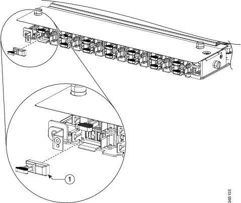
5. Remove the caps from the HBMT connectors on the back of the card, and set them carefully aside.
6. Visually inspect the connector on the card before you insert it into the chassis. Do not attempt to install a card with a damaged or dirty connector, as this action may damage the backplane connector or OIM.
7. Position the card for insertion into the card cage slot. Avoid touching the card circuitry or any connectors.
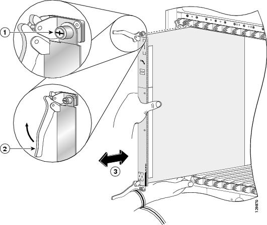
8. Grasp the slide assistance arm with one hand and place your other hand under the carrier to support and guide it into the correct slot. DO NOT LIFT CARDS BY THE SLIDE-ASSISTANCE ARM; lift them from the bottom, using the slide-assistance arm only as an aid for balance. See the figure below.
9. Slide the card halfway into the slot.
10. Pivot both card ejector levers so the openings on the card ejector cams at the top and bottom of the card pass over the tabs on each side of the card cage slot.
11. Continue sliding the card into the card cage slot until the openings on the card ejector cams engage the tabs on each side of the card cage slot.
12. To seat the card in the backplane connector, grasp both card ejector levers and pivot them inward toward the handle in the card carrier until they are flush against the front edge of the card carrier.
13. Use the screwdriver to turn the two captive screws on the front panel of the SFC clockwise to seat the card firmly in the slot.
DETAILED STEPS
| Step 1 | Attach the ESD-preventive wrist strap to your wrist and connect its leash to an ESD connection socket on the front of the chassis or to a bare metal surface on the chassis. | ||||||||||
| Step 2 | Choose a mated SFC slot with an OIM. | ||||||||||
| Step 3 | Remove the SFC you are installing from its antistatic packaging. | ||||||||||
| Step 4 | Use the screwdriver to unscrew and remove the sheetmetal cover over the HBMT connectors on the rear of the SFC, and set it aside. | ||||||||||
| Step 5 | Remove the caps from the HBMT connectors on the back of the card,
and set them carefully aside.
| ||||||||||
| Step 6 | Visually inspect the connector on the card before you insert it into the chassis. Do not attempt to install a card with a damaged or dirty connector, as this action may damage the backplane connector or OIM. | ||||||||||
| Step 7 | Position the card for insertion into the card cage slot. Avoid
touching the card circuitry or any connectors.
| ||||||||||
| Step 8 | Grasp the slide assistance arm with one hand and place your other hand under the carrier to support and guide it into the correct slot. DO NOT LIFT CARDS BY THE SLIDE-ASSISTANCE ARM; lift them from the bottom, using the slide-assistance arm only as an aid for balance. See the figure below.
| ||||||||||
| Step 9 | Slide the card halfway into the slot. | ||||||||||
| Step 10 | Pivot both card ejector levers so the openings on the card
ejector cams at the top and bottom of the card pass over the tabs on each side
of the card cage slot.
| ||||||||||
| Step 11 | Continue sliding the card into the card cage slot until the
openings on the card ejector cams engage the tabs on each side of the card cage
slot.
| ||||||||||
| Step 12 | To seat the card in the backplane connector, grasp both card ejector levers and pivot them inward toward the handle in the card carrier until they are flush against the front edge of the card carrier. | ||||||||||
| Step 13 | Use the screwdriver to turn the two captive screws on the front panel of the SFC clockwise to seat the card firmly in the slot. |
What to Do Next
After performing this task, you may close the doors on the front (SFC) side of the chassis (if installed). For more information, see the How to Install and Remove Cards and Associated Components.
Removing an SFC
This section describes how to remove a switch fabric card (SFC) from the FCC. For more detailed information on the different types of switch fabric cards available and details on the cards themselves, see the Cisco CRS Carrier Routing System Multishelf System Description.
Caution | Class 1M laser radiation when open. Do not view directly with optical instruments. Statement 281 |
Warning | For diverging beams, viewing the laser output with certain optical instruments within a distance of 100 mm may pose an eye hazard. For collimated beams, viewing the laser output with certain optical instruments designed for use at a distance may pose an eye hazard. Statement 282 |
Warning | Laser radiation. Do not view directly with optical instruments. Class 1M laser product. Statement 283 |
This figure shows the front view of a CRS-FCC-SFC switch fabric card that is installed in a 40G multishelf system. The CRS-FCC-SFC-140 and CRS-FCC-SFC-400 are similar.
|
1 |
Status LED |
3 |
Handle |
|
2 |
Alphanumeric display |
|
|
This figure shows the front view of a CRS-FCC-SFC-400-B switch fabric card that is used for CRS-X systems.
Prerequisites
Before performing this task, you must first open the front cosmetic doors (if installed).
Caution | Use the slide-assistance arm to slide cards from the card carrier. DO NOT LIFT CARDS BY THE SLIDE-ASSISTANCE ARM! Rotate cards onto their vertical axes, then lift them from the bottom, using the slide-assistance arm only as an aid for balance. |
Required Tools and Equipment
You need the following tools to perform this task:
- ESD-preventive wrist strap
- 6-in. long number 1 Phillips screwdriver
Steps
To remove an SFC, perform the following steps:
1. Attach the ESD-preventive wrist strap to your wrist and connect its leash to an ESD connection socket on the front of the chassis or to a bare metal surface on the chassis.
2. Identify the card to be removed in the card cage. Use the screwdriver to turn the two captive screws on the front panel of the card counterclockwise to loosen the card from the slot. See this figure.
3. Grasp the two card ejector levers and simultaneously pivot both ejector levers about 90 degrees away from the front edge of the card carrier to unseat the card from the backplane connector.
4. Grasp the slide-assistance arm and gently pull the SFC halfway from the slot.
5. Move one hand under the SFC to guide it. Avoid touching the SFC printed circuit board, components, and any connector pins. DO NOT LIFT CARDS BY THE SLIDE-ASSISTANCE ARM; lift them from the bottom, using the slide-assistance arm only as an aid for balance.
6. Slide the card completely from the slot.
7. Replace the caps on the HBMT connectors on the back of the card.
8. Place the card directly into an antistatic sack or other ESD-preventive container. If you plan to return the defective card to the factory, repackage it in a Cisco SFC shipping container.
DETAILED STEPS
| Step 1 | Attach the ESD-preventive wrist strap to your wrist and connect its leash to an ESD connection socket on the front of the chassis or to a bare metal surface on the chassis. | ||||||||
| Step 2 | Identify the card to be removed in the card cage. Use the screwdriver to turn the two captive screws on the front panel of the card counterclockwise to loosen the card from the slot. See this figure.
| ||||||||
| Step 3 |
Grasp the two card ejector levers and simultaneously pivot both ejector levers about 90 degrees away from the front edge of the card carrier to unseat the card from the backplane connector.
| ||||||||
| Step 4 | Grasp the slide-assistance arm and gently pull the SFC halfway from the slot. | ||||||||
| Step 5 | Move one hand under the SFC to guide it. Avoid touching the SFC printed circuit board, components, and any connector pins. DO NOT LIFT CARDS BY THE SLIDE-ASSISTANCE ARM; lift them from the bottom, using the slide-assistance arm only as an aid for balance. | ||||||||
| Step 6 |
Slide the card completely from the slot.
| ||||||||
| Step 7 | Replace the caps on the HBMT connectors on the back of the card. | ||||||||
| Step 8 | Place the card directly into an antistatic sack or other ESD-preventive container. If you plan to return the defective card to the factory, repackage it in a Cisco SFC shipping container. |
What to Do Next
After performing this task, you may install a new replacement SFC, See the Installing an SFC.
Verifying the Installation of an SFC
This section describes how to verify that a switch fabric card (SFC) has been properly installed. The figure below shows the front panel on the 40 G CRS-FCC-SFC switch fabric card. The front panel on the CRS-FCC-SFC-140 and CRS-FCC-SFC-400 are similar.

The figure below shows the front panel on the 400 G CRS-FCC-SFC-400-B switch fabric card. The blue arrow indicates the direction in which the PLIM has to be installed. The product number is indicated inside a blue bubble.
Understanding the Alphanumeric LEDs
At one end of the faceplate, near an ejector lever, an SFC has two four-digit alphanumeric LED displays that show a sequence of messages indicating the state of the card. In normal operation, the LED module should display IOS-XR .
Note | It is normal for some displayed messages to appear too briefly in the LED display to be read. |
Troubleshooting the SFC
If the installed or replaced SFC fails to operate or power up on installation:
- Make sure that the card is seated firmly in the FCC slot. One easy way to verify physical installation is to see whether the front faceplate of the SFC is even with the fronts of the other cards installed in the card cage.
- Check whether the ejector levers are latched and that the captive screws are fastened properly. If you are uncertain, unlatch the levers, loosen the screws, and attempt to reseat the SFC.
- Examine the FCC alarm module to see if there are any active alarm conditions. (See the section on the alarm module in Cisco CRS Carrier Routing System Multishelf System Description .)
- Examine the FCC power shelves to see whether the chassis, as a whole, is receiving power.
Use the Status LEDs, located on the SFC faceplate, to verify the correct installation of the SFC:
- When the SFC is properly installed, the Status LED turns green. If this LED is off, verify that the SFC is installed correctly.
- If a failure occurs during the board boot sequence, the two four-digit alphanumeric LED displays indicate the current boot phase to assist you in debugging the board failure.
Installing an SCGE Card
This section describes how to install a shelf controller Gigabit Ethernet (SCGE) card in the FCC. For more detailed information on the SCGE card, see Cisco CRS Carrier Routing System Multishelf System Description.
Each card cage in the FCC has a slot for an SCGE card (see following figure, CRS-FCC-SC-22GE SCGE Card—Front Panel View). Each populated card cage requires one SCGE card.
Warning | Class 1 Laser Product. Statement 113 |
Warning | Because invisible radiation may be emitted from the aperture of the port when no fiber cable is connected, avoid exposure to radiation and do not stare into open apertures. Statement 125 |
Caution | Always use an electrostatic discharge (ESD) wrist strap when handling SCGE cards. |
This figure shows the front panel of the CRS-FCC-SC-22GE SCGE card in a horizontal view.
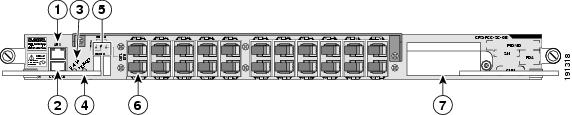
|
1 |
RJ-45 auxiliary (AUX) port |
5 |
Alphanumeric LEDs |
|
2 |
RJ-45 console port |
6 |
Gigabit ethernet interface |
|
3 |
Status LED |
7 |
PCMCIA card slots |
|
4 |
Primary LED |
|
|
This figure shows the front panel of the CRS-FCC-SC-22GE-B SCGE card in a horizontal view.
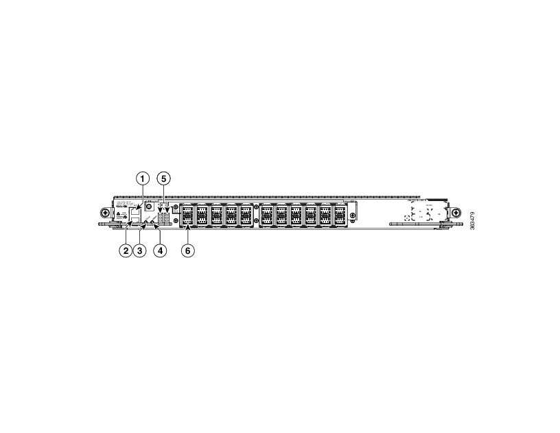
|
1 |
RJ-45 auxiliary (AUX) port |
4 |
Primary LED |
|
2 |
RJ-45 console port |
5 |
Alphanumeric LEDs |
|
3 |
Status LED |
6 |
Gigabit ethernet interface |
Prerequisites
Before performing this task, you must first open the front cosmetic doors (if installed). An SCGE card can be installed only in an SCGE0 (upper card cage) or SCGE1 (lower card cage) slot.
Caution | You can use the card cable management bracket to slide cards from the card carrier. DO NOT LIFT CARDS BY THE CABLE MANAGEMENT BRACKET! Rotate cards onto their vertical axes, then lift them from the bottom, using the bracket only as an aid for balance. |
Required Tools and Equipment
You need the following tools and part to perform this task:
- ESD-preventive wrist strap
- 6-in. long number 1 Phillips screwdriver
- 22-port SCGE card (Cisco product number CRS-FCC-SC-22GE or CRS-FCC-SC-22GE-B)
Steps
To install an SCGE card, see the following figure and perform the following steps:
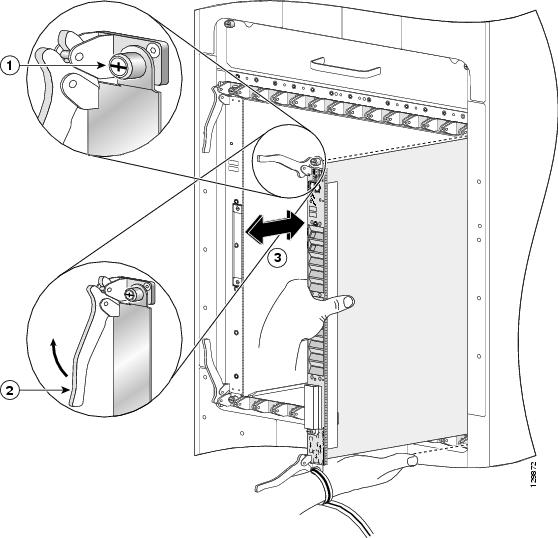
|
1 |
Captive screw |
3 |
Direction of installation or removal |
|
2 |
Ejector lever |
|
|
1. Attach the ESD-preventive wrist strap to your wrist and connect its leash to an ESD connection socket on the front of the chassis or to a bare metal surface on the chassis.
2. Remove the SCGE slot impedance carrier or the SCGE card you are replacing from the designated slot, and set it aside. (See the Removing an Impedance Carrier or the Removing an SFC.)
3. Remove the SCGE card you are installing from its antistatic packaging.
4. Visually inspect the connector on the card before you insert it into the chassis. Do not attempt to install a card with a damaged connector, as this action may damage the backplane connector or OIM.
5. Grasp the card cable management bracket with one hand and place your other hand under the card to support and guide it into the correct slot. DO NOT LIFT CARDS BY THE CABLE MANAGEMENT BRACKET; lift them from the bottom, using the cable management bracket only as an aid for balance.
6. Slide the card halfway into the slot. Avoid touching the card circuitry and any connectors.
7. Pivot both card ejector levers so the openings on the card ejector cams at the top and bottom of the card pass over the tabs on each side of the card cage slot.
8. Continue sliding the card into the card cage slot until the openings on the card ejector cams engage the tabs on each side of the card cage slot.
9. To seat the card in the backplane connector, grasp both card ejector levers and pivot them inward toward the handle in the card carrier until they are flush against the front edge of the card carrier.
10. Use the screwdriver to turn the two captive screws on the front panel of the SCGE card clockwise to seat the card firmly in the slot.
DETAILED STEPS
| Step 1 | Attach the ESD-preventive wrist strap to your wrist and connect its leash to an ESD connection socket on the front of the chassis or to a bare metal surface on the chassis. | ||||
| Step 2 | Remove the SCGE slot impedance carrier or the SCGE card you are replacing from the designated slot, and set it aside. (See the Removing an Impedance Carrier or the Removing an SFC.)
| ||||
| Step 3 | Remove the SCGE card you are installing from its antistatic packaging. | ||||
| Step 4 |
Visually inspect the connector on the card before you insert it into the chassis. Do not attempt to install a card with a damaged connector, as this action may damage the backplane connector or OIM.
| ||||
| Step 5 |
Grasp the card cable management bracket with one hand and place your other hand under the card to support and guide it into the correct slot. DO NOT LIFT CARDS BY THE CABLE MANAGEMENT BRACKET; lift them from the bottom, using the cable management bracket only as an aid for balance.
| ||||
| Step 6 | Slide the card halfway into the slot. Avoid touching the card circuitry and any connectors. | ||||
| Step 7 |
Pivot both card ejector levers so the openings on the card ejector cams at the top and bottom of the card pass over the tabs on each side of the card cage slot.
| ||||
| Step 8 |
Continue sliding the card into the card cage slot until the openings on the card ejector cams engage the tabs on each side of the card cage slot.
| ||||
| Step 9 | To seat the card in the backplane connector, grasp both card ejector levers and pivot them inward toward the handle in the card carrier until they are flush against the front edge of the card carrier. | ||||
| Step 10 | Use the screwdriver to turn the two captive screws on the front panel of the SCGE card clockwise to seat the card firmly in the slot. |
What to Do Next
After performing this task, you may close the doors on the front (SFC) side of the chassis (if installed). For more information, see the How to Install and Remove Cards and Associated Components.
Removing an SCGE Card
This section describes how to remove a shelf controller Gigabit Ethernet (SCGE) from the FCC. For more detailed information on the SCGE card, see Cisco CRS Carrier Routing System Multishelf System Description.
Each card cage in the FCC has a slot for an SCGE card. Each populated card cage requires an SCGE card.
Warning | Class 1 Laser Product. Statement 113 |
Warning | Because invisible radiation may be emitted from the aperture of the port when no fiber cable is connected, avoid exposure to radiation and do not stare into open apertures. Statement 125 |
Caution | Always use an electrostatic discharge (ESD) wrist strap when handling SCGE cards. |
This figure shows the front panel of the CRS-FCC-SC-22GE SCGE card in a horizontal view.
|
1 |
RJ-45 auxiliary (AUX) port |
5 |
Alphanumeric LEDs |
|
2 |
RJ-45 console port |
6 |
Gigabit ethernet interface |
|
3 |
Status LED |
7 |
PCMCIA card slots |
|
4 |
Primary LED |
|
|
This figure shows the front panel of the CRS-FCC-SC-22GE-B SCGE card in a horizontal view.
|
1 |
RJ-45 auxiliary (AUX) port |
4 |
Primary LED |
|
2 |
RJ-45 console port |
5 |
Alphanumeric LEDs |
|
3 |
Status LED |
6 |
Gigabit ethernet interface |
Prerequisites
Before performing this task, you must first open the front cosmetic doors (if installed).
Caution | You can use the card cable management bracket to slide cards from the card carrier. DO NOT LIFT CARDS BY THE CABLE MANAGEMENT BRACKET! Rotate cards onto their vertical axes, then lift them from the bottom, using the bracket only as an aid for balance. |
Required Tools and Equipment
You need the following tools to perform this task:
- ESD-preventive wrist strap
- 6-in. long number 1 Phillips screwdriver
Steps
To remove an SCGE card, see Figure 1 and perform the following steps:
1. Attach the ESD-preventive wrist strap to your wrist and connect its leash to an ESD connection socket on the front of the chassis or to a bare metal surface on the chassis.
2. Identify the card to be removed in the card cage. Use the screwdriver to turn the two captive screws on the front panel of the SFC counterclockwise to loosen the card from the slot. See Figure 4-31 .
3. Grasp the two card ejector levers and simultaneously pivot both ejector levers about 90 degrees away from the front edge of the card carrier to unseat the card from the backplane connector.
4. Grasp the card cable management bracket and gently pull the SCGE card halfway from the slot.
5. Move one hand under the card to guide it. Avoid touching the card’s printed circuit board, components, and any connector pins. DO NOT LIFT CARDS BY THE CARD CABLE MANAGEMENT BRACKET; lift them from the bottom, using the cable management bracket only as an aid for balance.
6. Slide the card completely from the slot.
7. Place the card directly into an antistatic sack or other ESD-preventive container. If you plan to return the defective card to the factory, repackage it in a Cisco SCGE card shipping container.
DETAILED STEPS
| Step 1 | Attach the ESD-preventive wrist strap to your wrist and connect its leash to an ESD connection socket on the front of the chassis or to a bare metal surface on the chassis. | ||||||||
| Step 2 |
Identify the card to be removed in the card cage.
Use the screwdriver to turn the two captive screws on the front panel of the SFC counterclockwise to loosen the card from the slot. See
Figure 4-31
.
| ||||||||
| Step 3 |
Grasp the two card ejector levers and simultaneously pivot both ejector levers about 90 degrees away from the front edge of the card carrier to unseat the card from the backplane connector.
| ||||||||
| Step 4 | Grasp the card cable management bracket and gently pull the SCGE card halfway from the slot. | ||||||||
| Step 5 | Move one hand under the card to guide it. Avoid touching the card’s printed circuit board, components, and any connector pins. DO NOT LIFT CARDS BY THE CARD CABLE MANAGEMENT BRACKET; lift them from the bottom, using the cable management bracket only as an aid for balance. | ||||||||
| Step 6 |
Slide the card completely from the slot.
| ||||||||
| Step 7 | Place the card directly into an antistatic sack or other ESD-preventive container. If you plan to return the defective card to the factory, repackage it in a Cisco SCGE card shipping container. |
What to Do Next
After performing this task, you may close the doors on the front (SFC) side of the chassis (if installed). For more information, see the How to Install and Remove Cards and Associated Components.
Verifying the Installation of an SCGE Card
This section describes how to verify that the SCGE card has been properly installed.
This figure shows the front panel of the CRS-FCC-SC-22GE SCGE card in a horizontal view.
|
1 |
RJ-45 auxiliary (AUX) port |
5 |
Alphanumeric LEDs |
|
2 |
RJ-45 console port |
6 |
Gigabit ethernet interface |
|
3 |
Status LED |
7 |
PCMCIA card slots |
|
4 |
Primary LED |
|
|
This figure shows the front panel of the CRS-FCC-SC-22GE-B SCGE card in a horizontal view.
|
1 |
RJ-45 auxiliary (AUX) port |
4 |
Primary LED |
|
2 |
RJ-45 console port |
5 |
Alphanumeric LEDs |
|
3 |
Status LED |
6 |
Gigabit ethernet interface |
Understanding the Alphanumeric LEDs
At one end of the faceplate, near an ejector lever, an SCGE card has two four-digit alphanumeric LED displays that show a sequence of messages indicating the state of the card.
Note | It is normal for some displayed messages to appear too briefly in the LED display to be read. |
Troubleshooting the SCGE Card
If the installed or replaced SCGE card fails to operate or power up on installation:
- Make sure that the card is seated firmly into the FCC slot. One easy way to verify physical installation is to see whether the front faceplate of the SCGE card is even with the fronts of the other cards installed in the card cage.
- Check whether the ejector levers are latched and that the captive screws are fastened properly. If you are uncertain, unlatch the levers, loosen the screws, and attempt to reseat the SCGE card.
- Examine the alarm module to see if there are any active alarm conditions. (See a section on the alarm module in Cisco CRS Carrier Routing System Multishelf System Description.)
- Examine the power shelves to see whether the chassis, as a whole, is receiving power.
Use the Status LEDs, located on the SCGE card faceplate, to verify the correct installation of the card:
- When the card is properly installed, the Status LED turns green. If this LED is off, verify that the card is installed correctly.
- When the Status LED is blinking yellow, a problem exists on the board.
- When the Status LED is off, the board status is unknown. Verify that there is power to the board by looking at the indicators on the power shelf.
- If there is a failure during the board boot sequence, the two four-digit alphanumeric display indicates the current boot phase to assist you in debugging the board failure.
Installing a PCMCIA Card Into an SCGE Card
This section describes how to install a PCMCIA card in the PCMCIA slot of a 22-port SCGE card (CRS-FCC-SC-22GE only) card. For more detailed information on the SCGE PCMCIA card, see Cisco CRS Carrier Routing System Multishelf System Description.
The CRS-FCC-SC-22GE SCGE card provides two PCMCIA flash slots, each of which provides up to 1 GB of flash storage. One of the PCMCIA flash subsystems is accessible externally and removable and allows you to transfer images and configurations by plugging in a PCMCIA flash card. The other subsystem is fixed to the SCGE card, not removable, and is for permanent storage of configurations and images. This figure shows the location of the PCMCIA door in the CRS-FCC-SC-22GE SCGE card faceplate.
|
1 |
RJ-45 auxiliary (AUX) port |
5 |
Alphanumeric LEDs |
|
2 |
RJ-45 console port |
6 |
Gigabit ethernet interface |
|
3 |
Status LED |
7 |
PCMCIA card slots |
|
4 |
Primary LED |
|
|
Prerequisites
If you are replacing a PCMCIA card, see the Removing a PCMCIA Card From the SCGE Card to remove the PCMCIA card from the CRS-FCC-SC-22GE SCGE PCMCIA card slot.
Before performing this task open the cosmetic doors (if installed).
Required Tools and Equipment
You need the following tools and part to perform this task:
- ESD-preventive strap
- 1/4 in. x 6 in. long slotted screwdriver
- PCMCIA card
Steps
To install a PCMCIA card into a CRS-FCC-SC-22GE SCGE card PCMCIA slot, perform the following steps:
1. Attach the ESD-preventive wrist strap to your wrist and connect its leash to an ESD connection socket on the front of the chassis or to a bare metal surface on the chassis.
2. Using the screwdriver, loosen the captive screw at the bottom of the PCMCIA slot door on the faceplate of the card.
3. While lifting the hinged PCMCIA slot door up, carefully insert the new PCMCIA card into the left slot of the PCMCIA card cage. When the card is fully inserted, the release button pops up. (If the button fails to pop up, you may not have the card in right side up; turn the card over and try again.)
4. Close the door to keep dust out, and tighten the captive screw with the screwdriver.
DETAILED STEPS
| Step 1 | Attach the ESD-preventive wrist strap to your wrist and connect its leash to an ESD connection socket on the front of the chassis or to a bare metal surface on the chassis. |
| Step 2 | Using the screwdriver, loosen the captive screw at the bottom of the PCMCIA slot door on the faceplate of the card. |
| Step 3 | While lifting the hinged PCMCIA slot door up, carefully insert the new PCMCIA card into the left slot of the PCMCIA card cage. When the card is fully inserted, the release button pops up. (If the button fails to pop up, you may not have the card in right side up; turn the card over and try again.) |
| Step 4 | Close the door to keep dust out, and tighten the captive screw with the screwdriver. |
What to Do Next
After performing this task, you may close the doors on the front (SFC) side of the chassis (if installed). For more information, see the How to Install and Remove Cards and Associated Components.
Removing a PCMCIA Card From the SCGE Card
This section describes how to remove a PCMCIA card from the PCMCIA slot of a CRS-FCC-SC-22GE SCGE card. For more detailed information on the CRS-FCC-SC-22GE PCMCIA card, see Cisco CRS Carrier Routing System Multishelf System Description.
The CRS-FCC-SC-22GE card provides two PCMCIA flash slots, each of which provides up to 1 GB of flash storage. One of the PCMCIA flash subsystems is accessible externally and removable and allows you to transfer images and configurations by plugging in a PCMCIA flash card. The other subsystem is fixed to the SCGE card, not removable, and is for permanent storage of configurations and images. This figure shows the location of the PCMCIA door in the CRS-FCC-SC-22GE card faceplate.
|
1 |
RJ-45 auxiliary (AUX) port |
5 |
Alphanumeric LEDs |
|
2 |
RJ-45 console port |
6 |
Gigabit ethernet interface |
|
3 |
Status LED |
7 |
PCMCIA card slots |
|
4 |
Primary LED |
|
|
Prerequisites
Before performing this task, open the front (SFC) side cosmetic doors (if installed).
Required Tools and Equipment
You need the following tools to perform this task:
- ESD-preventive strap
- 1/4 in. x 6 in. long slotted screwdriver
Steps
To remove a PCMCIA card from a CRS-FCC-SC-22GE card PCMCIA slot, perform the following steps:
1. Attach the ESD-preventive wrist strap to your wrist and connect its leash to an ESD connection socket on the front of the chassis or to a bare metal surface on the chassis.
2. Using the screwdriver, loosen the captive screw at the bottom of the PCMCIA slot door on the faceplate of the card.
3. While lifting the hinged PCMCIA slot door up, press the release button on the card slot to disengage the card from the card, and then carefully pull out the far left removable PCMCIA flash card.
4. Place the removed PCMCIA card on an antistatic mat, or immediately place it in an antistatic bag if you plan to return it to the factory.
5. If the PCMCIA card slot is to remain empty, close the door to keep dust out, and tighten the captive screw with the screwdriver. Otherwise, install your new PCMCIA card.
DETAILED STEPS
| Step 1 | Attach the ESD-preventive wrist strap to your wrist and connect its leash to an ESD connection socket on the front of the chassis or to a bare metal surface on the chassis. |
| Step 2 | Using the screwdriver, loosen the captive screw at the bottom of the PCMCIA slot door on the faceplate of the card. |
| Step 3 | While lifting the hinged PCMCIA slot door up, press the release button on the card slot to disengage the card from the card, and then carefully pull out the far left removable PCMCIA flash card. |
| Step 4 | Place the removed PCMCIA card on an antistatic mat, or immediately place it in an antistatic bag if you plan to return it to the factory. |
| Step 5 | If the PCMCIA card slot is to remain empty, close the door to keep dust out, and tighten the captive screw with the screwdriver. Otherwise, install your new PCMCIA card. |
What to Do Next
If you intend to install a new PCMCIA card, see the Installing a PCMCIA Card Into an SCGE Card.
 Feedback