- Overview of Cisco IoT Field Network Director
- Installing Cisco IoT FND
- Generating and Installing Certificates
- Managing User Access
- Managing System Settings
- Managing Devices
- Managing Firmware Upgrades
- Managing Tunnel Provisioning
- Monitoring System Activity
- Managing High Availability Installations
- Troubleshooting IoT FND
- Managing Routers
- Working with Router Views
- Migrating Router Operating Systems
- Creating Work Orders
- Refreshing the Router Mesh Key
- Managing Embedded Access Points on Cisco C819 and Cisco IR829 ISRs
- Using Router Filters
- Displaying Router Configuration Groups
- Displaying Router Firmware Groups
- Displaying Router Tunnel Groups
- Managing Mesh Endpoints
- Managing Head-End Routers
- Managing Servers
- Common Device Operations
- Selecting Devices
- Customizing Device Views
- Viewing Devices in Map View
- Configuring Map Settings
- Changing the Sorting Order of Devices
- Exporting Device Information
- Pinging Devices
- Tracing Routes to Devices
- Managing Device Labels
- Removing Devices
- Displaying Detailed Device Information
- Using Filters to Control the Display of Devices
- Performing Bulk Import Actions
- Types of Device Properties
- Device Properties by Category
- Cellular Link Settings
- Cellular Link Metrics
- DA Gateway Properties
- Dual PHY WPAN Properties
- Embedded Access Point Credentials
- Embedded AP Properties
- Ethernet Link Metrics
- Guest OS Properties
- Head-End Routers > Netconf Config
- Head-End Routers > Tunnel 1 Config
- Head-End Routers > Tunnel 2 Config
- Inventory
- Mesh Link Config
- Mesh Device Health
- Mesh Link Keys
- Mesh Link Settings
- Mesh Link Metrics
- NAT44 Metrics
- PLC Mesh Info
- Raw Sockets Metrics and Sessions
- Router Battery
- Router Config
- Router Credentials
- Router DHCP Info
- Router DHCP Proxy Config
- Router Health
- Router Tunnel Config
- Router Tunnel 1 Config
- Router Tunnel 2 Config
- SCADA Metrics
- User-defined Properties
- WiFi Interface Config
- WiMAX Config
- WiMAX Link Metrics
- WiMAX Link Settings
Managing Devices
This section describes how to manage devices in IoT FND, and includes the following topics:
Use the following IoT FND pages to monitor, add and remove devices, and perform other device management tasks that do not include device configuration:
■![]() To work with FARs and MEs, use the Field Devices page (Devices > Field Devices).
To work with FARs and MEs, use the Field Devices page (Devices > Field Devices).
■![]() To work with HERs, use the Head-End Routers page (Devices > Head-End Routers).
To work with HERs, use the Head-End Routers page (Devices > Head-End Routers).
■![]() To work with database and NMS servers, use the Servers page (Devices > Servers).
To work with database and NMS servers, use the Servers page (Devices > Servers).
■![]() To configure the device properties of routers and MEs, use the Device Configuration page (Config > Device Configuration).
To configure the device properties of routers and MEs, use the Device Configuration page (Config > Device Configuration).
Managing Routers
You manage routers on the Field Devices page (Devices > Field Devices). By default, the page displays devices in Default view. This section includes the following topics:
■![]() Refreshing the Router Mesh Key
Refreshing the Router Mesh Key
■![]() Managing Embedded Access Points on Cisco C819 and Cisco IR829 ISRs
Managing Embedded Access Points on Cisco C819 and Cisco IR829 ISRs
■![]() Displaying Router Configuration Groups
Displaying Router Configuration Groups
■![]() Displaying Router Firmware Groups
Displaying Router Firmware Groups
■![]() Displaying Router Tunnel Groups
Displaying Router Tunnel Groups
Working with Router Views
Unless you select the Default to map view option in user preferences (see Setting User Preferences), the Field Devices page defaults to List view, which contains basic device properties. Select a router or group of routers in the Browse Devices pane to display tabs in the main pane that display the following router properties:
Each of these views displays different sets of device properties. For example, the Default view displays basic device properties, and the Cellular-GSM view displays device properties particular to the cellular network.
For information on how to customize router views, see Customizing Device Views.
For information about the device properties that display in each view, see Device Properties.
For information about common actions performed in these views (for example, adding labels and changing device properties), see Common Device Operations.
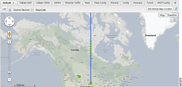
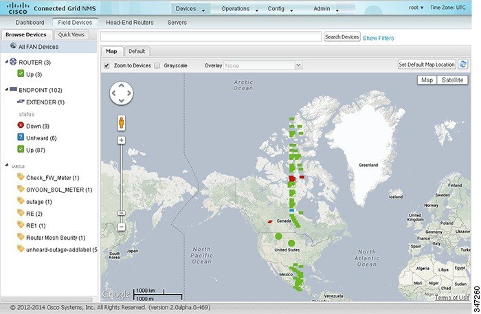
Viewing Routers in Map View
To view routers in Map view, check the Enable map check box in <user> > Preferences, and then click the Map tab in the main pane (see Setting User Preferences). You can view any RPL tree by clicking the device in Map view, and closing the information popup window. The RPL tree connection displays data traffic flow as blue or orange lines, as follows:
■![]() Orange lines indicate that the link is an uplink: data traffic flows in the up direction on the map
Orange lines indicate that the link is an uplink: data traffic flows in the up direction on the map
■![]() Blue lines indicate that the link is a downlink: data traffic flows in the down direction on the map
Blue lines indicate that the link is a downlink: data traffic flows in the down direction on the map
Figure 1 Map View: Downlink Data Flow RPL Trees
Migrating Router Operating Systems
You migrate CGR operating systems from CG-OS to IOS on the Config > Firmware Update page, using the procedure in Performing OS Migrations.
Creating Work Orders
Create work orders in IoT FND to deploy field technicians for device inspections. Field technicians use the IoT-DM client to connect to IoT FND and download the work order.
Note: The Work Orders feature works with Release 3.0 or later of Device Manager (IoT-DM) only. See “Accessing Work Authorizations” in the Cisco Connected Grid Device Manager Installation and User Guide, Release 3.1 for integration instructions for CG-OS installations. For Cisco IOS installations, please refer to the Cisco Connected Grid Device Manager Installation and User Guide, Release 4.0 or later.
Note: Before you can create a work order, your user account must have Work Order Management permissions enabled. See Managing Roles.
To create work orders for FARs, select a router or group of routers in the Browse Devices pane, and then in Default view:
1.![]() Check the check box of the faulty FAR.
Check the check box of the faulty FAR.
2.![]() Choose More Actions > Create Work Order.
Choose More Actions > Create Work Order.
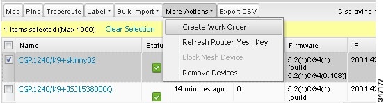
The Work Orders page appears (Config > Device Configuration > Work Orders). On that page, IoT FND adds the names of the selected FARs to the List of FAR Names field as a comma-separated list.
3.![]() Follow the steps in Creating Work Orders to create the work order.
Follow the steps in Creating Work Orders to create the work order.
For more information about work orders, see Managing Work Orders.
Refreshing the Router Mesh Key
If you suspect unauthorized access attempts to a FAR, refresh its mesh key.
Caution: Refreshing the router mesh key can result in MEs being unable to communicate with the FAR for a period of time until the MEs re-register with the FAR, which happens automatically.
To refresh the router mesh key, select a router or group of routers in the Browse Devices pane, and then in Default view:
1.![]() Check the check boxes of the of the FARs to refresh.
Check the check boxes of the of the FARs to refresh.
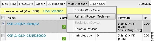
2.![]() Choose More Actions > Refresh Router Mesh Key from the drop-down menu.
Choose More Actions > Refresh Router Mesh Key from the drop-down menu.
Managing Embedded Access Points on Cisco C819 and Cisco IR829 ISRs
IoT Field Network Director allows you to manage the following embedded access point (AP) attributes on C819 and IR829 ISRs:
■![]() Periodic inventory collection
Periodic inventory collection
■![]() Firmware update of APs when operating in Autonomous Mode
Firmware update of APs when operating in Autonomous Mode
Note: IoT Field Network Director can only manage APs when operating in Autonomous mode.
Note: Not all C800 Series and IR800 routers have embedded APs. A C800 ISR features matrix is here. The IR800 ISR features matrix is here.
Using Router Filters
To refine the list of displayed routers, use the built-in router filters under ROUTERS in the Browse Devices pane or saved custom searches in the Quick View pane (left pane). For example, to display all operational FARs, click the Up group under ROUTERS in the Browse Devices pane. Click a filter to insert the corresponding search string in the Search Devices field. For example, clicking the Up group under ROUTERS inserts the search string status:up in the Search Devices field.
Displaying Router Configuration Groups
Use the Browse Devices pane to display the router devices that belong to one of the groups listed under ROUTERS.
Displaying Router Firmware Groups
Use the Browse Devices pane to display the router devices that belong to one of the groups listed under ROUTER FIRMWARE GROUPS.
Displaying Router Tunnel Groups
Use the Browse Devices pane to display the router devices that belong to one of the groups listed under ROUTER TUNNEL GROUPS.
Managing Mesh Endpoints
To manage MEs, view the Devices > Field Devices page. By default, the page displays the MEs in List view. This section includes the following topics:
■![]() Viewing Mesh Endpoints in Default View
Viewing Mesh Endpoints in Default View
■![]() Viewing Mesh Endpoints in Map View
Viewing Mesh Endpoints in Map View
■![]() Displaying Mesh Endpoint Configuration Groups
Displaying Mesh Endpoint Configuration Groups
■![]() Displaying Mesh Endpoint Firmware Groups
Displaying Mesh Endpoint Firmware Groups
Viewing Mesh Endpoints in Default View
When you open the Field Devices page in Default view, IoT FND lists all FAN devices and basic device properties. When you select an ENDPOINT device or group in the Browse Devices pane, IoT FND provides tabs to display additional ME property views:
Each one of these views displays different sets of device properties. For example, the Firmware view displays the device properties that fall under the firmware category, such as Hardware ID, Firmware Group, and FW Uploaded Version.
For information on how to customize ME views, see Customizing Device Views.
For information about the device properties displayed in each view, see Device Properties.
For information about the common actions in these views (for example, adding labels and changing device properties) that also apply to other devices, see Common Device Operations.
Viewing Mesh Endpoints in Map View
To view MEs in Map view, select Enable map in <user> > Preferences, and click the Map tab.
Blocking Mesh Devices
If you suspect unauthorized access attempts to a mesh device, block it from accessing IoT FND.
Caution: If you block an ME, you cannot unblock it using IoT FND. To re-register the ME with IoT FND, you must escalate and get your ME administrator involved.
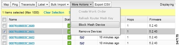
To block an ME device, in Default view:
1.![]() Check the check boxes of the mesh devices to refresh.
Check the check boxes of the mesh devices to refresh.
2.![]() Choose More Actions > Block Mesh Device from the drop-down menu.
Choose More Actions > Block Mesh Device from the drop-down menu.
Displaying Mesh Endpoint Configuration Groups
You can use the Browse Devices pane to display the ME devices that belong to one of the groups listed under MESH DEVICE CONFIGURATION GROUPS.
Displaying Mesh Endpoint Firmware Groups
You can use the Browse Devices pane to display the ME devices that belong to one of the groups listed under ENDPOINTS.
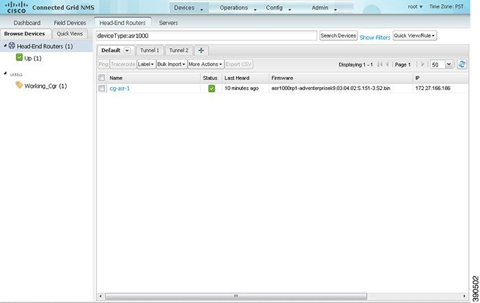
Managing Head-End Routers
To manage head-end routers (HERs), open the Head-End Routers page by choosing Devices > Head-End Routers (Head-End Routers Page). Unless Enable Map is selected in user preferences, by default, the page displays the HERs in List view. When you open the Head-End Routers page in List view, IoT FND displays the Default list view. This view displays basic HER device properties. In addition, IoT FND provides these tabs to display additional HER property views:
Each one of these views displays different sets of device properties. These views display information about the HER tunnels.
Figure 2 Head-End Routers Page
For information on how to customize HER views, see Customizing Device Views.
For information about the device properties displayed in each view, see Device Properties.
For information about the common actions in these views (for example, adding labels and changing device properties) that also apply to other devices, see Common Device Operations.
Managing Servers
To manage servers, open the Servers page by choosing Devices > Servers. By default, the page displays the servers in List view. When you open the Servers page in List view, IoT FND displays the Default list view. This view displays basic server device properties. To obtain information about a server, click its name.
To add additional views, see Customizing Device Views.
For more information about the device properties displayed in each view, see Device Properties.
For information about the common actions in this view, see Common Device Operations.
Managing NMS Servers
In the Browse Devices pane, NMS servers appear under NMS Servers. In single-NMS server deployments, only one server appears under NMS Servers. In cluster deployments, multiple NMS servers appear under NMS Servers. To filter the list pane:
■![]() To display all NMS servers, click NMS Servers in the Browse Devices pane.
To display all NMS servers, click NMS Servers in the Browse Devices pane.
Managing Database Servers
In the Browse Devices pane, IoT FND database servers appear under Database Servers. In single-server deployments, only one database server appears under Database Servers. If a secondary database is configured, it also appears under the same entry.
■![]() To display all database servers in List view, click Database Servers in the Browse Devices pane.
To display all database servers in List view, click Database Servers in the Browse Devices pane.
■![]() To only display servers that are operational, click Up.
To only display servers that are operational, click Up.
■![]() To only display servers that are non-operational, click Down.
To only display servers that are non-operational, click Down.
Common Device Operations
This section describes how to use IoT FND to manage and view information about devices, and includes the following topics:
■![]() Changing the Sorting Order of Devices
Changing the Sorting Order of Devices
■![]() Displaying Detailed Device Information
Displaying Detailed Device Information
■![]() Using Filters to Control the Display of Devices
Using Filters to Control the Display of Devices
■![]() Performing Bulk Import Actions
Performing Bulk Import Actions
Selecting Devices
In List view, IoT FND lets you select devices on a single page and across pages. When you select devices, a yellow bar displays that maintains a count of selected devices and has the Clear Selection and Select All commands. The maximum number of devices you can select is 1000. Perform the following to select devices:
■![]() To select devices across all pages, click Select All.
To select devices across all pages, click Select All.
■![]() To select all devices listed on a page, check the check box next to Name.
To select all devices listed on a page, check the check box next to Name.
■![]() To select a group of devices, check the check boxes of individual devices listed on a page and across pages. The count increments with every device selected, and selections on all pages are retained.
To select a group of devices, check the check boxes of individual devices listed on a page and across pages. The count increments with every device selected, and selections on all pages are retained.
Customizing Device Views
IoT FND lets you customize device views. For List views you can:
■![]() Specify the properties to display in the columns for each view (see Device Properties by Category for available properties)
Specify the properties to display in the columns for each view (see Device Properties by Category for available properties)
Adding Device Views
To add a custom device view tab to a device page in list view:
2.![]() In the Add New View dialog box, enter the name of the new tab.
In the Add New View dialog box, enter the name of the new tab.
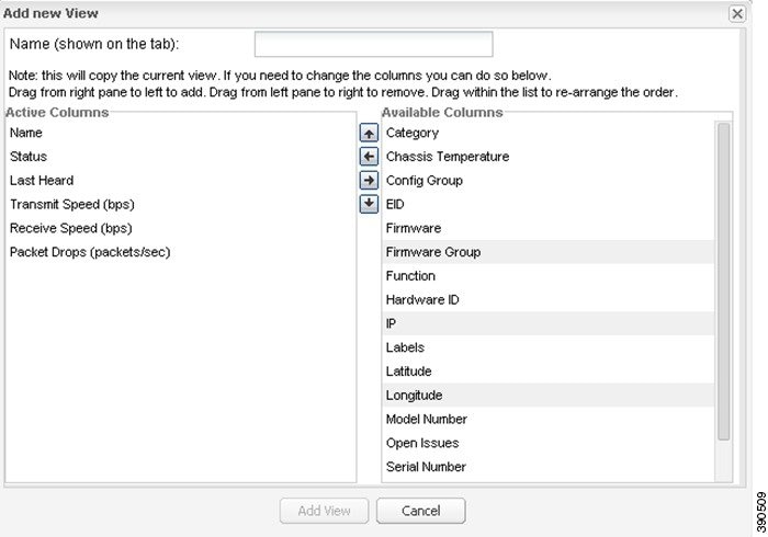
3.![]() Add properties to the Active Columns list by selecting them from the Available Columns list, and then clicking the left arrow button, or dragging them into the Active Columns list.
Add properties to the Active Columns list by selecting them from the Available Columns list, and then clicking the left arrow button, or dragging them into the Active Columns list.
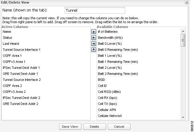
Editing Device Views
1.![]() Click the drop-down arrow on the desired tab.
Click the drop-down arrow on the desired tab.
2.![]() In the Edit/Delete View dialog box:
In the Edit/Delete View dialog box:
a.![]() To remove properties from the Active Columns list, select those properties and click the right-arrow button or drag them out of the Active Columns list.
To remove properties from the Active Columns list, select those properties and click the right-arrow button or drag them out of the Active Columns list.
b.![]() To add properties to the Active Columns list, select those properties from the Available Columns list and click the left-arrow button, or drag them into position in the Active Columns list.
To add properties to the Active Columns list, select those properties from the Available Columns list and click the left-arrow button, or drag them into position in the Active Columns list.
c.![]() To change the sort order of the active columns, use the up- and down-arrow buttons, or drag them to the desired position.
To change the sort order of the active columns, use the up- and down-arrow buttons, or drag them to the desired position.
Deleting Device Views
1.![]() Click the arrow on the tab of the device view to delete.
Click the arrow on the tab of the device view to delete.
2.![]() In the Edit/Delete View dialog box, select the desired label in the Active Columns pane.
In the Edit/Delete View dialog box, select the desired label in the Active Columns pane.
Viewing Devices in Map View
IoT FND provides a map view for visualizing device information based on geographic location. In Map view, IoT FND displays a Geographic Information System (GIS) map and uses GIS Map services to show device icons on the map based on the latitude and longitude information of the device. When this information is not defined for a device, IoT FND does not display the device on the map.
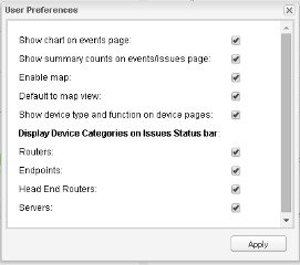
1.![]() Choose <user> > Preferences, check the Enable map check box, and click Apply.
Choose <user> > Preferences, check the Enable map check box, and click Apply.
2.![]() Choose Devices > Field Devices.
Choose Devices > Field Devices.
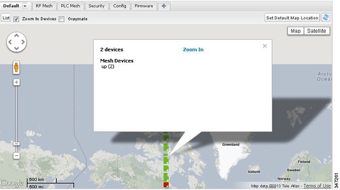
By default, IoT FND displays all devices registered in its database on the map. Depending on the zoom level of the map and the device count, individual device icons might not display. Instead, IoT FND displays device group icons.
To view individual devices, zoom in until the device icons appear. You can also click on a device to display a popup window that includes the Zoom In link to move the map display to the device level.
IoT FND displays the device count next to each device group or category in the Browse Devices pane (left pane).
| ■ |
| IoT FND changes the map region based on your selection and displays the devices found by the filter. For example, you can use the Routers > Up filter to display all FARs that are up and running. You can also use saved custom filters in the Quick View pane (left pane) to filter the device view. For information about creating custom filters, see Creating a Quick View Filter. |
| ■ |
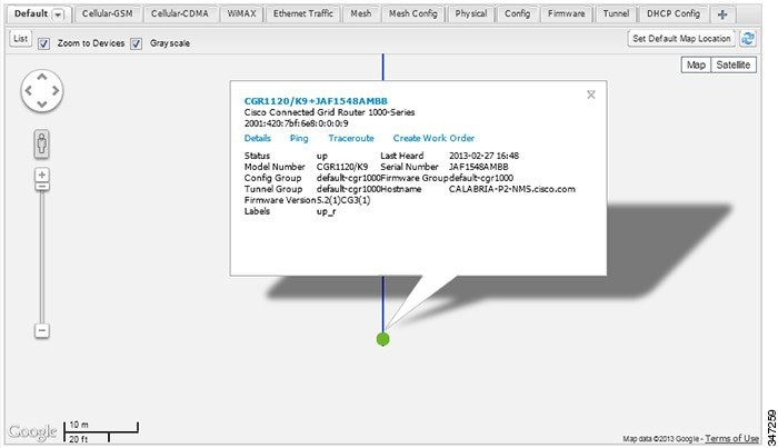
A popup window displays listing basic device or group information.
| ■ |
You can also ping the device, perform a trace route, and create a work order from this window.
4.![]() Close the Device popup window to view the RPL tree associated with the device. See Configuring RPL Tree Polling
Close the Device popup window to view the RPL tree associated with the device. See Configuring RPL Tree Polling
The RPL tree connection displays as blue or orange lines; where blue indicates that the link is down, and orange indicates that the link is up.
 ) to update the Map view.
 Configuring Map Settings
In Map view, IoT FND lets you configure these settings for maps:
■![]() Automatically zoom to devices
Automatically zoom to devices
■![]() Default map location (set to North America by default)
Default map location (set to North America by default)
1.![]() Choose Devices > Field Devices.
Choose Devices > Field Devices.
Changing the Sorting Order of Devices
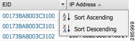
To change the sorting order of devices, click the right side of the column heading and choose a sort command from the drop-down menu.
Exporting Device Information
IoT FND lets you export the device properties of the selected devices in List view. IoT FND exports only properties in the current view.
To export device information displayed in the current view, in List view:
1.![]() Select the devices to export by checking their corresponding check boxes.
Select the devices to export by checking their corresponding check boxes.
3.![]() Click Yes in the confirmation dialog box.
Click Yes in the confirmation dialog box.
IoT FND creates a CSV file, export.csv, containing the information that displays in the List view pane. By default, IoT FND saves this file to your default download directory. When a file with the same name exists, IoT FND adds a number to the default filename (for example, export-1.csv and export-2.csv).
The export.csv file consists of one header line defining the exported fields followed by one or more lines, each representing a device. Here is an example of an export of selected devices from the Field Devices page:
Pinging Devices
When troubleshooting device issues, ping registered devices to rule out network connectivity issues. If you can ping a device, it is accessible over the network.
To ping selected devices, in List view:
1.![]() Check the check boxes of the devices to ping.
Check the check boxes of the devices to ping.
Note: If the status of a device is Unheard, a ping gets no response.
A window displays the ping results. If you check the check box for Auto Refresh, IoT FND pings the device at predefined intervals until you close the window. Click the Refresh button to ping the device at any time.
Tracing Routes to Devices
The Traceroute command lets you determine the route used to reach a device IP address.
To trace routes to selected devices, in List view:
1.![]() Check the check boxes of the devices to trace.
Check the check boxes of the devices to trace.
Note: You can only trace routes to devices registered with IoT FND. If the status of a device is Unheard, you cannot trace the route to it.
A window displays with the route-tracing results.

Expand the Result column to view complete route information.
Click the Refresh button to resend the Traceroute command. Check the Auto Refresh check box to resend the Traceroute command at predefined intervals until you close the window.
Managing Device Labels
You use labels to create logical groups of devices to facilitate locating devices and device management.
Managing Labels
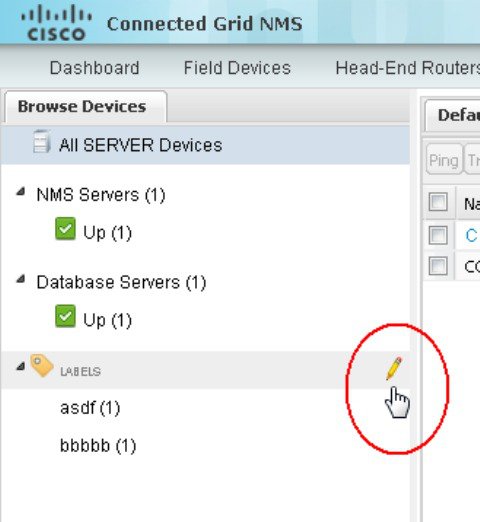
You use the Label Management window to display all custom labels, label properties, and search for custom labels.
To manage labels, in the Browse Device pane on any devices page:
1.![]() Hover your mouse over LABELS and click the edit icon (
Hover your mouse over LABELS and click the edit icon ( ).
).
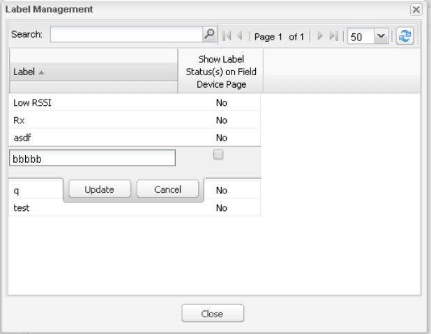
2.![]() Click Update to accept label property changes or Cancel to retain label properties.
Click Update to accept label property changes or Cancel to retain label properties.
Adding Labels
To add labels to selected devices, in List view:
1.![]() Check the check boxes of the devices to label.
Check the check boxes of the devices to label.
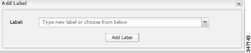
3.![]() Enter the name of the label or choose an existing label from the drop-down menu.
Enter the name of the label or choose an existing label from the drop-down menu.
Tip: You can add multiple labels to one device.
To add labels in bulk, see Adding Labels in Bulk.
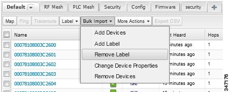
Removing Labels
To remove labels from selected devices, in List view:
1.![]() Check the check boxes of the devices from which to remove the label.
Check the check boxes of the devices from which to remove the label.
2.![]() Choose Label > Remove Label.
Choose Label > Remove Label.
To remove labels in bulk, see Removing Labels in Bulk.
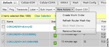
Removing Devices
Caution: When you remove FARs, IoT FND returns all the leased IP addresses associated with these devices to the Cisco Network Registrar (CNR) server and removes the corresponding tunnels from the HERs.
To remove devices, in List view:
1.![]() Check the check boxes of the devices to remove.
Check the check boxes of the devices to remove.
Displaying Detailed Device Information
IoT FND keeps detailed information about every device in the system. To access detailed information about a device, click its name or EID.
■![]() Detailed Information Displayed
Detailed Information Displayed
■![]() Actions You Can Perform from the Detailed Device Information Page
Actions You Can Perform from the Detailed Device Information Page
Detailed Information Displayed
Note: IoT FND automatically refreshes the detailed information without the need to reload the page.
Server Information
IoT FND displays the following information about the system running the NMS and database servers.
|
|
|
|---|---|
HER, FAR, and ME Information
IoT FND groups the detailed device information it displays about HERs, FARs, and MEs into the following categories:
|
|
|
|---|---|
| Displays detailed device information (see Device Properties). For FARs and MEs, IoT FND also displays charts (see Viewing Device Charts). |
|
| Displays information about events associated with the device. |
|
| Displays the configurable properties of a device (see Device Properties). You can configure these properties by importing a CSV file specifying the properties to configure and their new values, as described in Changing Device Configuration Properties. |
|
| Displays the mesh routing tree. For FARs, the Mesh Routing Tree pane displays all the possible routers from the MEs to the FAR. For MEs, the Mesh Routing Tree pane displays the mesh route to the FAR. |
|
| Displays the type of mesh link traffic over time in bits per second. |
|
| Lists metrics and session data for the TCP raw sockets (see Table 28) |
|
| Lists inventory (configuration) details and metrics for the attached access point. |
|
| Lists the running configuration file for the attached access point. |
Actions You Can Perform from the Detailed Device Information Page
Depending on device type, the Detailed Device Information page lets you perform these actions:
|
|
|
|---|---|
| Displays a popup window with a map location of the device. This is the equivalent of entering eid: Device_EID in the search field in Map View. |
|
| Sends a ping to the device to determine its network connectivity. See Pinging Devices |
|
| Traces the route to the device. See Tracing Routes to Devices |
|
| Instructs the device to send metrics to IoT FND. Note: IoT FND assigns historical values for metrics for each device. To access historical metric values, use the GetMetricHistory North Bound API call. |
|
| Refreshes the router ME key. See Refreshing the Router Mesh Key |
|
| Creates a work order. See Creating Work Orders |
|
| Synchronizes the configuration membership for this device. See Synchronizing Endpoint Membership |
|
| Click Sync Firmware Membership to synchronize the firmware membership for this device, and then click Yes to complete the process. |
|
Using Filters to Control the Display of Devices
Depending on your deployment, the number of devices managed by IoT FND can be very large (IoT FND supports up to 10 million devices). To facilitate locating and displaying devices in Map View and List view, IoT FND provides filters and lets you add customized filters. Filters are listed in the Browse Devices and Quick View tabs.
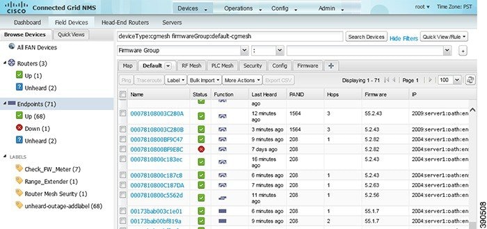
Browse Devices Filters
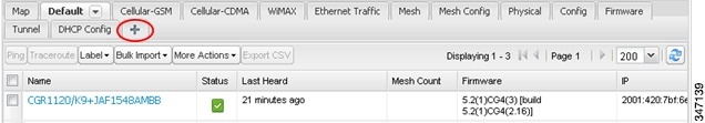
Built-in device filters display in the Browse Devices pane. These filters control the display of devices in List and Map views. For every filter entry, IoT FND provides a device count in parenthesis. IoT FND automatically updates the device count without having to reload the page. In the example in Built-in Filter to Search for MEs, the top-level Endpoints label is selected, which inserts the following built-in filter in the Search Devices field: deviceType:cgmesh firmwareGroup:default-cgmesh.
Figure 3 Built-in Filter to Search for MEs
Creating and Editing Quick View Filters
The Quick View pane displays custom filters. Click a filter in this pane to view the devices that fulfill the search criteria defined in the filter.
Creating a Quick View Filter
To create a Quick View filter:
1.![]() On any device page, click Show Filters and add filters to the Search field.
On any device page, click Show Filters and add filters to the Search field.
For more information about adding filters, see Adding a Filter.
2.![]() From the Quick View/Rule drop-down menu, choose Create Quick View.
From the Quick View/Rule drop-down menu, choose Create Quick View.
3.![]() In the Name field of the Save Quick View dialog box, enter the name for the Quick View filter.
In the Name field of the Save Quick View dialog box, enter the name for the Quick View filter.
Editing a Quick View Filter
To edit or delete a Quick View filter:
1.![]() Click the Quick View tab and select the filter to edit.
Click the Quick View tab and select the filter to edit.
2.![]() From the Quick View/Rule drop-down menu, choose Edit Quick View.
From the Quick View/Rule drop-down menu, choose Edit Quick View.
3.![]() In the Update Quick View dialog box, make the necessary modifications, and then click Save.
In the Update Quick View dialog box, make the necessary modifications, and then click Save.
Adding a Filter
To add a filter to the Search field:
1.![]() If the Add Filter fields are not present under the Search field, click Show Filters.
If the Add Filter fields are not present under the Search field, click Show Filters.
2.![]() From the Label drop-down menu, choose a filter.
From the Label drop-down menu, choose a filter.
The drop-down menu defines filters for all device information categories. For more information about these categories, see Working with Router Views.
3.![]() From the Operator (:) drop-down menu, choose an operator.
From the Operator (:) drop-down menu, choose an operator.
For more information about operators, see Filter Operators. If you choose a numeric metric from the Label menu (for example, Transmit Speed), you can specify a range of values in the filter you are adding. For date/time filters, “between” is the operator. Use the calendar buttons to specify the date range for the filter.
4.![]() In the Value field, enter a value to match or a range of values in the case of numeric metrics or select an available value from the drop-down menu.
In the Value field, enter a value to match or a range of values in the case of numeric metrics or select an available value from the drop-down menu.
5.![]() Click the Add (+) button to add the filter to the existing filter syntax in the Search field.
Click the Add (+) button to add the filter to the existing filter syntax in the Search field.
6.![]() (Optional) Repeat the process to continue adding filters.
(Optional) Repeat the process to continue adding filters.
Filter Operators
Filter Operators describes the operators you can use to create filters.
|
|
|
|---|---|
Search Syntax
IoT FND supports this simple query language syntax:
Filter := fieldname operator value
operator := < | <= | > | >= | <> | = | :
Note the following when creating filters to search fields:
■![]() Each field has a data type (String, Number, Boolean, and Date).
Each field has a data type (String, Number, Boolean, and Date).
■![]() String fields can contain a string, and you can search them using string equality (“:”).
String fields can contain a string, and you can search them using string equality (“:”).
■![]() Numeric fields can contain a decimal number (stored as a double-precision float), and you can search them using the numeric comparison operators (“>”, “>=”, “<“, “<=”, “<>”).
Numeric fields can contain a decimal number (stored as a double-precision float), and you can search them using the numeric comparison operators (“>”, “>=”, “<“, “<=”, “<>”).
■![]() Boolean fields can contain the strings “true” or “false”.
Boolean fields can contain the strings “true” or “false”.
■![]() Date fields can contain a date in this format: yyyy-MM-dd HH:mm:ss:SSS. You can search dates using numeric comparison operators.
Date fields can contain a date in this format: yyyy-MM-dd HH:mm:ss:SSS. You can search dates using numeric comparison operators.
Filter Examples describes filter examples.
|
|
|
|---|---|
|
|
|
|
|
|
|
|
Finds all CGR 1000s in the Nevada group that are up and running. |
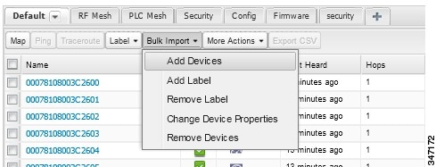
Performing Bulk Import Actions
In IoT FND, you can perform these bulk import device actions:
Adding Devices in Bulk
The Add Devices option in the Bulk Import drop-down menu lets you add FARs and HERs to IoT Field Network Director in bulk using a CSV file.
1.![]() On any device page, from the Bulk Import drop-down menu, choose Add Devices.
On any device page, from the Bulk Import drop-down menu, choose Add Devices.
2.![]() Click Browse to locate the CSV file containing the device information to import, and then click Open.
Click Browse to locate the CSV file containing the device information to import, and then click Open.
For more information about adding HERs, see Adding HERs to IoT FND.
For more information about adding FARs, see Adding FARs to IoT FND.
Note: For FARs, you can also use the Notice-of-Shipment XML file provided by your Cisco partner to import FARs.
Adding HERs to IoT FND
Configuring HERs Before Adding them to IoT FND
Before you can add an HER to IoT FND, configure the HER to allow management by IoT FND using Netconf over SSH as follows:
Where <her_hostname> is the hostname or IP address of the IoT FND server, and <domain.com> is the name of the domain name where the HER and IoT FND reside. The time-out value of 120 is required for large networks.
After configuring the HER to allow management by IoT FND, ensure that you can:
■![]() Ping the management interface of the HER.
Ping the management interface of the HER.
■![]() Access the management interface of the HER over SSH and vice versa.
Access the management interface of the HER over SSH and vice versa.
To add HERs, create a CSV file like the following example that consists of a header line followed by one or more lines, each representing an HER:
HER Import Fields describes the fields to include in the CSV file.
Note: For device configuration field descriptions, see Device Properties.
When you add an HER, IoT FND displays its status as Unheard. IoT FND changes the status to Up after it polls the HER. IoT FND polls HERs in the background every 15 minutes to collect device metrics, so it should take no more than 15 minutes for the status of HERs to change to Up after you add them to IoT FND. However, you can trigger the polling of HERs by clicking Refresh Metrics (Refresh Metrics).
Adding FARs to IoT FND
Typically, when adding FARs to IoT FND, you use the Notice-of-Shipment XML file sent to you by your Cisco partner. This file contains an R record for every FAR shipped to you. This is an example of an R record for a CGR:
Note: For a list of all Device Properties that you can configure using the XML configuration template go to Device Properties.
FAR Import Fields describes the FAR properties defined in the R record used in this example:
Mapping FARs to HERs
After you determine the FAR-to-HER mapping, which is essential for tunnel provisioning, you can configure the mapping in IoT FND in one of two ways:
■![]() Adding the mapping information to every FAR record in the Notice-of-Shipment XML file.
Adding the mapping information to every FAR record in the Notice-of-Shipment XML file.
■![]() Creating a CSV file specifying the mapping of FARs to HERs.
Creating a CSV file specifying the mapping of FARs to HERs.
Adding FAR-to-HER Mappings to the Notice-of-Shipment XML File
To map a FAR to an HER, add the tunnelHerEid and ipsecTunnelDestAddr1 HER properties to the FAR record in the Notice-of-Shipment XML file.
■![]() The tunnelHerEid property specifies the EID of the HER
The tunnelHerEid property specifies the EID of the HER
■![]() The ipsecTunnelDestAddr1 property specifies the tunnel IP address of the HER.
The ipsecTunnelDestAddr1 property specifies the tunnel IP address of the HER.
Adding FAR-to-HER Mappings to a CSV File
To map FARs to HERs using a CSV file, add a line for every FAR-to-HER mapping. The line must specify the EID of the FAR, the EID of the corresponding HER, and the tunnel IP address of the HER, as in this example for a CGR:
Removing Devices in Bulk
You can remove devices in bulk using a CSV file listing the EIDs of the devices to remove.
Caution: When you remove FARs, IoT FND returns all the leased IP addresses associated with these devices to CNR and removes the corresponding tunnels from the HERs.
1.![]() Choose Devices > Device Type.
Choose Devices > Device Type.
2.![]() Choose Bulk Import > Remove Devices.
Choose Bulk Import > Remove Devices.
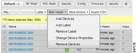
3.![]() Click Browse to locate the CSV file containing the devices to delete, and then click Choose.
Click Browse to locate the CSV file containing the devices to delete, and then click Choose.
This is an example of the CSV format expected. In this case, the CSV file specifies three CGRs and one HER:
The Status section of the Remove Devices window displays the status of the operation. The History section describes additional information about the operation. If there was any failure, click the corresponding link in the Failure# column to get more information about the error.
Changing Device Properties in Bulk
IoT FND lets you configure device properties in bulk using a CSV file. For example, this CSV file changes the latitude and longitude for the specified HER:
To configure device properties in bulk:
1.![]() On any device page, choose Bulk Import > Change Device Properties.
On any device page, choose Bulk Import > Change Device Properties.
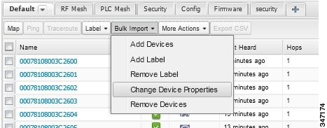
2.![]() Click Browse to locate the CSV containing the list of devices and corresponding properties to configure, and then click Open.
Click Browse to locate the CSV containing the list of devices and corresponding properties to configure, and then click Open.
Adding Labels in Bulk
You can group devices logically by assigning them labels. Labels are independent of device type, and devices of any type can belong to any label. A device can also have multiple labels. Unlike configuration groups and firmware groups, there are no policies or metadata associated with labels.
IoT FND lets you add labels in bulk using a CSV file. In the CSV file, specify the list of devices to be labeled.
1.![]() On any device page, choose Bulk Import > Add Label.
On any device page, choose Bulk Import > Add Label.
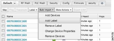
2.![]() Click Browse to locate the CSV file that contains the list of devices to label, and then click Open.
Click Browse to locate the CSV file that contains the list of devices to label, and then click Open.
This is an example of the expected CSV format:
3.![]() In the Label field, enter the label or choose one from the drop-down menu.
In the Label field, enter the label or choose one from the drop-down menu.
The label appears in the Browse Devices tab (left pane) under LABELS.
Removing Labels in Bulk
IoT FND lets you delete labels in bulk using a CSV file.
1.![]() On any device page, choose Bulk Import > Remove Label.
On any device page, choose Bulk Import > Remove Label.
2.![]() Click Browse to locate the CSV containing the list of devices to remove the label from, and then click Open.
Click Browse to locate the CSV containing the list of devices to remove the label from, and then click Open.
Configuring Rules
A IoT FND rule defines a filter and actions that IoT FND performs after an event or after it receives metrics that match the search criteria defined in the filter. Rules can check for event conditions and metric thresholds.
For example, whenever the status of a FAR in a configuration group changes to Up, you can add a custom message to the server log (server.log) and add the appropriate labels to the device. This helps you automate the process of adding labels to devices.
When working with rules, you can do the following:
■![]() Add rules with conditions and actions.
Add rules with conditions and actions.
■![]() Define a rule with a condition using a device search query, which matches devices according to properties and metrics.
Define a rule with a condition using a device search query, which matches devices according to properties and metrics.
■![]() Define a rule with a condition using an event search query, which matches events according to event properties.
Define a rule with a condition using an event search query, which matches events according to event properties.
■![]() Define a rule with an action that adds labels to matching devices or to the devices that sent a matching event.
Define a rule with an action that adds labels to matching devices or to the devices that sent a matching event.
■![]() Define a rule with an action that removes a label from a matching device or the device that sent a matching event.
Define a rule with an action that removes a label from a matching device or the device that sent a matching event.
■![]() Define a rule with an action that places a user alert event into the log, which includes a user-defined message.
Define a rule with an action that places a user alert event into the log, which includes a user-defined message.
Viewing and Editing Rules
IoT FND displays the list of rules stored in its database. Rule Fields describes the fields displayed in the list.
2.![]() To edit a rule, click its name.
To edit a rule, click its name.
For information on how to edit rules, see Adding a Rule.
Adding a Rule
Note: If you enter invalid characters (for example, “=”, “+”, and “~”), IoT FND displays a red alert icon, highlights the field in red, and disables the OK![]() button.
button.
4.![]() To activate the rule, check the Active? check box.
To activate the rule, check the Active? check box.
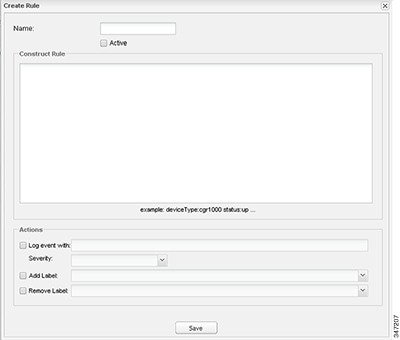
5.![]() Enter the syntax of the rule.
Enter the syntax of the rule.
Use the same syntax used for creating filters. See Search Syntax.
6.![]() Check the check box of at least one action:
Check the check box of at least one action:
| ■ – – For example, if you enter Red Alert in this field, set the Severity to CRITICAL and enter CHECK ROUTER in the Event Name field, the eventMessage field in the logged entry for the event that matches the rule is set to Red Alert, as shown in this sample entry from the server log (server.log): |
| In IoT FND, the message you define in the Log event with field appears in the Message field of the matching event entries listed on the Events page (Operations > Events), and the new Event Name is a new search filter. |
| ■ |
| ■ |
| ■ |
Activating Rules
IoT FND does not apply rules if they are not activated.
2.![]() Check the check boxes of the rules to activate.
Check the check boxes of the rules to activate.
Deactivating Rules
If you deactivate a rule, IoT FND does not apply it.
2.![]() Check the check boxes of the rules to deactivate.
Check the check boxes of the rules to deactivate.
Deleting Rules
2.![]() Check the check boxes of the rules to delete.
Check the check boxes of the rules to delete.
Configuring Devices
This section describes how to configure devices in IoT FND, including:
■![]() Configuring Device Group Settings
Configuring Device Group Settings
■![]() Editing the ROUTER Configuration Template
Editing the ROUTER Configuration Template
■![]() Editing the ENDPOINT Configuration Template
Editing the ENDPOINT Configuration Template
■![]() Pushing Configurations to FARs
Pushing Configurations to FARs
■![]() Pushing Configurations to Endpoints
Pushing Configurations to Endpoints
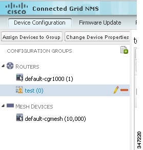
Configuring Device Group Settings
IoT FND uses groups to manage devices in bulk. When you add FARs to IoT Field Network Director, IoT FND automatically adds them to the appropriate default ROUTER configuration groups, for example, default-cgr1000. When you add MEs (meters and range extenders), IoT FND adds them to the default ENDPOINT configuration group, default-cgmesh.
■![]() Changing Device Configuration Properties
Changing Device Configuration Properties
■![]() Moving Devices to Another Group
Moving Devices to Another Group
■![]() Listing Devices in a Configuration Group
Listing Devices in a Configuration Group
■![]() Configuring Periodic Inventory Notification and Mark-Down Time
Configuring Periodic Inventory Notification and Mark-Down Time
Creating Device Groups
By default, IoT FND defines these device groups:
|
|
|
|---|---|
Each default group defines a default configuration template that you can push to all devices in that group. However, if you need to apply a different template to a group of devices, create a new group and modify its default configuration template as needed.
Note: You cannot delete the default groups, but you can change their names, although we do not recommend it. Also, the default ROUTER and ENDPOINT groups use the same icon, while custom groups use a different icon. See IoT FND Icons for icon definitions.
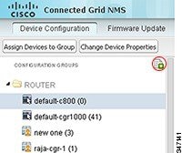
Creating ROUTER Groups
Note: CGRs, IR800s, and ISR800s can coexist on a network; however, you must create custom templates that includes all router types.
To create a ROUTER configuration group:
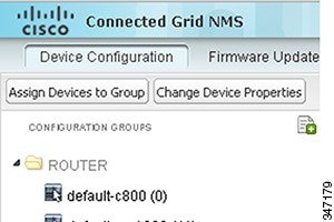
1.![]() Choose Config > Device Configuration.
Choose Config > Device Configuration.
2.![]() Select the default group: default-cgr1000 default-ir800.
Select the default group: default-cgr1000 default-ir800.
3.![]() Click the Add Group button.
Click the Add Group button.
4.![]() Enter the name of the group.
Enter the name of the group.
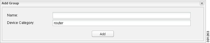
The device category is selected by default.
Note: If you enter invalid characters (for example, “=”, “+”, and “~”), IoT FND displays a red alert icon, highlights the field in red, and disables the OK![]() button.
button.
The new group entry appears in the ROUTERS list (left pane).
■![]() To change the name of a group, see Renaming a Device Configuration Group.
To change the name of a group, see Renaming a Device Configuration Group.
■![]() To remove a group, see Deleting Device Groups.
To remove a group, see Deleting Device Groups.
Creating ENDPOINT Groups
To create an ENDPOINT configuration group:
1.![]() Choose Config > Device Configuration.
Choose Config > Device Configuration.
2.![]() Select the default group (default-cgmesh).
Select the default group (default-cgmesh).
3.![]() Click the Add Group (
Click the Add Group ( ) button.
4.![]() Enter a name for the group.
Enter a name for the group.
Note: If you enter invalid characters (for example, “=”, “+”, and “~”), IoT FND displays a red alert icon, highlights the field in red, and disables the OK![]() button.
button.
The new group entry appears in the ENDPOINT list (left pane).
■![]() To change the name of a group, see Renaming a Device Configuration Group.
To change the name of a group, see Renaming a Device Configuration Group.
■![]() To remove a group, see Deleting Device Groups.
To remove a group, see Deleting Device Groups.
Changing Device Configuration Properties
You can change the configurable properties of devices by uploading a Device Properties CSV file with modified values for the devices.
To change device configuration properties:
1.![]() Choose Config > Device Configuration.
Choose Config > Device Configuration.
2.![]() Click Change Device Properties.
Click Change Device Properties.
3.![]() Click Browse and select the Device Properties CSV file to upload.
Click Browse and select the Device Properties CSV file to upload.
■![]() For a list of configurable device properties in IoT FND, see Device Properties.
For a list of configurable device properties in IoT FND, see Device Properties.
Moving Devices to Another Group
There are two ways to move devices from one configuration group to another:
Moving Devices to Another Configuration Group Manually
To move devices to another configuration group:
1.![]() Choose Config > Device Configuration.
Choose Config > Device Configuration.
2.![]() Select a group from the list of configuration groups (left pane).
Select a group from the list of configuration groups (left pane).
3.![]() Check the check boxes of the devices to move.
Check the check boxes of the devices to move.
4.![]() Click Change Configuration Group.
Click Change Configuration Group.
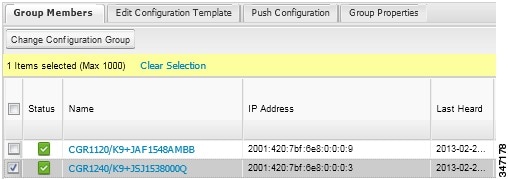
5.![]() From the drop-down menu in the dialog box, choose the target group for the devices.
From the drop-down menu in the dialog box, choose the target group for the devices.
Moving Devices to Another Configuration Group in Bulk
To move a large number of devices from one group to another, you can import a CSV file containing the list of the devices to move.
For example, this CSV file specifies the EIDs of three CGRs to move:
To move devices to another configuration group in bulk:
1.![]() Choose Config > Device Configuration.
Choose Config > Device Configuration.
2.![]() Click Assign Devices to Group.
Click Assign Devices to Group.
3.![]() Click Browse to locate the CSV file containing the list of devices to move, and then click Open.
Click Browse to locate the CSV file containing the list of devices to move, and then click Open.
4.![]() From the Group drop-down menu, choose the target group for the devices.
From the Group drop-down menu, choose the target group for the devices.
Listing Devices in a Configuration Group
To list the devices in a configuration group:
1.![]() Choose Config > Device Configuration.
Choose Config > Device Configuration.
2.![]() Select a group from the list of configuration groups (left pane).
Select a group from the list of configuration groups (left pane).
3.![]() To get more information about a device in the list, click its EID.
To get more information about a device in the list, click its EID.
Configuring Periodic Inventory Notification and Mark-Down Time
You can change the periodic inventory notification interval for a configuration group of FARs without affecting the logic that IoT FND uses to mark those FARs as Down. However, for this to happen, you must enable the periodic configuration notification frequency for the FAR group so that it is less than the mark-down timer.
You can configure the mark-down timer by clicking the Group Properties tab for the group and modifying the value of the Mark Routers Down After field.
Configuring Periodic Inventory Notification
To configure the periodic inventory notification interval for a ROUTER configuration group:
1.![]() Click Config > Device Configuration.
Click Config > Device Configuration.
2.![]() Select a ROUTER configuration group.
Select a ROUTER configuration group.
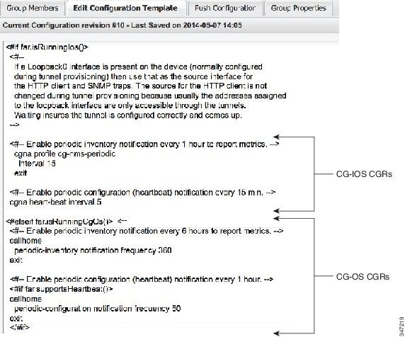
3.![]() Click Edit Configuration Template.
Click Edit Configuration Template.
Configuring the Mark-Down Timer
To configure the mark-down timer for a ROUTER configuration group:
1.![]() Click Config > Device Configuration.
Click Config > Device Configuration.
2.![]() Select a ROUTER configuration group.
Select a ROUTER configuration group.
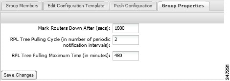
4.![]() In the Mark Routers Down After field, enter the number of seconds after which IoT FND marks the FARs as down if they do not send periodic configuration notifications (heartbeats) to IoT FND during that time.
In the Mark Routers Down After field, enter the number of seconds after which IoT FND marks the FARs as down if they do not send periodic configuration notifications (heartbeats) to IoT FND during that time.
Note: We recommend a 1:3 ratio of heartbeat interval to mark-down timer.
6.![]() Ensure that the periodic-configuration notification frequency in the configuration template is less than the value you entered the Mark Routers Down After field:
Ensure that the periodic-configuration notification frequency in the configuration template is less than the value you entered the Mark Routers Down After field:
a.![]() Click Edit Configuration Template.
Click Edit Configuration Template.
b.![]() Ensure that the value of the periodic-configuration notification frequency parameter is less than the Mark Routers Down After value.
Ensure that the value of the periodic-configuration notification frequency parameter is less than the Mark Routers Down After value.
Use a notification value that is at most one-third of the mark-down value. For example, if you choose a mark-down value of 3600 seconds (60 minutes), set the periodic-configuration notification frequency parameter to 20 minutes:
Note: The ability to control the periodic inventory notification interval and the periodic-configuration notification frequency applies to CGR image version 3.2.
Renaming a Device Configuration Group
To rename a device configuration group:
1.![]() Choose Config > Device Configuration.
Choose Config > Device Configuration.
2.![]() Select a group from the list of configuration groups (left pane).
Select a group from the list of configuration groups (left pane).
The Edit Group button displays as a pencil icon when you hover over the name of the group in the list.
4.![]() Enter the new name in the Rename Group dialog box, and then click OK.
Enter the new name in the Rename Group dialog box, and then click OK.
Note: If you enter invalid characters (for example, “=”, “+”, and “~”), IoT FND displays a red alert icon, highlights the field in red, and disables the OK![]() button.
button.
Deleting Device Groups
Note: Before deleting a group, move all devices in that group to another group. You cannot delete a non-empty group.
To delete a configuration group:
1.![]() Choose Config > Device Configuration.
Choose Config > Device Configuration.
2.![]() Select a group from the list of configuration groups (left pane).
Select a group from the list of configuration groups (left pane).
3.![]() Ensure that the group is empty.
Ensure that the group is empty.
 ).
).The Delete icon displays as a red minus sign when you hover over the name of the group in the list.
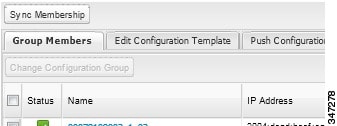
Synchronizing Endpoint Membership
MEs maintain information about the IoT FND group to which they belong. If the group information changes, the ME becomes out of sync. For example, if you rename an ME group, the members of the group might not be modified immediately (for example, due to a packet loss). If a device is out of sync, any operation you perform on the group through IoT FND does not reach the device. To ensure that the MEs remain in sync, use the Sync Membership button to push the group information to group members.
To send group information to MEs:
1.![]() Choose Config > Device Configuration.
Choose Config > Device Configuration.
2.![]() Select an ENDPOINT group (left pane).
Select an ENDPOINT group (left pane).
3.![]() Check the check boxes of the members in the group to sync.
Check the check boxes of the members in the group to sync.
5.![]() When prompted to synchronize membership for the group, click Yes.
When prompted to synchronize membership for the group, click Yes.
Devices sync for the first time after they register with IoT FND.
Editing the ROUTER Configuration Template
IoT FND lets you configure FARs in bulk using a configuration template. When a FAR registers with IoT FND, IoT Field Network Director pushes the configuration defined in the default template to the device and commits the changes to the router startup configuration. IoT FND then retrieves the running configuration from the router before changing the device status to Up.
To edit a ROUTER group configuration template:
1.![]() Choose Config > Device Configuration.
Choose Config > Device Configuration.
2.![]() Under CONFIGURATION GROUPS (left pane), select the group with the template to edit.
Under CONFIGURATION GROUPS (left pane), select the group with the template to edit.
3.![]() Click Edit Configuration Template.
Click Edit Configuration Template.
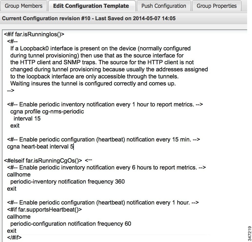
The template is expressed in FreeMarker syntax. For more information about FreeMarker, see Tunnel Provisioning Template Syntax.
Note: The router configuration template does not validate the configuration data entered. Verify the configuration before saving.
IoT FND commits the changes to the database and increases the template version number.
Editing the AP Configuration Template
IoT FND lets you configure APs in bulk using a configuration template. When the AP registers with IoT FND, it pushes the configuration defined in the default template to devices and commits the changes to the startup configuration. IoT FND then retrieves the running configuration from the AP before changing the device status to Up.
To edit a AP group configuration template:
1.![]() Choose Config > Device Configuration.
Choose Config > Device Configuration.
2.![]() Under CONFIGURATION GROUPS (left pane), select the C800 device group with embedded AP devices with the template to edit.
Under CONFIGURATION GROUPS (left pane), select the C800 device group with embedded AP devices with the template to edit.
3.![]() Click Edit AP Configuration Template.
Click Edit AP Configuration Template.
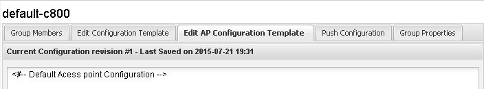
The template is expressed in FreeMarker syntax. For more information about FreeMarker, see Tunnel Provisioning Template Syntax.
Note: The AP configuration template does not validate the configuration data entered. Verify the configuration before saving.
IoT FND commits the changes to the database and increases the template revision number.
Enabling Dual PHY Support
You can configure CGR master and slave interfaces. For more information about configuring a dual-PHY WPAN interface, refer to Cisco Connected Grid WPAN Module for CGR 1000 Series Installation and CG-Mesh Configuration Guide (Cisco IOS).
Enabling Router GPS Tracking
You can enable GPS traps to trigger an event if the router moves a distance threshold, after a time threshold, or both. For example, you can configure stationary, pole-top CGR monitoring for a distance threshold, to detect movement from theft or pole incident; for mobile routers, set both thresholds to determine distance over time. The recommended distance threshold is 100 feet (30 m).
To enable GPS traps, uncomment these lines in the default configuration template.
Tip: Because GPS traps only generate Informational logs, we recommend that you create a rule-based event with high severity (such as CRITICAL) to inform the administrator of router movement. An example of this type of rule definition is: configGroup:name eventName:deviceLocChanged (see Adding a Rule).
Configuring SNMP v3 Informational Events
For Cisco IOS routers you configure SNMP v3 Informational Events to replace the default SNMP v3 traps. In CG-OS by default, SNMP v3 traps are configured for any IoT FND event-related changes that generate a trap on the router. IoT FND maps these traps to the corresponding event. For Cisco IOS routers, converting these SNMP v3 traps to SNMP v3 Informational Events sends an acknowledgment to the router for every event received from the router. The router then verifies that the trap was received by IoT FND. To enable SNMP v3 Informational Events, uncomment the following lines in the default configuration file and push the new configuration file to all router(s) in the group:
Editing the ENDPOINT Configuration Template
To edit an ENDPOINT configuration template:
1.![]() Choose Config > Device Configuration.
Choose Config > Device Configuration.
2.![]() Under CONFIGURATION GROUPS (left pane), select the ENDPOINT group with the template to edit.
Under CONFIGURATION GROUPS (left pane), select the ENDPOINT group with the template to edit.
3.![]() Click Edit Configuration Template.
Click Edit Configuration Template.
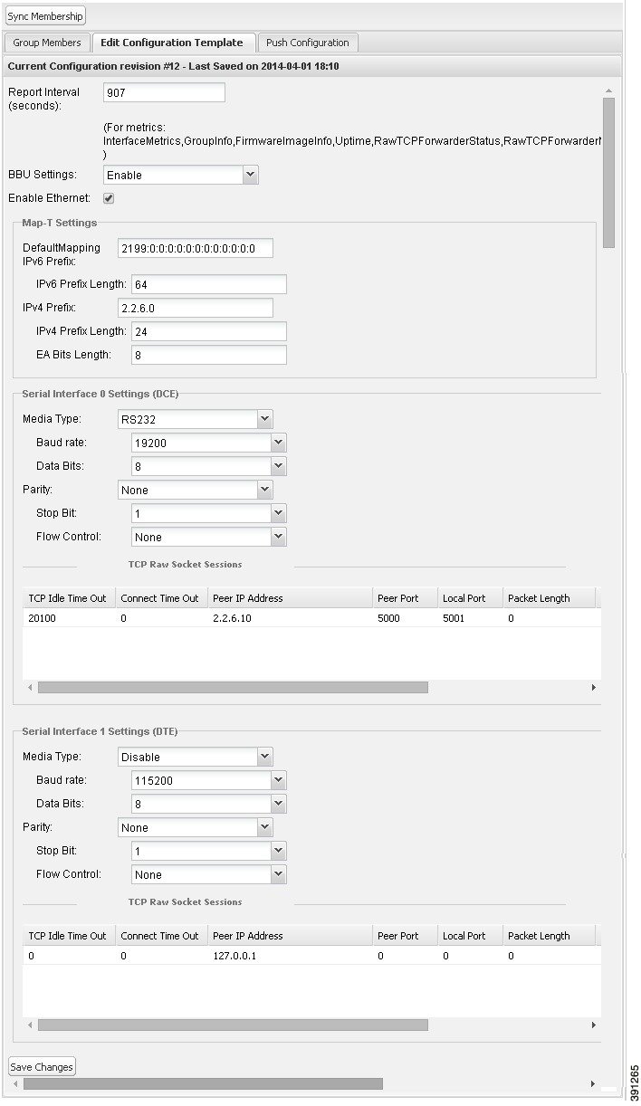
For example, in the Report Interval field, you can enter the number of seconds between data updates. By default, MEs send a new set of metrics every 28,800 seconds (8 hours).
You can change the following values on the Edit Configuration Template tab:
IoT FND commits the changes to the database and increases the version number.
Pushing Configurations to FARs
Note: CGRs, C800s, IR800s, and ISR 800s can coexist on a network; however, you must create custom configuration templates that includes both router types.
To push the configuration to FARs:
1.![]() Choose Config > Device Configuration.
Choose Config > Device Configuration.
2.![]() Select the group or subset of a group to push the configuration to in the CONFIGURATION GROUPS pane.
Select the group or subset of a group to push the configuration to in the CONFIGURATION GROUPS pane.
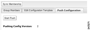
3.![]() Click the Push Configuration tab.
Click the Push Configuration tab.
4.![]() In the Select Operation drop-down menu, choose Push Router Configuration.
In the Select Operation drop-down menu, choose Push Router Configuration.
For C800 and IR800 groups with embedded AP devices, choose Push AP Configuration to push the AP configuration template.
The Push Configuration page displays the status of the push operation for every device in the group. If an error occurs while pushing configuration to a device, the error and its details display in the relevant columns.
In the Status column, one of these values appear:
Tip: To refresh the status information, click the Refresh button.
Enabling CGR SD Card Password Protection
Password protection for the SD card in the CGR helps prevent unauthorized access and prevents transference of the CGR SD card to another system with a different password.
Note: This does not apply to C800s or IR800s.
The Device Info pane displays CGR SD card password protection status in the Inventory section. The Config Properties tab displays the SD card password in the Router Credentials section.
To enable CGR SD card password protection:
1.![]() Choose Config > Device Configuration.
Choose Config > Device Configuration.
2.![]() Select the CGR group or CGRs to push the configuration to in the CONFIGURATION GROUPS pane.
Select the CGR group or CGRs to push the configuration to in the CONFIGURATION GROUPS pane.
3.![]() Select the Push Configuration tab.
Select the Push Configuration tab.

4.![]() In the Select Operation drop-down menu, choose Push SD Card Password.
In the Select Operation drop-down menu, choose Push SD Card Password.
6.![]() Select SD Card protection > Enable.
Select SD Card protection > Enable.
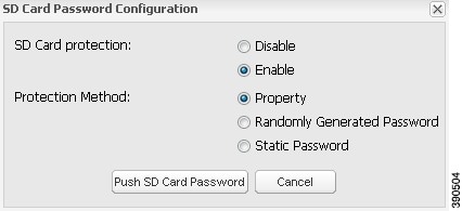
7.![]() Select the desired protection method:
Select the desired protection method:
| ■ |
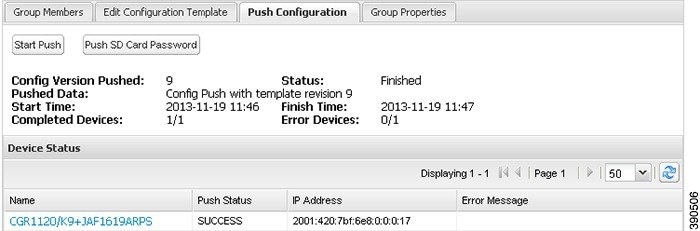
Pushing Configurations to Endpoints
To push configuration to mesh endpoints:
1.![]() Choose Config > Device Configuration.
Choose Config > Device Configuration.
2.![]() Select the group or subset of a group to push the configuration to in the ENDPOINT list.
Select the group or subset of a group to push the configuration to in the ENDPOINT list.
3.![]() Click the Push Configuration tab.
Click the Push Configuration tab.
Note: The Push Configuration tab supports a subnet view for cgmesh Endpoints that summarizes:
4.![]() In the Select Operation drop-down menu, choose Push Endpoint Configuration.
In the Select Operation drop-down menu, choose Push Endpoint Configuration.
The Push Configuration page displays the status of the push operation for every device in the group. If an error occurs while pushing configuration to a device, the error and its details display in the relevant columns.
In the Status column, one of these values appear:
To refresh the status information, click the Refresh button.
Managing a Guest OS
Cisco IOS CGRs support a virtual machine to run applications on a Guest OS (GOS) instance running beside the Cisco IOS virtual machine. The GOS is Linux. Applications running on the GOS typically collect statistics from the field for monitoring and accounting purposes. The Cisco IOS firmware bundle installs a reference GOS on the VM instance on the CGR. IoT FND supports the following role-based features on the GOS:
■![]() Upgrading the reference GOS in the Cisco IOS firmware bundle
Upgrading the reference GOS in the Cisco IOS firmware bundle
Note: IoT FND only supports the reference GOS provided by Cisco.
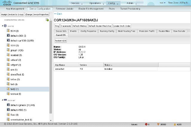
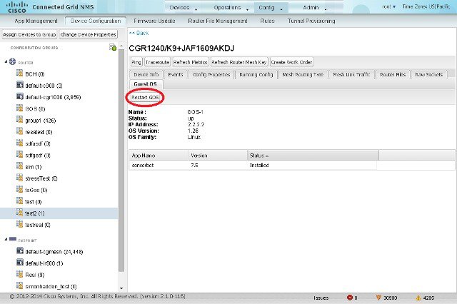
You manage and monitor a GOS on the Config > Device Configuration page, on the Guest OS tab.
Figure 4 Config > Device Configuration Page – Guest OS Tab Restart GOS Button
This section includes the following topics:
Installing a GOS
Depending on CGR factory configuration, a GOS may be present in the VM instance. The GOS installs with the Cisco IOS firmware bundle (see FAR Firmware Updates). The GOS, Hypervisor, and Cisco IOS all upgrade when you perform a Cisco IOS image bundle installation or update.
After any Cisco IOS install or upgrade, when IoT FND discovers a GOS, it checks if the initial communications setup is complete before it performs the required setup. The CGR must have a DHCP pool and Gigabit Ethernet 0/1 interface configured to provide an IP address and act as the gateway for the Guest OS. See the Cisco 1000 Series Connected Grid Routers Configuration Guides web portal for information on configuring the CGR.
Note: If IoT FND detects a non-Cisco OS is installed on the VM, the firmware bundle will not upload and the Cisco reference GOS will not install.
Managing GOS Applications
Applications (apps) run on the VM instance, but are not included in the Cisco IOS firmware bundle. You distribute GOS apps as standard app-<appname>-ver-<version>.zip files, and use the Config > App Management page to upload, install, start and stop, and uninstall GOS apps. The IoT FND internal backup and restore mechanism preserves existing apps during upgrades.
Note: For IoT FND GOS communications such as application uploads to the GOS using ssh, the gosPassword must be the CGR properties file. You upload the properties file in a CSV/XML upload. Without the gosPassword property, IoT FND cannot upload apps to a GOS.
Users with the GOS Application Management role enabled can upload, install, and deploy apps on Cisco IOS CGRs within your network.
Figure 5 Config > Apps Management Page–Last Job Status
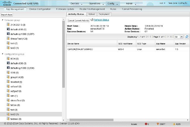
Managing GOS App Activities
You can manage app activities (jobs) on the Config > App Management Activity Status tab. The top pane (above the device list) displays job-related info for the last activity performed, which includes:
■![]() The start and stop time of the last activity.
The start and stop time of the last activity.
■![]() The number of devices with successful results and the number of devices with errored results.
The number of devices with successful results and the number of devices with errored results.
Activity Status Tab lists fields that display in the device list on the Activity Status tab.
|
|
|
|---|---|
The selected activity: Upload, Set to Run, Install, Start, Stop, Uninstall, and Delete Remote Package. |
|
On the Activity Status tab, you can also:
■![]() Click the Cancel Current Activity button to cancel any activity. Any activity in progress can be canceled.
Click the Cancel Current Activity button to cancel any activity. Any activity in progress can be canceled.
Uploading GOS Apps
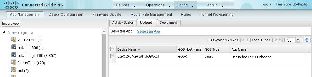
After GOS apps are imported to IoT FND, you can upload them for deployment on the GOS on Cisco IOS CGRs and IR800s, using the Config > Apps Management page Upload tab (Upload Tab). Apps are OS specific. If the GOS is Linux, any apps you upload must run on Linux.
To upload apps to IoT FND to deploy on Cisco IOS CGRs and IR800s, on the Config > Apps Management page:
1.![]() Select a firmware or configuration group in the left pane.
Select a firmware or configuration group in the left pane.
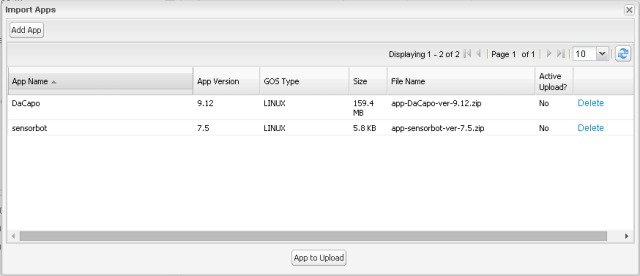
3.![]() Click Select an App or click the Import Apps button in the left pane.
Click Select an App or click the Import Apps button in the left pane.
The Import Apps dialog box displays apps already uploaded to the NMS server.
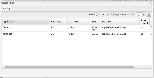
4.![]() In the Import Apps dialog box, click Add App.
In the Import Apps dialog box, click Add App.
5.![]() In the Add App dialog box, click Browse to navigate to the directory containing your app.
In the Add App dialog box, click Browse to navigate to the directory containing your app.
Note: Apps must be in the standard <appname>-<version>.zip file format.
6.![]() In the Open dialog box, select the app file, and click Open.
In the Open dialog box, select the app file, and click Open.
Note: Only one app may be uploaded at a time.
The app file uploads to the NMS server and displays in the App Name list.
8.![]() In the Add App dialog box, click the desired app to upload to CGRs, click Add to Upload, and click OK.
In the Add App dialog box, click the desired app to upload to CGRs, click Add to Upload, and click OK.
The app filename displays in the App Name list.
9.![]() In the App Name list, select the desired app to upload.
In the App Name list, select the desired app to upload.
The app filename displays on the Upload tab as a link in the Selected App field, which is sensorbot 7.5 in the following example.
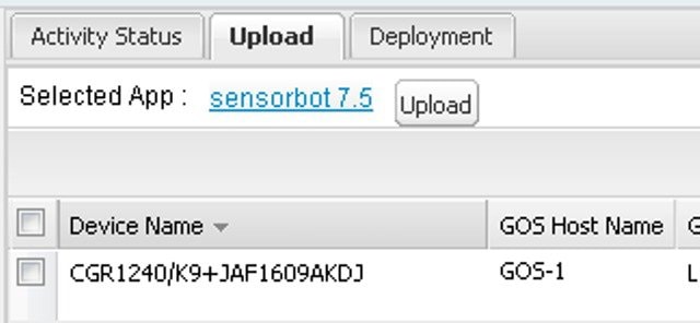
10.![]() Click the Upload button to upload the file to IoT FND.
Click the Upload button to upload the file to IoT FND.
The activity status (UPLOAD_OP_COMPLETE or UPLOAD_OP_WAITING) displays on the Upload tab.
Deploying GOS Apps
The Config > App Management Deployment tab allows you to perform the following activities on selected CGRs and IR800s:
■![]() Set to Run – A combination of install and start operations.
Set to Run – A combination of install and start operations.
■![]() Install – Installs the remote package and extracts the app.
Install – Installs the remote package and extracts the app.
■![]() Start and Stop – Starts or stops the app.
Start and Stop – Starts or stops the app.
■![]() Uninstall – Uninstalls the app.
Uninstall – Uninstalls the app.
■![]() Delete Remote Package – Deletes the previous upload package from the repository.
Delete Remote Package – Deletes the previous upload package from the repository.
To deploy GOS apps on selected CGRs:
1.![]() On the Config > Apps Management page, select a firmware or configuration group in the left pane.
On the Config > Apps Management page, select a firmware or configuration group in the left pane.
3.![]() In the Select an Action drop-down menu, choose the desired action to perform on the selected group.
In the Select an Action drop-down menu, choose the desired action to perform on the selected group.
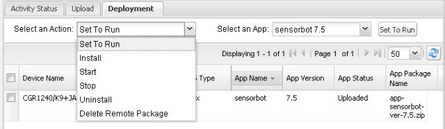
The action button at the right reflects your selected action (that is, if you select Install as the action, the action button label is “Install.”
4.![]() In the Select an App drop-down menu, choose an app or select all apps.
In the Select an App drop-down menu, choose an app or select all apps.
The activity begins. You can monitor activity progress on the Activity Status tab.
Deleting GOS Apps
To delete an app from the NMS server, on the Config > Apps Management page:
1.![]() Select a firmware or configuration group in the left pane.
Select a firmware or configuration group in the left pane.
3.![]() Click Select an App or click the Import Apps button in the left pane.
Click Select an App or click the Import Apps button in the left pane.
The Import Apps dialog box displays apps already uploaded to the NMS server.
4.![]() In the App Name list, scroll to the right and click the Delete link in the row with the app to delete from the NMS server.
In the App Name list, scroll to the right and click the Delete link in the row with the app to delete from the NMS server.
Restarting a Guest OS
To restart a GOS, on the Config > Device Configuration page:
1.![]() In the CONFIGURATION GROUPS pane, select the device with the GOS to restart.
In the CONFIGURATION GROUPS pane, select the device with the GOS to restart.
3.![]() Click the Restart button (Config > Device Configuration Page – Guest OS Tab Restart Button).
Click the Restart button (Config > Device Configuration Page – Guest OS Tab Restart Button).
Figure 7 Config > Device Configuration Page – Guest OS Tab Restart Button
Pushing GOS Configurations
You can push the GOS configuration to the CGR using the IoT FND config template. This is the only way to configure the DHCP pool.
Managing Files
Use the Config > Router File Management page to transfer and execute dual backhaul and Embedded Event Manager (EEM) scripts on the FAR. The Template module performs file validation. This section includes the following topics:
Note: File management is role-dependent and may not be available to all users. See Managing Roles.
File Types and Attributes
Two types of EEM scripts are used on the FAR: an embedded applet, and Tool Command Language (TCL) scripts that execute on the FAR individually. You can upload and run new EEM TCL scripts on the FAR without doing a firmware upgrade. EEM files upload to the eem directory in FAR flash memory. These scripts display in the Import File page File Type column as eem script. You must edit the configuration template file to activate the EEM TCL scripts (see Editing the ROUTER Configuration Template). This feature works with all FAR OS versions currently supported by IoT FND.
You can also transfer other file types to the FAR for better file management capability. You must first import the files to IoT FND to upload files to the FAR. IoT FND processes the file and stores it in the IoT FND database with the following attributes:
Adding a File to IoT FND
1.![]() On the Config > Router File Management page, click Import Files or Upload to open the Select File from List dialog box.
On the Config > Router File Management page, click Import Files or Upload to open the Select File from List dialog box.
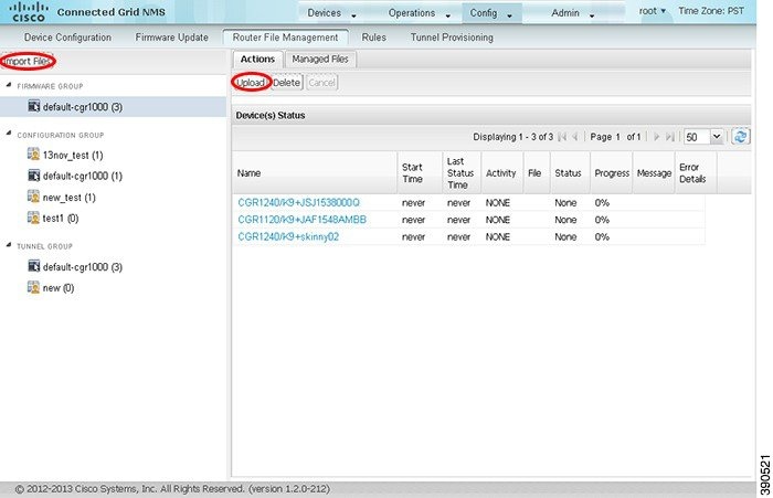
2.![]() Click Add File and browse to the file location.
Click Add File and browse to the file location.
Note: The maximum import file size is 200 MB.

Note: In the Select File from List![]() dialog box, you can also delete imported files from the IoT FND database if the file is not in an active file transfer. This only removes the file from the IoT FND database, not from any FARs that contain the file. Click the Name hyperlink to view uploaded text files (file size must be less than 100KB).
dialog box, you can also delete imported files from the IoT FND database if the file is not in an active file transfer. This only removes the file from the IoT FND database, not from any FARs that contain the file. Click the Name hyperlink to view uploaded text files (file size must be less than 100KB).
3.![]() (Optional) Type a description for the file.
(Optional) Type a description for the file.
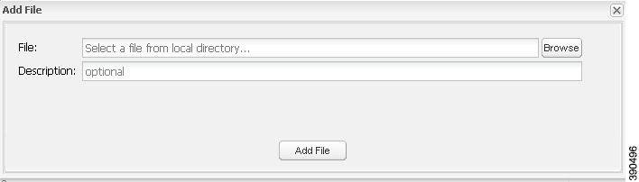
When the upload completes, the file name displays in the Select File From List dialog box.
5.![]() Repeat steps 2 through 4 to add another file, or see Transferring Files to upload the file to the selected device or group, or close the Select File From List dialog box.
Repeat steps 2 through 4 to add another file, or see Transferring Files to upload the file to the selected device or group, or close the Select File From List dialog box.
Transferring Files
You can transfer files from the NMS database to any firmware, configuration or tunnel provisioning group, or to individual FARs. The maximum import file size is 200 MB.
1.![]() On the Config > Router File Management page, select the group to transfer the file to in the Browse Devices pane.
On the Config > Router File Management page, select the group to transfer the file to in the Browse Devices pane.
2.![]() Click Import Files or Upload on the Actions tab.
Click Import Files or Upload on the Actions tab.
The Select File from List dialog box displays.
3.![]() Select the file to transfer to the FARs in the selected group.
Select the file to transfer to the FARs in the selected group.
The Upload File to Routers dialog box displays.
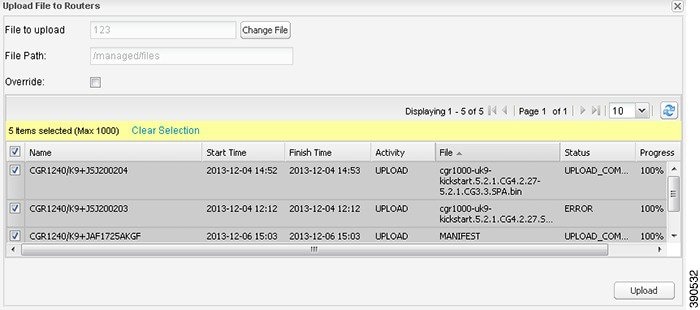
5.![]() Check the check boxes of the FARs to which you want to transfer the file.
Check the check boxes of the FARs to which you want to transfer the file.
If there is no file transfer or deletion, configuration push, firmware upload, or install or reprovision operations in progress for the group, the upload starts.
You can choose to transfer files to all FARs in the selected group or select only a subset of the FARs in the group. You can also select another group and file to perform a separate file transfer or deletion simultaneously.
All files transferred from IoT FND reside on the FAR in flash:/managed/files/ for Cisco IOS CGRs, and bootflash:/managed/files/ for CG-OS CGRs.
The status of the last file transfer is saved with the group, as well as the operation (firmware update, configuration push, and so on) and status of the group.
Viewing Files
To view imported text file content:
1.![]() Click the EID link to display the Device Info pane.
Click the EID link to display the Device Info pane.
2.![]() Click the Router Files tab.
Click the Router Files tab.
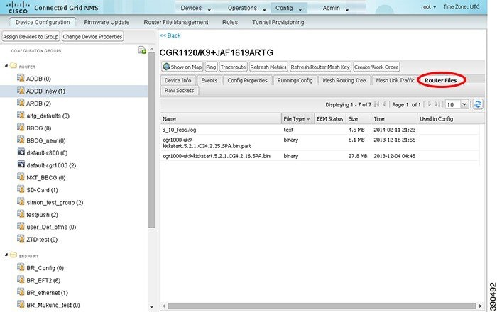
3.![]() Click the file name link to view the content in a new window.
Click the file name link to view the content in a new window.
Note: IoT FND only displays files saved as plain text that are under 100 KB are viewable. You cannot view larger text files or binary files of any size. Those file types do not have a hyperlink.
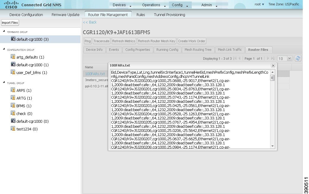
Monitoring Files
On the Config > Router File Management page, click the Managed Files tab to view a list of FARs and the files uploaded to their.../managed/files/ directories. Devices listed in the main pane are members of the selected group.
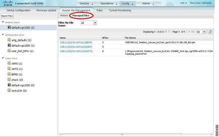
The following information is included in this list:
■![]() EID link to the Device Info page
EID link to the Device Info page
■![]() Number of files stored on the device
Number of files stored on the device
You can use the Filter By File Name drop-down menu to only view devices that contain a particular file. Select All to include all devices in the group. Click the refresh button to update the list during file transfer or deletion processes.
Monitoring Actions
On the Config > Router File Management page, click the Actions tab to view the status of the last file transfer or last file deleted for FARs in the selected group. You can click the Cancel button to terminate any active file operation.
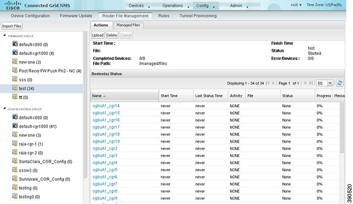
The Actions tab lists the following attributes:
■![]() Start date and time of the last transfer
Start date and time of the last transfer
■![]() End date and time of the last transfer
End date and time of the last transfer
■![]() Status of the process: UNKNOWN, AWAITING_DELETE, DELETE_IN_PROGRESS, DELETE_COMPLETE, CANCELLED, NOTSTARTED, UPLOAD_IN_PROGRESS, UPLOAD_COMPLETE, STOPPING, STOPPED
Status of the process: UNKNOWN, AWAITING_DELETE, DELETE_IN_PROGRESS, DELETE_COMPLETE, CANCELLED, NOTSTARTED, UPLOAD_IN_PROGRESS, UPLOAD_COMPLETE, STOPPING, STOPPED
■![]() Number of devices with upload complete and total number of target devices
Number of devices with upload complete and total number of target devices
■![]() Number of errors and errored device count
Number of errors and errored device count
■![]() Activity performed: UPLOAD, DELETE, NONE
Activity performed: UPLOAD, DELETE, NONE
■![]() Messages regarding any issues discovered during the process
Messages regarding any issues discovered during the process
Deleting Files
1.![]() On the Config > Router File Management page, select the group to transfer the file to in the Browse Devices pane.
On the Config > Router File Management page, select the group to transfer the file to in the Browse Devices pane.
2.![]() On the Actions tab, click Delete.
On the Actions tab, click Delete.
3.![]() In the Delete file from List dialog, select a file to delete.
In the Delete file from List dialog, select a file to delete.
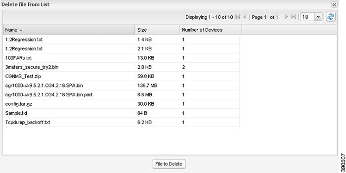
You can delete the file from all FARs in the selected group or any subset of FARs in the group.
The Delete File from Routers dialog box displays.
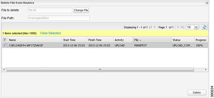
5.![]() Check the check boxes of the FARs from which you want to delete the file.
Check the check boxes of the FARs from which you want to delete the file.
| ■ |
If there are no file transfer or deletion, configuration push, firmware upload, or install or reprovision operations in progress for the group, the delete operation begins. IoT FND searches the.../managed/files/ directory on the devices for the specified file name.
Note: On deletion, all file content is purged from the selected devices, but not from the IoT FND database. File clean-up status displays for the selected group.
You can select another group and file to perform a separate file deletion while file transfer or deletion processes are in progress for this group. When you cancel file deletion processes before they complete, the currently running file deletion process completes and all waiting file deletion processes are canceled.
Managing Work Orders
■![]() Creating User Accounts for Device Manager (IoT-DM) Users
Creating User Accounts for Device Manager (IoT-DM) Users
Note: The Work Orders feature works with Release 3.0 or later of IoT-DM. For integration instructions, see “Accessing Work Authorizations” in the Cisco Connected Grid Device Manager Installation and User Guide, Release 3.1, or “Managing Work Orders” in the Cisco Connected Grid Device Manager Installation and User Guide (Cisco IOS), Release 4.0 and 4.1 or Cisco IoT Device Manager Installation and User Guide (Cisco IOS), Release 5.0.
Note: If you are using CGDM Release 3.1 and later, you must enable SSLv3 for IoT-DM–IoT FND connection authentication:
2.![]() For IoT-DM Release 3.x and later, in the following files, replace protocol="TLSv1" attribute:
For IoT-DM Release 3.x and later, in the following files, replace protocol="TLSv1" attribute:
Viewing Work Orders
To view work orders in IoT FND, choose Operations > Work Orders.
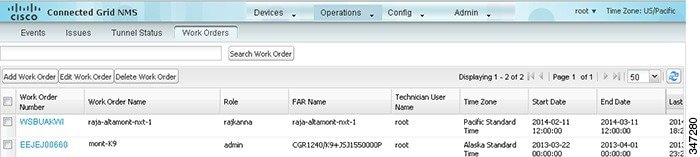
Work Orders Page Fields lists fields that display on the Work Orders page.
Searching Work Orders
To refine your search, use the following syntax in the Search Work Order field (Operations > Work Orders):
For example, to search for completed work orders that have a user with an admin role assigned to them, use this syntax:
role:admin workOrderStatus:Completed
To search work orders in IoT FND:
1.![]() Choose Operations > Work Orders.
Choose Operations > Work Orders.
2.![]() In the Search Work Order field, enter the search syntax and click Search Work Orders.
In the Search Work Order field, enter the search syntax and click Search Work Orders.
Creating User Accounts for Device Manager (IoT-DM) Users
Before creating work orders, you must create user accounts for the field technicians who use IoT-DM to download work orders from IoT FND.
To create a Device Manager user account:
1.![]() If not defined, create a Device Manager User role:
If not defined, create a Device Manager User role:
a.![]() Choose Admin > Access Management > Roles.
Choose Admin > Access Management > Roles.
c.![]() (CG-OS only)) In the Role Name field, enter a name for the role.
(CG-OS only)) In the Role Name field, enter a name for the role.
d.![]() Check the check box for Device Manager User, and then click Save.
Check the check box for Device Manager User, and then click Save.
a.![]() Choose Admin > Access Management > Users, and then click Add.
Choose Admin > Access Management > Users, and then click Add.
b.![]() Configure the user name, password, and time zone information.
Configure the user name, password, and time zone information.
c.![]() Check the check boxes for Monitor Only and the Device Manager User role you created in Step 1.
Check the check boxes for Monitor Only and the Device Manager User role you created in Step 1.
Creating Work Orders
If you need a technician to inspect a deployed FAR (CGR 1120 or CGR 1240) or DA Gateway (IR509) in the field, create a work order. A work order includes the WiFi credentials required for the technician to connect to the router.
■![]() Your user account must have the Work Order Management permissions enabled.
Your user account must have the Work Order Management permissions enabled.
■![]() To provide a signed work order to IoT-DM on request, you must import IoT-DM certificates to cgms_keystore using the alias cgms.
To provide a signed work order to IoT-DM on request, you must import IoT-DM certificates to cgms_keystore using the alias cgms.
■![]() Create the user account for the field technician. (See Creating User Accounts for Device Manager (IoT-DM) Users)
Create the user account for the field technician. (See Creating User Accounts for Device Manager (IoT-DM) Users)
Note: You can only create work orders for CGRs and IR509 devices.
To create a work order for FARs or DA Gateways:
1.![]() Choose Operations > Work Orders.
Choose Operations > Work Orders.
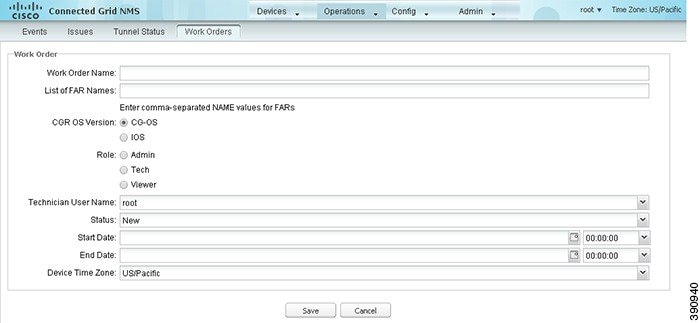
3.![]() In the Work Order Name field, enter the name of the work order.
In the Work Order Name field, enter the name of the work order.
4.![]() In the Field Device Names/EIDs field, enter a comma-separated list of FAR names or EIDs.
In the Field Device Names/EIDs field, enter a comma-separated list of FAR names or EIDs.
For every FAR in the list, IoT FND creates a work order (one work order per FAR).
5.![]() In the Device User Name field, enter the IoT-DM name of the technician.
In the Device User Name field, enter the IoT-DM name of the technician.
6.![]() In the Device Type field, select Router or Endpoint.
In the Device Type field, select Router or Endpoint.
7.![]() Click the radio button of the operating system type for the CGR: CG-OS or IOS.
Click the radio button of the operating system type for the CGR: CG-OS or IOS.
9.![]() From the Technician User Name drop-down menu, choose their IoT FND user name.
From the Technician User Name drop-down menu, choose their IoT FND user name.
This menu only lists users with IoT-DM User permissions enabled.
10.![]() From the Status drop-down menu, choose the status of the work order (New, Assigned, In Service, Completed, or InComplete).
From the Status drop-down menu, choose the status of the work order (New, Assigned, In Service, Completed, or InComplete).
Note: For a IoT-DM user to retrieve a work order, the work order must be in the Assigned state in IoT FND for that user. If the work order is in any other state, IoT-DM cannot retrieve the signed work order.
Note: After the work order has been successfully requested by the IoT-DM user, the state of work order changes to In Service.
11.![]() In the Start Date and End Date fields, specify the starting and ending dates for which the work order is valid.
In the Start Date and End Date fields, specify the starting and ending dates for which the work order is valid.
If the work order is not valid, the technician cannot access the router.
12.![]() In the Device Time Zone field, choose the time zone of the device from the drop-down menu.
In the Device Time Zone field, choose the time zone of the device from the drop-down menu.
You can also create work orders on the Field Devices page (Devices > Field Devices), as described in Creating Work Orders, and on the Device Info page.
Downloading Work Orders
To download the work orders created by IoT FND, field technicians use Cisco IoT-DM, a Windows-based application that field technicians use to manage a single Cisco CGR 1000 router. The technician can download all work orders in the Assigned state.
Field technicians use IoT-DM to update work order status, which is sent to IoT FND.
Note: Certificates are not included in the work order and are preinstalled on the IoT-DM field laptop prior to downloading work orders from IoT FND.
For more information about IoT-DM, see the Cisco IoT Device Manager User Guide.
Editing Work Orders
1.![]() Choose Operations > Work Orders.
Choose Operations > Work Orders.
2.![]() Select the work order to edit, and then click Edit Work Order.
Select the work order to edit, and then click Edit Work Order.
Alternatively, click the work order number to open the page displaying the work order details.
Deleting Work Orders
1.![]() Choose Operations > Work Orders.
Choose Operations > Work Orders.
Device Properties
This section describes the device properties that you can view in IoT FND. Some of these properties are configurable; others are not.
■![]() Device Properties by Category
Device Properties by Category
Types of Device Properties
IoT FND stores two types of device properties in its database:
■![]() Actual device properties—These are the properties defined by the device, such as IP Address, Transmit Speed, and SSID.
Actual device properties—These are the properties defined by the device, such as IP Address, Transmit Speed, and SSID.
■![]() IoT FND device properties—These are properties defined by IoT FND for devices, such Latitude and Longitude properties, which IoT FND uses to display device locations on its GIS map.
IoT FND device properties—These are properties defined by IoT FND for devices, such Latitude and Longitude properties, which IoT FND uses to display device locations on its GIS map.
Note: The Key column provides the version of the property name in the IoT FND database that you can use in filters. For example, to search for the device with an IP address of 10.33.0.30, enter ip:10.33.0.30 in the Search Devices field.
Device Properties by Category
This section presents IoT FND device properties by category:
■![]() Embedded Access Point Credentials
Embedded Access Point Credentials
■![]() Head-End Routers > Netconf Config
Head-End Routers > Netconf Config
■![]() Head-End Routers > Tunnel 1 Config
Head-End Routers > Tunnel 1 Config
■![]() Head-End Routers > Tunnel 2 Config
Head-End Routers > Tunnel 2 Config
■![]() Raw Sockets Metrics and Sessions
Raw Sockets Metrics and Sessions
Every device in IoT FND presents a list of fields, which are used for device searches. The available fields for a device are defined in the Device Type field. Fields are either configurable or discovered. Configurable fields are set using XML and CSV files; the device EID is the lookup key. Discovered fields are presented from the device. Fields are also accessible in the device configuration templates for FARs.
Cellular Link Settings
Cellular Link Settings Area Fields lists the fields in the Cellular Link area of the Device Info view.
Cellular Link Metrics
Cellular Link Metrics Area Fields describes the fields in the Cellular Link Metrics area of the Device Info view.
DA Gateway Properties
DA Gateway Metrics Area Fields describes the fields in the DA Gateway area of the Device Info view.
Dual PHY WPAN Properties
Dual PHY Metrics Area Fields describes the fields in the Dual PHY area of the Device Info view.
Embedded Access Point Credentials
Embedded Access Point Credentials Fields describes the fields in the Embedded Access Point Credentials area of the Device Info view.
|
|
|
|
|
|---|---|---|---|
Embedded AP Properties
Embedded AP Properties describes the fields on the Embedded AP tab of the C800 or IR800 Device Info view.
|
|
|
|
|---|---|---|
Ethernet Link Metrics
Ethernet Link Metrics Area Fields describes the fields in the Ethernet link traffic area of the Device Info view.
Guest OS Properties
Guest OS Properties Fields describes the fields in the Guest OS Properties area of the Config Properties page.
|
|
|
|
|---|---|---|
Head-End Routers > Netconf Config
Head-End Routers > Netconf Config Client Fields describes the fields in the Netconf Client area of the Head-End Routers > Config Properties page.
Head-End Routers > Tunnel 1 Config
Head-End Routers > Tunnel 1 Config Fields describes the fields in the Tunnel 1 Config area of the Head-End Routers > Config Properties page.
Head-End Routers > Tunnel 2 Config
Head-End Routers > Tunnel 2 Config Device Fields describes the fields in the Tunnel 2 Config area of the Head-End Routers > Config Properties page.
Inventory
Inventory Fields describes the fields in the Inventory area of the Device Info page.
Mesh Link Config
Mesh Link Config Fields describes the fields in the Mesh Link Config area of the Routers > Config Properties page.
|
|
|
|
|
|---|---|---|---|
(Dual-PHY CGRs only) The interface on which the device is master. |
|||
(Dual-PHY CGRs only) The interface on which the device is slave. |
Mesh Device Health
Mesh Device Health Fields describes the fields in the Mesh Device Health area of the Device Info view.
|
|
|
|
|---|---|---|
The amount of time, in seconds, that the element has been running since last boot. |
Mesh Link Keys
Mesh Link Keys Fields describes the fields in the Mesh Link Keys area of the Device Info view.
|
|
|
|
|
|---|---|---|---|
Mesh Link Settings
Mesh Link Settings Fields describes the fields in the Mesh Link Settings area of the Device Info view.
Mesh Link Metrics
Mesh Link Metrics Fields describes the fields in the Mesh Link Metrics area of the Device Info page.
NAT44 Metrics
NAT44 Metrics Fields describes the fields in the NAT44 area of the Device Info page.
|
|
|
|
|---|---|---|
PLC Mesh Info
PLC Mesh Info Fields describes the fields in the PLC Mesh Info area of the Device Info view.
Raw Sockets Metrics and Sessions
Raw Sockets Metrics and Sessions View describes the fields in the TCP Raw Sockets area of the Field Devices > Config Properties page.
Router Battery
Router Battery Device View describes the fields in the Router Battery area of the Device Info page.
Router Config
Router Config Device View describes the fields in the Router Config area of the Field Devices > Config Properties page.
|
|
|
|
|
|---|---|---|---|
The internal GPS module provides the router location (longitude and latitude). |
Router Credentials
Router Credentials Fields describes the fields in the Router Credentials area of the Field Devices > Config Properties page.
|
|
|
|
|
|---|---|---|---|
Router DHCP Info
Router DHCP Fields describes the fields in the DHCP Info area of the Device Info page.
|
|
|
|
|---|---|---|
Router DHCP Proxy Config
DHCP Proxy Config Fields describes the fields in the DHCP Proxy Config area of the Field Devices > Config Properties page.
Router Health
Router Health Device View describes the Router Health fields in the Device Info view.
Router Tunnel Config
Router Tunnel Config Device View describes the fields in the Router Tunnel Config area of the Field Devices > Config Properties page.
|
|
|
|
|
|---|---|---|---|
Displays the EID number of the HER that the FAR connects with through secure tunnels. |
|||
Displays the Non-Broadcast Multiple Access (NBMA) IPv4 address. |
|||
Router Tunnel 1 Config
Router Tunnel 1 Config Device View describes the fields in the Router Tunnel 1 Config area of the Field Devices > Config Properties page.
Router Tunnel 2 Config
Router Tunnel 2 Config Device View describes the fields in the Router Tunnel 2 Config area of the Field Devices > Config Properties page.
SCADA Metrics
SCADA Metrics View describes the fields on the SCADA tab of the Device Info page.
User-defined Properties
The User-defined Properties area of the Routers > Config Properties page displays any customer defined properties.
WiFi Interface Config
WiFi Interface Config Fields describes the fields in the WiFi Interface Config area of the Field Devices > Config Properties page.
|
|
|
|
|
|---|---|---|---|
The service set identifier (SSID) assigned to the WiFi interface on the FAR. |
|||
The key used to encrypt other pre-shared keys stored on the FAR. |
WiMAX Config
WiMAX Config Fields describes the fields in the WiMAX Config area of the Device Info page.
|
|
|
|
|---|---|---|
WiMAX Link Metrics
WiMAX Link Health Fields describes the fields in the WiMAX Link Health area of the Device Info page.
WiMAX Link Settings
WiMAX Link Settings Fields describes the fields in the WiMAX Link Settings area of the Device Info page.
|
|
|
|
|---|---|---|
 Feedback