- Unpacking the Router
- Site Preparation and Installation Safety (Read before Installing)
- Hardware Features - Description and Specifications
- Mounting and Grounding the Router
- Opening and Closing the Router Chassis
- Making Network, Power, and Other Connections
- Powering Off the Router
- Unmounting the Router
- Installing Connected Grid Modules
- Antennas
- About the SD Flash Memory Module
- Installing Battery Backup Units (BBUs)
- Installing External, Non-Cisco Radio Modules
- LED Locations and States
- Appendix - Starting a Router Terminal or Console Session
- Appendix - Cable and Connector Specifications
- Mounting Kits Overview
- General Safety Information for Mounting
- Contents of the Mounting Kits
- Materials and Tools You Supply
- Mounting Instructions
- Simple Mounting Bracket for Pole Mounting of CGR1240
- Grounding Instructions
- Bracket Dimensions
Mounting the Router
This section describes the safety information, equipment, and procedures required to mount the Cisco 1240 Connected Grid Router (CGR 1240 or router) on a vertical pole or streetlight.
■![]() General Safety Information for Mounting
General Safety Information for Mounting
■![]() Contents of the Mounting Kits
Contents of the Mounting Kits
■![]() Materials and Tools You Supply
Materials and Tools You Supply
■![]() Simple Mounting Bracket for Pole Mounting of CGR1240
Simple Mounting Bracket for Pole Mounting of CGR1240
Mounting Kits Overview
You will need some or all of the kits described in this section to install the router on a pole. Your installation environment and requirements determine the kits you need.
For a detailed description of each kit, see Contents of the Mounting Kits.
|
|
|
|
|---|---|---|
Use this kit if your installation requires a Cisco mounting bracket to mount the router. This kit is included within the router accessory kit, and is used with the pole kit and includes the hardware required to attach the mounting bracket to the mounting plate. |
||
This kit is required for all pole or streetlight installations and includes a mounting plate and the hardware required to attach the mounting plate to a pole. |
||
This kit includes two steel straps for mounting the router on poles larger than 4.5 inches (11.4 cm) in diameter. This kit is used together with the Pole Mount Kit. A BAND-IT Tool is required to install the steel straps on a pole. |
||
This kit includes a BAND-IT tool that is required when using steel straps to install the router on poles larger than 4.5 inches (11.4 cm) in diameter. |
General Safety Information for Mounting
Read the safety warnings in this section and in Installation Safety and Site Preparation.
One person is required to properly and safely mount the router.
Caution: All mounting methods at any location are subject to the acceptance of local jurisdiction.
Caution: The mounting surface, attaching screws, and optional wall anchors must be able to support a 50 pound (22.7 kg) static weight.
Caution: Personnel mounting the router must understand grounding methods.
Warning: Do not locate the antenna near overhead power lines or other electric light or power circuits, or where it can come into contact with such circuits. When installing the antenna, take extreme care not to come into contact with such circuits, as they may cause serious injury or death. For proper installation and grounding of the antenna, please refer to national and local codes (for example, U.S.:NFPA 70, National Electrical Code, Article 810, Canada: Canadian Electrical Code, Section 54). Statement 1052
Contents of the Mounting Kits
This section describes the contents of the mounting kits available for the router and when you should use each kit.
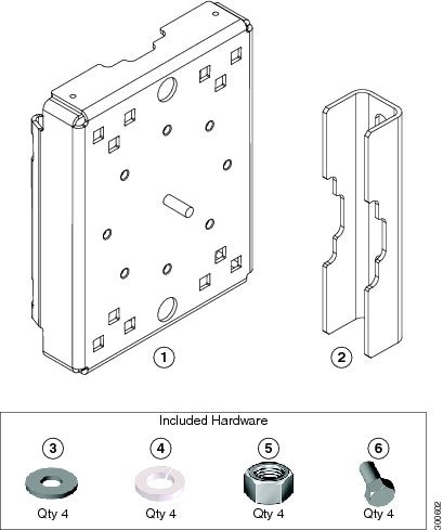
Pole Mount Kit
Use the Cisco pole mount kit to install the mounting plate on any pole or streetlight. The kit supports poles that meet the following criteria:
■![]() Size —2 to 16 inch diameter poles
Size —2 to 16 inch diameter poles
■![]() Material —Metal, wood, or fiberglass poles
Material —Metal, wood, or fiberglass poles
Figure 23 Pole Mount Kit Contents
|
|
|
|
|
|---|---|---|---|
|
|
Install mounting plate on pole. Mounting bracket attaches to mounting plate. |
||
|
|
Use the clamp brackets to install the mounting plate on a pole. |
||
|
|
|||
|
|
Use the included hardware to attach the mounting plate to the pole, as described in Install the Mounting Plate onto a Pole. |
||
|
|
|||
|
|
|||
|
|
|||
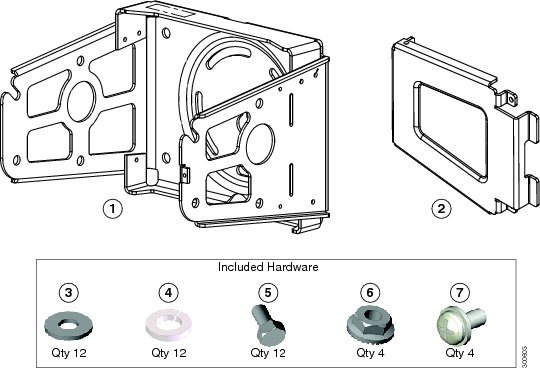
Mounting Bracket Kit
Use the mounting bracket kit if you require a Cisco mounting bracket. The mounting bracket attaches to the mounting plate, and then the router is installed on the mounting bracket.
Note: You can optionally use any compatible mounting bracket with the Cisco pole mount kit. Check with your authorized Cisco reseller for compatible mounting brackets. See Pole Mount Kit
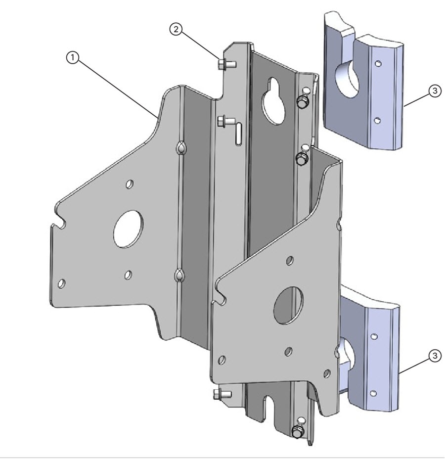
Figure 24 Mounting Bracket Kit Contents—Required Parts
|
|
|
|
|
|---|---|---|---|
|
|
Mounts router to mounting plate, which is installed on pole. |
||
|
|
Optional bracket feature, which prevents the unauthorized users from removing the router from the mounting bracket. |
||
|
|
|||
|
|
Use this hardware to attach the mounting bracket to the mounting plate, and the router to the mounting bracket. Assemble the washer, split lock washer, and bolt as described in Assemble Bracket Hardware. |
||
|
|
|||
|
|
|||
|
|
|||
|
|
Use these screws to attach the security panel to the mounting bracket. |
||
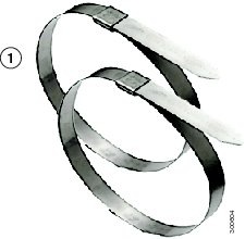
Band Strap Kit
Use the straps in the Band Strap Kit when you mount the router on a pole larger than 4.5 inches (11.4 cm) in diameter. This installation also requires the pole mount kit and strap tool kit. See Pole Mount Kit and Strap Tool Kit.
Figure 25 Band Strap Kit Contents
|
|
|
|---|---|
|
|
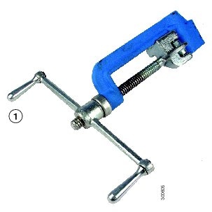
Strap Tool Kit
Use the tool in the Strap Tool Kit to attach the steel straps included in the band strap kit. Steel straps are required to install the mounting plate on poles larger than 4.5 inches (11.4 cm) in diameter. See Band Strap Kit.
Note: The tool in the Strap Tool Kit is manufactured and supported by BAND-IT. For more information about the tool, see www.band-it-idex.com.
Figure 26 Strap Tool Kit Contents
|
|
|
|---|---|
|
|
|
|
|
Materials and Tools You Supply
You must supply some or all of these items to mount the router on a pole. The items you supply depends on the installation procedure that you use.
|
|
|
|---|---|
Install the Mounting Plate—Poles Up to 4.5 Inches in Diameter |
|
Bolt, standard washer, fender washer, and nut, 5/8 inch (2 sets)—Bolt length depends on the size of the pole used in the installation. |
|
Phillips screwdriver, or other screwdriver for cross-recessed screws |
|
Mounting Instructions
This section includes all the procedures required to mount the router on any supported pole type.
This section covers the following procedures:
■![]() Install the Mounting Plate onto a Pole
Install the Mounting Plate onto a Pole
■![]() Attach the Mounting Bracket to the Mounting Plate
Attach the Mounting Bracket to the Mounting Plate
■![]() Install the Router onto the Mounting Bracket
Install the Router onto the Mounting Bracket
■![]() Mounting the Router onto a Wall
Mounting the Router onto a Wall
Router Orientation
When mounting the router on a pole, ensure that:
■![]() The router is oriented with the chassis cabling openings pointing down so the router cables can be correctly connected through the openings and so the router door opens correctly, as shown in Figure 35.
The router is oriented with the chassis cabling openings pointing down so the router cables can be correctly connected through the openings and so the router door opens correctly, as shown in Figure 35.
■![]() The router is mounted with the hinged access cover facing out.
The router is mounted with the hinged access cover facing out.
Install the Mounting Plate onto a Pole
This section describes three different procedures for installing the mounting plate on a pole. Follow the instructions for the pole type used in your installation.
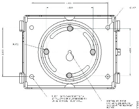
The instructions in these section refer to the mounting plate features shown in Figure 27.
■![]() Install the Mounting Plate—Poles Up to 4.5 Inches in Diameter
Install the Mounting Plate—Poles Up to 4.5 Inches in Diameter
■![]() Install the Mounting Plate—Poles Larger than 4.5 Inches in Diameter
Install the Mounting Plate—Poles Larger than 4.5 Inches in Diameter
■![]() Install the Mounting Plate—Through-Pole Mounting (Optional)
Install the Mounting Plate—Through-Pole Mounting (Optional)
Figure 27 Mounting Plate Details
|
|
|
|
|---|---|---|
|
|
||
|
|
||
|
|
||
|
|
||
|
|
Install the Mounting Plate—Poles Up to 4.5 Inches in Diameter
■![]() Mounting plate, carriage bolts, and clamp brackets included in Pole Mount Kit.
Mounting plate, carriage bolts, and clamp brackets included in Pole Mount Kit.
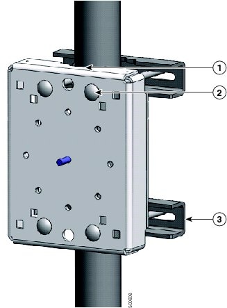
To install the mounting plate on a vertical pole up to 4.5 inches (11.4 cm) in diameter (refer to Figure 28 and Figure 29:
1.![]() Select a mounting location on the pole and place the top and bottom pole clamp bracket (1) notches against the pole.
Select a mounting location on the pole and place the top and bottom pole clamp bracket (1) notches against the pole.
2.![]() Place one of the clamp brackets on the opposite side of the pole, aligning the clamp bracket holes with the top two carriage bolt holes on the mounting plate.
Place one of the clamp brackets on the opposite side of the pole, aligning the clamp bracket holes with the top two carriage bolt holes on the mounting plate.
3.![]() Insert a carriage bolt ( 5) through each of the top two carriage bolt holes on the mounting plate and through the holes in the clamp brackets.
Insert a carriage bolt ( 5) through each of the top two carriage bolt holes on the mounting plate and through the holes in the clamp brackets.
4.![]() Position the each bolt in the clamp so that the bolt is next to the pole, as shown in Figure 28.
Position the each bolt in the clamp so that the bolt is next to the pole, as shown in Figure 28.
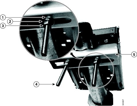
5.![]() To place the bracket hardware on each carriage bolt (see Figure 28):
To place the bracket hardware on each carriage bolt (see Figure 28):
a.![]() Place the washer ( 2) and then the split lock washer ( 3) on the back of each carriage bolt ( 5).
Place the washer ( 2) and then the split lock washer ( 3) on the back of each carriage bolt ( 5).
b.![]() Thread the hex nut ( 4) on each carriage bolt. Place the split-lock washer between the washer and the nut.
Thread the hex nut ( 4) on each carriage bolt. Place the split-lock washer between the washer and the nut.
Figure 28 Carriage Bolt Hardware Assembly Details
6.![]() Hand tighten the hex nuts (do not overtighten).
Hand tighten the hex nuts (do not overtighten).
7.![]() Repeat Step 3 through Step 6, installing the two bottom carriage bolts and the second clamp bracket at the bottom of the mounting plate.
Repeat Step 3 through Step 6, installing the two bottom carriage bolts and the second clamp bracket at the bottom of the mounting plate.
8.![]() Position the mounting plate and clamp brackets on the pole as needed before further tightening the carriage bolts.
Position the mounting plate and clamp brackets on the pole as needed before further tightening the carriage bolts.
9.![]() Use a socket wrench to evenly tighten all four carriage bolts to finish installing the mounting plate on the pole.
Use a socket wrench to evenly tighten all four carriage bolts to finish installing the mounting plate on the pole.
Figure 29 Mounting Plate Installed on Pole with Clamp Brackets
|
|
|
|---|---|
|
|
|
|
|
|
|
|
Install the Mounting Plate—Poles Larger than 4.5 Inches in Diameter
■![]() Mounting plate and steel straps included in Pole Mount Kit.
Mounting plate and steel straps included in Pole Mount Kit.
■![]() BAND-IT tool included in Strap Tool Kit
BAND-IT tool included in Strap Tool Kit
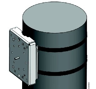
To install the mounting plate on a vertical pole that is larger than 4.5 inches (11.4 cm) in diameter (refer to Figure 30):
1.![]() Assemble the straps and the mounting plate by threading the two steel straps through the band strap slots on the mounting plate.
Assemble the straps and the mounting plate by threading the two steel straps through the band strap slots on the mounting plate.
2.![]() Select a mounting location on the pole.
Select a mounting location on the pole.
3.![]() Position the mounting plate on the pole as needed and tighten the straps around the pole.
Position the mounting plate on the pole as needed and tighten the straps around the pole.
4.![]() Use the BAND-IT strap tool to tighten the metal bands around the pole, following the instructions in the box with the tool. Ensure the metal bands are as tight as possible (approximately 7 ft-lbs).
Use the BAND-IT strap tool to tighten the metal bands around the pole, following the instructions in the box with the tool. Ensure the metal bands are as tight as possible (approximately 7 ft-lbs).
Note: When the metal bands are tightened to the full tension, the mounting plate cannot be adjusted unless the metal bands are disassembled or cut.
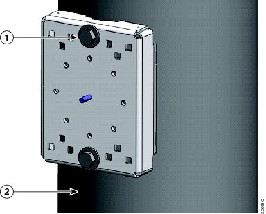
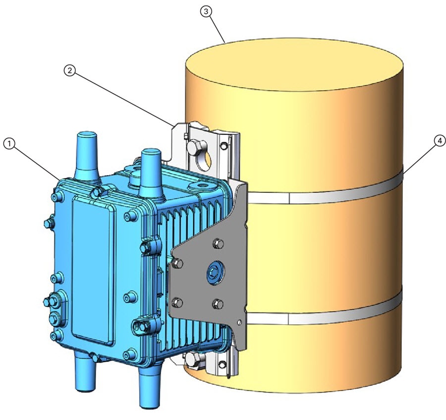
Figure 30 Mounting Plate Installed on Pole with Steel Straps
Install the Mounting Plate—Through-Pole Mounting (Optional)
If the pole used in your installation is made of wood, you can optionally install the mounting plate using the procedure described in this section. This is an alternate mounting method to the following two mounting methods, which can also be used when mounting the router on a wood pole:
■![]() Install the Mounting Plate—Poles Up to 4.5 Inches in Diameter
Install the Mounting Plate—Poles Up to 4.5 Inches in Diameter
■![]() Install the Mounting Plate—Poles Larger than 4.5 Inches in Diameter
Install the Mounting Plate—Poles Larger than 4.5 Inches in Diameter
■![]() Mounting plate included in Pole Mount Kit.
Mounting plate included in Pole Mount Kit.
■![]() Hardware that you supply: 5/8-in. carriage bolt (length depends on the pole size in your installation), standard washer, fender washer, nut (2 sets)
Hardware that you supply: 5/8-in. carriage bolt (length depends on the pole size in your installation), standard washer, fender washer, nut (2 sets)
■![]() Tools that you supply: Drill, drill bit (for 5/8-in. through bolts), and 13-mm box-end socket wrench
Tools that you supply: Drill, drill bit (for 5/8-in. through bolts), and 13-mm box-end socket wrench
To mount the router on a wood pole:
1.![]() Place the mounting plate on the selected mounting location on the pole.
Place the mounting plate on the selected mounting location on the pole.
2.![]() Mark the drilling locations on the pole through the clearance holes and remove the mounting plate.
Mark the drilling locations on the pole through the clearance holes and remove the mounting plate.
3.![]() Drill holes completely through the pole at the points you marked in Step 2.
Drill holes completely through the pole at the points you marked in Step 2.
4.![]() Position the mounting plate over the drilled holes. Align the clearance holes on the mounting plate with the drilled holes.
Position the mounting plate over the drilled holes. Align the clearance holes on the mounting plate with the drilled holes.
5.![]() Place a standard washer against one of the clearance holes on the mounting plate, then feed the bolt through the washer, clearance hole, and drilled hole. Push the bolt all the way through the pole. See Figure 27.
Place a standard washer against one of the clearance holes on the mounting plate, then feed the bolt through the washer, clearance hole, and drilled hole. Push the bolt all the way through the pole. See Figure 27.
6.![]() Follow these steps on the opposite side of the pole:
Follow these steps on the opposite side of the pole:
a.![]() Place a fender washer on the end of the bolt, and then a nut.
Place a fender washer on the end of the bolt, and then a nut.
7.![]() Repeat Step 5 and Step 6 for the second bolt.
Repeat Step 5 and Step 6 for the second bolt.
8.![]() Use a socket wrench to evenly tighten both bolts to finish installing the mounting plate on the wooden pole.
Use a socket wrench to evenly tighten both bolts to finish installing the mounting plate on the wooden pole.
Figure 31 Mounting Plate Installed on Wooden Pole with Through Bolts
|
|
|
|---|---|
|
|
|
|
|
Attach the Mounting Bracket to the Mounting Plate
This section describes how to attach the mounting bracket to the mounting plate.
Assemble Bracket Hardware
Several of the procedures in this section require you to assemble the bracket hardware before installing the bracket. A bracket hardware set consists of one bolt, one washer, one split lock washer, and one nut.
To assemble the bracket hardware:
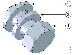
1.![]() Slide the split lock washer ( 2) on the bolt ( 1).
Slide the split lock washer ( 2) on the bolt ( 1).
2.![]() Slide the regular washer ( 3) on the bolt ( 1).
Slide the regular washer ( 3) on the bolt ( 1).
Place the split-lock washer between the regular washer and the bolt as shown in Figure 32.
Figure 32 Assemble Bracket Hardware Sets
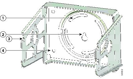
The instructions for the procedures in this section refer to the mounting plate features shown in Figure 33.
Figure 33 Mounting Bracket Details
|
|
|
|---|---|
|
|
|
|
|
|
|
|
|
|
|
Note: The mounting plate must be installed as described in Install the Mounting Plate onto a Pole.
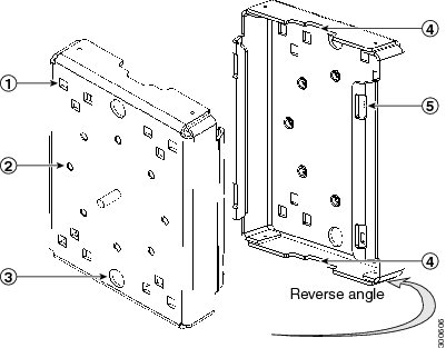
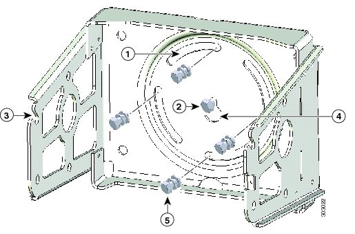
To attach the mounting bracket to the mounting plate (refer to Figure 34):
■![]() Mounting bracket and hardware included in the Mounting Bracket Kit
Mounting bracket and hardware included in the Mounting Bracket Kit
1.![]() Assemble four sets of bracket hardware (washer, split lock washer, and bolt) as shown in Assemble Bracket Hardware.
Assemble four sets of bracket hardware (washer, split lock washer, and bolt) as shown in Assemble Bracket Hardware.
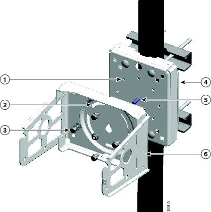
2.![]() Place the mounting bracket against the mounting plate by inserting the bracket quick hang notch over the mounting plate quick hang stud ( 4).
Place the mounting bracket against the mounting plate by inserting the bracket quick hang notch over the mounting plate quick hang stud ( 4).
3.![]() Thread the serrated nut onto the quick mount stud ( 4) and hand tighten (do not overtighten).
Thread the serrated nut onto the quick mount stud ( 4) and hand tighten (do not overtighten).
4.![]() Align the pivot grooves ( 2) on the bracket with four of the bracket mount holes ( 1) on the mounting plate. Follow these guidelines:
Align the pivot grooves ( 2) on the bracket with four of the bracket mount holes ( 1) on the mounting plate. Follow these guidelines:
–![]() Each of the four pivot grooves on the bracket must be attached to at least one bracket mount hole on the mounting plate.
Each of the four pivot grooves on the bracket must be attached to at least one bracket mount hole on the mounting plate.
–![]() The final desired orientation of the mounting plate and router determine which bracket mount holes are used.
The final desired orientation of the mounting plate and router determine which bracket mount holes are used.
–![]() Mount the router as described in Router Orientation.
Mount the router as described in Router Orientation.
5.![]() Insert one bolt assembly ( 3) through one of the pivot grooves ( 2) on the bracket and then through the corresponding bracket mount hole on the mounting plate.
Insert one bolt assembly ( 3) through one of the pivot grooves ( 2) on the bracket and then through the corresponding bracket mount hole on the mounting plate.
6.![]() Repeat Step 5 for the remaining bolt assemblies.
Repeat Step 5 for the remaining bolt assemblies.
7.![]() Position the mounting bracket onto the mounting plate as needed before further tightening the bolts.
Position the mounting bracket onto the mounting plate as needed before further tightening the bolts.
8.![]() Use a socket wrench to evenly tighten all four bolts and the serrated nut to finish installing the bracket on the plate. Use a torque of 6-7 foot-pounds when tightening the bolts and nut.
Use a socket wrench to evenly tighten all four bolts and the serrated nut to finish installing the bracket on the plate. Use a torque of 6-7 foot-pounds when tightening the bolts and nut.
Figure 34 Mounting Bracket Attached to Mounting Plate
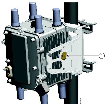
Install the Router onto the Mounting Bracket
This section describes how to attach the router to the mounting bracket. The mounting bracket is installed on the mounting plate (included in the Cisco pole mount kit), which is installed on a supported pole type. See Pole Mount Kit.
The instructions for the procedures in this section refer to the mounting bracket kit contents shown in Figure 24 and the bracket features described in Figure 33.
Note: Refer to Install the Optional Security Panel for how to install the optional security panel on the bracket.
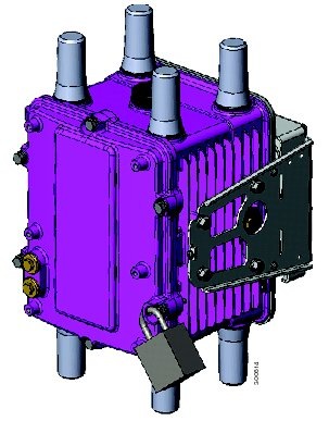
Figure 35 Router Installed in Mounting Bracket
■![]() Mounting bracket and hardware included in Mounting Bracket Kit.
Mounting bracket and hardware included in Mounting Bracket Kit.
■![]() Socket wrench that you supply.
Socket wrench that you supply.
To mount the router on the bracket (refer to Figure 36 and Figure 37:
1.![]() Assemble eight sets of bracket hardware (washer, split lock washer, and bolt) as shown in Assemble Bracket Hardware.
Assemble eight sets of bracket hardware (washer, split lock washer, and bolt) as shown in Assemble Bracket Hardware.
2.![]() Attach one set of hinge bolt hardware to the mounting bracket connector shown in Figure 37 ( 1).
Attach one set of hinge bolt hardware to the mounting bracket connector shown in Figure 37 ( 1).
Do not tighten the hardware until Step 6. There must be enough space between the washer and the router to slide the router onto the bracket.
3.![]() Repeat Step 2 on the other side of the router.
Repeat Step 2 on the other side of the router.
4.![]() Slide the router onto the bracket by inserting the hinge bolts you attached in Step 2 into the bracket quick hang slots ( 2).
Slide the router onto the bracket by inserting the hinge bolts you attached in Step 2 into the bracket quick hang slots ( 2).
Figure 36 Attach One Hinge Bolt to Each Side of the Router
5.![]() Attach the six remaining sets of hardware to each side of the bracket and router (3 sets on each side), as shown in Figure 37.
Attach the six remaining sets of hardware to each side of the bracket and router (3 sets on each side), as shown in Figure 37.
6.![]() Use a socket wrench to evenly tighten all four bolts, using 6-7 foot-pounds of torque.
Use a socket wrench to evenly tighten all four bolts, using 6-7 foot-pounds of torque.
Figure 37 Attach Remaining Bolts to Bracket and Router
Simple Mounting Bracket for Pole Mounting of CGR1240
■![]() Simple Mounting Bracket and hardware that is included in the kit (see Figure 38) which includes:
Simple Mounting Bracket and hardware that is included in the kit (see Figure 38) which includes:
1.![]() Attach the two (2) adapters to the bracket using 1/4 inch bolts as shown in Constructing the Mounting Bracket (CISCO-CGR-PM-BRKT). Be sure to attach the adapters to the brackets as illustrated.
Attach the two (2) adapters to the bracket using 1/4 inch bolts as shown in Constructing the Mounting Bracket (CISCO-CGR-PM-BRKT). Be sure to attach the adapters to the brackets as illustrated.
Figure 38 Constructing the Mounting Bracket (CISCO-CGR-PM-BRKT)
|
|
|
|---|---|
|
|
|
2.![]() Attach the Mounting Bracket to a pole (wooden or metal) by following the pole-specific instructions below:
Attach the Mounting Bracket to a pole (wooden or metal) by following the pole-specific instructions below:
–![]() To attach the bracket to a Wooden Pole, you will need to attach the bracket using two (2) 5/8 inch bolts specified for wooden poles. In addition, you can also use Band-it strips on the wooden poles, if desired.
To attach the bracket to a Wooden Pole, you will need to attach the bracket using two (2) 5/8 inch bolts specified for wooden poles. In addition, you can also use Band-it strips on the wooden poles, if desired.
–![]() To attach the bracket to a Metal Pole, use Band-it Straps as shown in Attach the CGR1240 Custom, Simple Mounting Bracket to Wooden or Metal Pole.
To attach the bracket to a Metal Pole, use Band-it Straps as shown in Attach the CGR1240 Custom, Simple Mounting Bracket to Wooden or Metal Pole.
Figure 39 Attach the CGR1240 Custom, Simple Mounting Bracket to Wooden or Metal Pole

| Bracket Assembly with 5/8” Bolts for wooden poles (Quantity of 2 Bolts) |
|
Install the Optional Security Panel
The Cisco includes an optional security panel. See Mounting Bracket Kit. The security panel prevents unauthorized users from removing the router from the mounting bracket, and also prevents unauthorized access to the SD Card Slot (see SD Card Slot Access for Bracket-Mounted Routers).
■![]() Security panel and the hardware (three 8-32 PNH screws) included in the mounting bracket kit.
Security panel and the hardware (three 8-32 PNH screws) included in the mounting bracket kit.
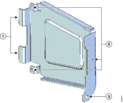
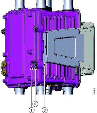
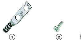
Figure 40 Security Panel Details
|
|
|
|---|---|
|
|
Insert the security panel tabs into the corresponding notches on the mounting bracket. |
|
|
Secure the security panel to the bracket at these locations, using the screws included in the Mounting Bracket Kit. |
|
|
Insert the captive screw located in the router door lock block through this hole when closing the router door. |
To install and secure the security panel to the bracket and router:
1.![]() Loosen the captive bolt that is located inside router door lock post. For lock post location, see Figure 59.
Loosen the captive bolt that is located inside router door lock post. For lock post location, see Figure 59.
2.![]() Install the security panel on the bracket by inserting the security panel tabs into the corresponding slots on the bracket as shown in Figure 41.
Install the security panel on the bracket by inserting the security panel tabs into the corresponding slots on the bracket as shown in Figure 41.
Note: For clarity, the router is not shown here. During this procedure, the router is mounted in the bracket.
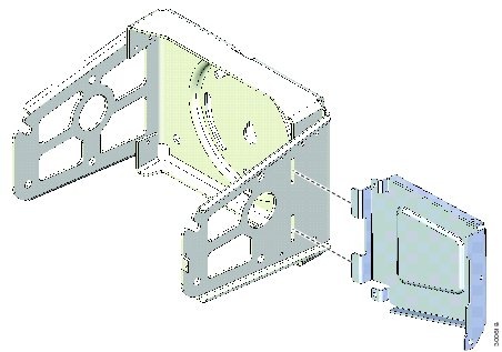
Figure 41 Assemble Bracket and Security Panel
3.![]() Swing the panel shut over the bracket, aligning the three screw holes on the panel with the corresponding holes on the bracket.
Swing the panel shut over the bracket, aligning the three screw holes on the panel with the corresponding holes on the bracket.
4.![]() Insert the three security panel screws (included in the mounting bracket kit) and tighten using the Phillips screw driver (see Figure 42).
Insert the three security panel screws (included in the mounting bracket kit) and tighten using the Phillips screw driver (see Figure 42).
The router door captive bolt inside the door lock post is aligned over the bracket hole as shown in Figure 43.
Note: For clarity, the router is not shown here. During this procedure, the router is mounted in the bracket.
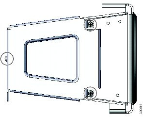
Figure 42 Security Panel Attached to Bracket with Included Screws
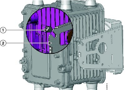
5.![]() Tighten the captive bolt (using 6-7 ft-lbs of torque) located inside the router door lock post ( 2 in Figure 43), ensuring the bolt extends into the security bracket ( 3 in Figure 43).
Tighten the captive bolt (using 6-7 ft-lbs of torque) located inside the router door lock post ( 2 in Figure 43), ensuring the bolt extends into the security bracket ( 3 in Figure 43).
Figure 43 Router Door Closed with Security Panel Installed
6.![]() Insert a lock that you provide through the router door lock post (Item 1 in Figure 43).
Insert a lock that you provide through the router door lock post (Item 1 in Figure 43).
The SD card can be accessed only by users who have access to the router door lock. The router can be removed from the mounting bracket only by users who have access to the router door lock.
Mounting the Router onto a Wall
The mounting bracket has wall-mount holes that you can use to mount the router directly onto a wall.
To mount the router on a wall, you must provide the hardware and anchors that can be used with the wall material in the installation environment.
Caution: The wall material and hardware that you use to mount the router must be able to support the weight of the router with two modules installed: approximately 23.0 pounds (10.4 Kg). The bolts must support a minimum of 150 in-lbs of pull out moment (FoS not included).
Router Orientation When Mounting
When mounting the router onto a wall, ensure that the router is oriented with the chassis cabling openings pointing downward so the router cable hangs down.
Caution: Never mount the router with the bottom (facing up) or to the side.
Identify an area on a wall that meets the safety, space, and environmental requirements described in Site Requirements.
Mount the router at a height where you can view the top of the module-side panel, and at which the cables can be managed without adding stress to the router ports.
Mount any reinforcement hardware that you provide to the wall the correct distance apart so that when the bolts are installed through the mounting bracket wall mount holes (Item 1, Figure 44), they align with the holes in the wall.
Figure 44 Distance for Wall-Mounting Hardware
■![]() Mounting bracket. For bracket dimensions, see Figure 44 and Figure 45.
Mounting bracket. For bracket dimensions, see Figure 44 and Figure 45.
■![]() Socket wrench that you supply
Socket wrench that you supply
■![]() 5/16th-in. or M8 bolts or equivalent (5) (customer supplied)
5/16th-in. or M8 bolts or equivalent (5) (customer supplied)
■![]() Bolt reinforcement hardware (for example, wall shoe anchor bolts) (5) (customer supplied)
Bolt reinforcement hardware (for example, wall shoe anchor bolts) (5) (customer supplied)
1.![]() Place the mounting bracket onto the location on the wall. Mark the locations of the four mounting holes and the one center hole.
Place the mounting bracket onto the location on the wall. Mark the locations of the four mounting holes and the one center hole.
2.![]() (If Required) Install the bolt reinforcement hardware onto the wall at the five hole locations.
(If Required) Install the bolt reinforcement hardware onto the wall at the five hole locations.
3.![]() Install the bolt into the center hole location. Do not fully thread in; leave bolt extended about 1/4”.
Install the bolt into the center hole location. Do not fully thread in; leave bolt extended about 1/4”.
4.![]() Align the center hole of the mounting bracket over the previously installed bolt so that the bracket rests on the bolt.
Align the center hole of the mounting bracket over the previously installed bolt so that the bracket rests on the bolt.
Figure 45 Securing the Wall-mount Bracket to the Wall
|
|
|
|---|---|
|
|
|
|
|
Customer-supplied hardware: 5/16th-in. or M8 bolts or equivalent (1) |
|
|
|
|
|
|
|
|
Customer-supplied hardware: 5/16th-in. or M8 bolds or equivalent (4) (same as #2 above) |
5.![]() Install the four mounting bolts through the bracket and into the wall.
Install the four mounting bolts through the bracket and into the wall.
Secure properly by hand-tightening in a star pattern order, beginning with the first bolt, tighten using the wrench. Torque based on hardware and wall material. Torque center bolt last.
6.![]() Install the router onto the mounting bracket. See Install the Router onto the Mounting Bracket.
Install the router onto the mounting bracket. See Install the Router onto the Mounting Bracket.
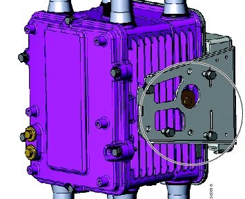
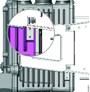
SD Card Slot Access for Bracket-Mounted Routers
When the Cisco mounting bracket is attached the router according to the instructions in this section, the bracket blocks access to the SD card port slot the router exterior.
Note: You must open or remove the mounting bracket security panel to see or access the SD card port.
To access the SD card slot ( 1) without removing the router from the bracket or any mounting installation that uses the bracket (refer to Figure 46):
1.![]() One one side of the router, remove the three bolts shown in Figure 37.
One one side of the router, remove the three bolts shown in Figure 37.
2.![]() Loosen but do not remove the fourth bolt that is inserted in the quick hang slot.
Loosen but do not remove the fourth bolt that is inserted in the quick hang slot.
3.![]() Repeat Step 1 through Step 2 on the other side of the router.
Repeat Step 1 through Step 2 on the other side of the router.
4.![]() Tilt the bracket on the quick mount slot, as shown in Figure 46.
Tilt the bracket on the quick mount slot, as shown in Figure 46.
Caution: When you finish using the SD card slot, reinstall and tighten all eight bolts with 6-7 foot-pounds of torque. The router must be securely attached to the mounting bracket with four bolts on each side.
Figure 46 Tilt Mounting Bracket for SD Card Slot Access
Grounding Instructions
In all installations, after the router is mounted, you must properly ground the unit according to the instructions in this section before connecting network and power cables as described in the Installing the Router.
Warning: This equipment must be externally grounded using a customer-supplied ground wire before power is applied. Contact the appropriate electrical inspection authority or an electrician if you are uncertain that suitable grounding is available. Statement 366
Warning: Installation of the equipment must comply with local and national electrical codes. Statement 1074
Grounding Hardware
The router is shipped with a grounding kit, shown in Figure 47.
Figure 47 Router Grounding Kit Contents
|
|
|
|
|---|---|---|
Materials You Supply
You must provide the tools listed in Materials and Tools You Supply.
Ground the Router
Note: You can perform these steps when the mounting bracket security panel is installed.
1.![]() Use the appropriate crimping tool or pliers to crimp the 6-gauge ground wire (included in the grounding kit) to the grounding lug.
Use the appropriate crimping tool or pliers to crimp the 6-gauge ground wire (included in the grounding kit) to the grounding lug.
2.![]() Connect the grounding lug to the router chassis ground connection point shown in Figure 48 using the supplied grounding screws.
Connect the grounding lug to the router chassis ground connection point shown in Figure 48 using the supplied grounding screws.
Note: Tighten the grounding screws to 20-24 in-lbs of torque. Do not overtighten!
3.![]() If necessary, strip the other end of the ground wire and connect it to a reliable earth ground, such as a grounding rod or an appropriate grounding point on a pole that is grounded.
If necessary, strip the other end of the ground wire and connect it to a reliable earth ground, such as a grounding rod or an appropriate grounding point on a pole that is grounded.
Figure 48 Grounding Lug Connectors (Chassis Ground Connection Point)
Bracket Dimensions
This section contains specifications for the Cisco mounting brackets used with the router, and includes:
■![]() Mounting Bracket Dimensions, Figure 49
Mounting Bracket Dimensions, Figure 49
■![]() Mounting Bracket Security Panel Dimensions, Figure 50
Mounting Bracket Security Panel Dimensions, Figure 50
■![]() Pole Plate Dimensions, Figure 51
Pole Plate Dimensions, Figure 51
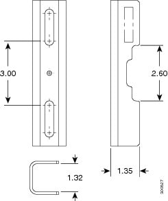
■![]() Pole Mount Plate Clamp Dimensions, Figure 52
Pole Mount Plate Clamp Dimensions, Figure 52
Figure 49 Mounting Bracket Dimensions
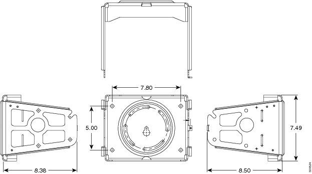
Figure 50 Mounting Bracket Security Panel Dimensions
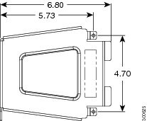
Figure 51 Pole Mount Plate Dimensions
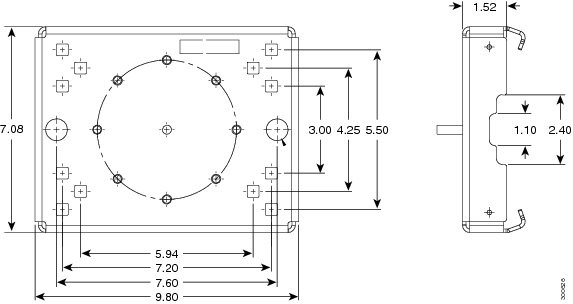
Figure 52 Pole Mount Plate Clamp Dimensions
 Feedback