- Information About OSPFv3
Configuring OSPFv3
This chapter describes how to configure Open Shortest Path First version 3 (OSPFv3) for IPv6 networks on the Cisco 1000 Series Connected Grid Routers (hereafter referred to as the Cisco CG-OS router).
The system software for the router is identified as the Cisco CG-OS software.
This chapter includes the following sections:
•![]() Guidelines and Limitations for OSPFv3
Guidelines and Limitations for OSPFv3
•![]() Verifying the OSPFv3 Configuration
Verifying the OSPFv3 Configuration
•![]() Configuration Examples for OSPFv3
Configuration Examples for OSPFv3
Information About OSPFv3
OSPFv3 is an IETF link-state protocol. An OSPFv3 router sends a special message, called a hello packet, out each OSPF-enabled interface to discover other OSPFv3 neighbor routers. Once a neighbor is discovered, the two routers compare information in the Hello packet to determine if the routers have compatible configurations. The neighbor routers attempt to establish adjacency, which means that the routers synchronize their link-state databases to ensure that they have identical OSPFv3 routing information. Adjacent routers share link-state advertisements (LSAs) that include information about the operational state of each link, the cost of the link, and any other neighbor information. The routers then flood these received LSAs out every OSPF-enabled interface so that all OSPFv3 routers eventually have identical link-state databases. When all OSPFv3 routers have identical link-state databases, the network is converged (see Convergence). Each router then uses Dijkstra's Shortest Path First (SPF) algorithm to build its route table.
You can divide OSPFv3 networks into areas. Routers send most LSAs only within one area, which reduces the CPU and memory requirements for an OSPF-enabled router.

Note ![]() OSPFv3 only supports IPv6 on the router. IPv4 is not supported.
OSPFv3 only supports IPv6 on the router. IPv4 is not supported.
For information about OSPFv2 for IPv4, see Configuring OSPFv2.
This section includes the following topics:
•![]() Comparison of OSPFv3 and OSPFv2
Comparison of OSPFv3 and OSPFv2
•![]() OSPFv3 and the IPv6 Unicast RIB
OSPFv3 and the IPv6 Unicast RIB
Comparison of OSPFv3 and OSPFv2
Much of the OSPFv3 protocol is the same as in OSPFv2. OSPFv3 is described in RFC 5340.
The key differences between the OSPFv3 and OSPFv2 protocols are as follows:
•![]() OSPFv3 expands on OSPFv2 to provide support for IPv6 routing prefixes and the larger size of IPv6 addresses.
OSPFv3 expands on OSPFv2 to provide support for IPv6 routing prefixes and the larger size of IPv6 addresses.
•![]() LSAs in OSPFv3 are expressed as prefix and prefix length instead of address and mask.
LSAs in OSPFv3 are expressed as prefix and prefix length instead of address and mask.
•![]() The router ID and area ID are 32-bit numbers with no relationship to IPv6 addresses.
The router ID and area ID are 32-bit numbers with no relationship to IPv6 addresses.
•![]() OSPFv3 uses link-local IPv6 addresses for neighbor discovery and other features.
OSPFv3 uses link-local IPv6 addresses for neighbor discovery and other features.
•![]() OSPFv3 uses IPv6 IPSec for authentication.
OSPFv3 uses IPv6 IPSec for authentication.
•![]() OSPFv3 redefines LSA types.
OSPFv3 redefines LSA types.
Hello Packet
OSPFv3 routers periodically send Hello packets on every OSPF-enabled interface. The hello interval determines how frequently the router sends these Hello packets and is configured per interface. OSPFv3 uses Hello packets for the following tasks:
•![]() Neighbor discovery
Neighbor discovery
•![]() Keepalives
Keepalives
•![]() Bidirectional communications
Bidirectional communications
•![]() Designated router election (see Designated Routers)
Designated router election (see Designated Routers)
The Hello packet contains information about the originating OSPFv3 interface and router, including the assigned OSPFv3 cost of the link, the hello interval, and optional capabilities of the originating router. An OSPFv3 interface that receives these Hello packets determines if the settings are compatible with the receiving interface settings. Compatible interfaces are considered neighbors and are added to the neighbor table (see Neighbors).
Hello packets also include a list of router IDs for the routers that communicate with the originating interface. When the receiving interface sees its own router ID in this list, that state confirms that bidirectional communication between the two interfaces exists.
OSPFv3 uses Hello packets as a keepalive message to determine if a neighbor is still communicating. If a router does not receive a Hello packet by the configured dead interval (usually a multiple of the hello interval), then the neighbor is removed from the local neighbor table.
Neighbors
An OSPFv3 interface must have a compatible configuration with a remote interface before the two are considered neighbors. The two OSPFv3 interfaces must match the following criteria:
•![]() Hello interval
Hello interval
•![]() Dead interval
Dead interval
•![]() Area ID (see Areas)
Area ID (see Areas)
•![]() Authentication
Authentication
•![]() Optional capabilities
Optional capabilities
When there is a match, the router enters the following information into the neighbor table:
•![]() Neighbor ID—The router ID of the neighbor router.
Neighbor ID—The router ID of the neighbor router.
•![]() Priority—Priority of the neighbor router. The priority is used for designated router election (see Designated Routers).
Priority—Priority of the neighbor router. The priority is used for designated router election (see Designated Routers).
•![]() State—Indication of whether the neighbor has just been heard from, is in the process of setting up bidirectional communications, is sharing the link-state information, or has achieved full adjacency.
State—Indication of whether the neighbor has just been heard from, is in the process of setting up bidirectional communications, is sharing the link-state information, or has achieved full adjacency.
•![]() Dead time—Indication of how long since the last Hello packet was received from this neighbor.
Dead time—Indication of how long since the last Hello packet was received from this neighbor.
•![]() Link-local IPv6 Address—The link-local IPv6 address of the neighbor.
Link-local IPv6 Address—The link-local IPv6 address of the neighbor.
•![]() Designated Router—Indication of whether the neighbor has been declared the designated router or backup designated router (see Designated Routers).
Designated Router—Indication of whether the neighbor has been declared the designated router or backup designated router (see Designated Routers).
•![]() Local interface—The local interface that received the Hello packet for this neighbor.
Local interface—The local interface that received the Hello packet for this neighbor.
When the first Hello packet is received from a new neighbor, the neighbor is entered into the neighbor table in the initialization state. Once bidirectional communication is established, the neighbor state becomes two-way. Start and exchange states come next, as the two interfaces exchange their link-state database. Once this is all complete, the neighbor moves into the full state, which signifies full adjacency. If the neighbor fails to send any Hello packets in the dead interval, then the neighbor is moved to the down state and it is no longer considered adjacent.
Adjacency
Adjacency is the path from each router to its local designated router (DR). Not all neighbors establish adjacency. Depending on the network type and designated router establishment, some neighbors become fully adjacent and share LSAs with all their neighbors, while other neighbors do not. For more information, see Designated Routers.
Adjacency is established using Database Description packets, Link State Request packets, and Link State Update packets in OSPFv3. The Database Description packet includes the LSA headers from the link-state database of the neighbor (see Link-State Database). The local router compares these headers with its own link-state database and determines which LSAs are new or updated. The local router sends a Link State Request packet for each LSA for which it needs new or updated information. The neighbor responds with a Link State Update packet. This exchange continues until both routers have the same link-state information.
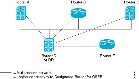
Designated Routers
Networks with multiple routers present a unique situation for OSPFv3. When every router floods the network with LSAs, multiple sources send the same link-state information. Depending on the type of network, OSPFv3 might use a single router, the designated router (DR), to control the LSA floods and represent the network to the rest of the OSPFv3 area (see Areas). When the DR fails, OSPFv3 selects a backup designated router (BDR).
Network types are as follows:
•![]() Point-to-point—A network that exists only between two routers. All neighbors on a point-to-point network establish adjacency and there is no DR.
Point-to-point—A network that exists only between two routers. All neighbors on a point-to-point network establish adjacency and there is no DR.
•![]() Broadcast—A network with multiple routers that can communicate over a shared medium that allows broadcast traffic, such as Ethernet. OSPFv3 routers establish a DR and BDR that controls LSA flooding on the network. OSPFv3 uses the well-known IPv6 multicast addresses, FF02::5, and a MAC address of 0100.5300.0005 to communicate with neighbors.
Broadcast—A network with multiple routers that can communicate over a shared medium that allows broadcast traffic, such as Ethernet. OSPFv3 routers establish a DR and BDR that controls LSA flooding on the network. OSPFv3 uses the well-known IPv6 multicast addresses, FF02::5, and a MAC address of 0100.5300.0005 to communicate with neighbors.
OSPFv3 selects the DR and BDR based on the information in the Hello packet. When an interface sends a Hello packet, it sets the priority field and the DR and BDR field when known. The routers follow an election procedure based on which routers declare themselves in the DR and BDR fields and the priority field in the Hello packet. As a final determinant, OSPFv3 chooses the highest router IDs as the DR and BDR.
All other routers establish adjacency with the DR and the BDR and use the IPv6 multicast address FF02::6 to send LSA updates to the DR and BDR. Figure 6-1 shows this adjacency relationship between all routers and the DR.
DRs are based on a router interface. A router might be the DR for one network and not for another network on a different interface.
Figure 6-1 Designated Router in Multi-Access Network
Areas
Figure 6-2 OSPFv3 Areas
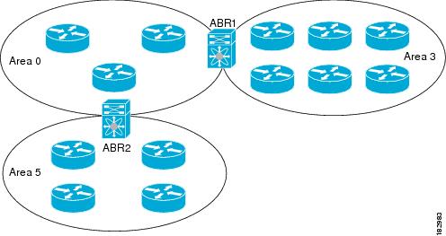
The ABR has a separate link-state database for each area to which it connects. The ABR sends Inter-Area Prefix (type 3) LSAs (see Route Summarization) from one connected area to the backbone area. The backbone area sends summarized information about one area to another area. In Figure 6-2, Area 0 sends summarized information about Area 5 to Area 3.
OSPFv3 defines an additional router type: the autonomous system boundary router (ASBR). This router connects an OSPFv3 area to another autonomous system.
Link-State Advertisement
OSPFv3 uses link-state advertisements (LSAs) to build its routing table.
This section includes the following topics:
•![]() Flooding and LSA Group Pacing
Flooding and LSA Group Pacing
LSA Types
Table 6-1 shows the LSA types supported by the Cisco CG-OS software.
|
|
|
|
|---|---|---|
1 |
Router LSA |
LSA sent by every router. This LSA includes the state and cost of all links but does not include prefix information. Router LSAs trigger an SPF recalculation. Router LSAs are flooded to the local OSPFv3 area. |
2 |
Network LSA |
LSA sent by the DR. This LSA lists all routers in the multi-access network but does not include prefix information. Network LSAs trigger an SPF recalculation. See Designated Routers. |
3 |
Inter-Area Prefix LSA |
LSA sent by the area border router to an external area for each destination in local area. This LSA includes the link cost from the border router to the local destination. See Areas. |
4 |
Inter-Area Router LSA |
LSA sent by the area border router to an external area. This LSA advertises the link cost to the ASBR only. See Areas. |
5 |
AS External LSA |
LSA generated by the ASBR. This LSA includes the link cost to an external autonomous system destination. AS External LSAs are flooded throughout the autonomous system. See Areas. |
7 |
Type-7 LSA |
LSA generated by the ASBR within an NSSA. This LSA includes the link cost to an external autonomous system destination. Type-7 LSAs are flooded only within the local NSSA. See Areas. |
8 |
Link LSA |
LSA sent by every router, using a link-local flooding scope (see Flooding and LSA Group Pacing. This LSA includes the link-local address and IPv6 prefixes for this link. |
9 |
Intra-Area Prefix LSA |
LSA sent by every router. This LSA includes any prefix or link state changes. Intra-Area Prefix LSAs are flooded to the local OSPFv3 area. This LSA does not trigger an SPF recalculation. |
11 |
Grace LSAs |
LSA sent by a restarting router, using a link-local flooding scope. This LSA is used for a graceful restart of OSPFv3. See Graceful Restart. |
Link Cost
Each OSPFv3 interface has a link cost. The cost is an arbitrary number. By default, the Cisco CG-OS software assigns a cost that is the configured reference bandwidth divided by the interface bandwidth. By default, the reference bandwidth is 40 Gb/s. The link cost is carried in the LSA updates for each link.
Flooding and LSA Group Pacing
OSPFv3 floods LSA updates to different sections of the network, depending on the LSA type. OSPFv3 uses the following flooding scopes:
•![]() Link-local—LSA is flooded only on the local link. Used for Link LSAs and Grace LSAs.
Link-local—LSA is flooded only on the local link. Used for Link LSAs and Grace LSAs.
•![]() Area-local—LSA is flooded throughout a single OSPFv3 area only. Used for Router LSAs, Network LSAs, Inter-Area-Prefix LSAs, Inter-Area-Router LSAs, and Intra-Area-Prefix LSAs.
Area-local—LSA is flooded throughout a single OSPFv3 area only. Used for Router LSAs, Network LSAs, Inter-Area-Prefix LSAs, Inter-Area-Router LSAs, and Intra-Area-Prefix LSAs.
•![]() AS scope—LSA is flooded throughout the routing domain. An AS scope is used for AS External LSAs.
AS scope—LSA is flooded throughout the routing domain. An AS scope is used for AS External LSAs.
LSA flooding guarantees that all routers in the network have identical routing information. LSA flooding depends on the OSPFv3 area configuration (see Areas). The LSAs are flooded based on the link-state refresh time (every 30 minutes by default). Each LSA has its own link-state refresh time.
You can control the flooding rate of LSA updates in your network by using the LSA group pacing feature. LSA group pacing can reduce high CPU or buffer utilization. This feature groups LSAs with similar link-state refresh times to allow OSPFv3 to pack multiple LSAs into an OSPFv3 Update message.
By default, LSAs with link-state refresh times within four minutes of each other are grouped together. You should lower this value for large link-state databases or raise it for smaller databases to optimize the OSPFv3 load on your network.
Link-State Database
Each router maintains a link-state database for the OSPFv3 network. This database contains all the collected LSAs and includes information on all the routes through the network. OSPFv3 uses this information to calculate the best path to each destination and populates the routing table with these best paths.
The router removes LSAs from the link-state database when it does not receive an LSA update within a set interval (MaxAge). Routers flood a repeat of the LSA every 30 minutes to prevent aging out of accurate link-state information. The Cisco CG-OS software supports the LSA grouping feature to prevent all LSAs from refreshing at the same time. For more information, see Flooding and LSA Group Pacing.
Multi-Area Adjacency
OSPFv3 multi-area adjacency allows you to configure a link on the primary interface that is in more than one area. This link becomes the preferred intra-area link in those areas. Multi-area adjacency establishes a point-to-point unnumbered link in an OSPFv3 area that provides a topological path for that area. The primary adjacency uses the link to advertise an unnumbered point-to-point link in the Router LSA for the corresponding area when the neighbor state is full.
The multi-area interface exists as a logical construct over an existing primary interface for OSPFv3; however, the neighbor state on the primary interface is independent of the multi-area interface. The multi-area interface establishes a neighbor relationship with the corresponding multi-area interface on the neighboring router. See Configuring Multi-Area Adjacency for more information.
OSPFv3 and the IPv6 Unicast RIB
OSPFv3 runs the Dijkstra shortest path first algorithm on the link-state database. This algorithm selects the best path to each destination based on the sum of all the link costs for each link in the path. The shortest path for each destination is then put in the OSPFv3 route table. When the OSPFv3 network is converged, this route table feeds into the IPv6 unicast RIB. OSPFv3 communicates with the IPv6 unicast RIB to do the following:
•![]() Add or remove routes
Add or remove routes
•![]() Provide convergence updates to remove stale OSPFv3 routes and for stub router advertisements (see Multiple OSPFv3 Instances)
Provide convergence updates to remove stale OSPFv3 routes and for stub router advertisements (see Multiple OSPFv3 Instances)
OSPFv3 also runs a modified Dijkstra algorithm for fast recalculation for Inter-Area Prefix, Inter-Area Router, AS-External, type-7, and Intra-Area Prefix (type 3, 4, 5, 7, 8) LSA changes.
Address Family Support
The Cisco CG-OS software supports multiple address families, such as unicast IPv6 and multicast IPv6. OSPFv3 features that are specific to an address family are as follows:
•![]() Default routes
Default routes
•![]() Route summarization
Route summarization
•![]() Filter lists for border routers
Filter lists for border routers
•![]() SPF optimization
SPF optimization
Use the address-family ipv6 unicast command to enter the IPv6 unicast address family configuration mode when configuring these features.
Advanced Features
The Cisco CG-OS software supports advanced OSPFv3 features that enhance the usability and scalability of OSPFv3 in the network.
This section includes the following topics:
Stub Area
You can limit the amount of external routing information that floods an area by making it a stub area. A stub area is an area that does not allow AS External (type 5) LSAs (see Link-State Advertisement). These LSAs usually flood the local autonomous system to propagate external route information. Stub areas have the following requirements:
•![]() All routers in the stub area must be stub routers. See Stub Routing.
All routers in the stub area must be stub routers. See Stub Routing.
•![]() No ASBR routers exist in the stub area.
No ASBR routers exist in the stub area.
•![]() You cannot configure virtual links in the stub area.
You cannot configure virtual links in the stub area.
Figure 6-3 shows an example of an OSPFv3 autonomous system where all routers in area 0.0.0.10 have to go through the ABR to reach external autonomous systems. Area 0.0.0.10 can be configured as a stub area.
Figure 6-3 Stub Area
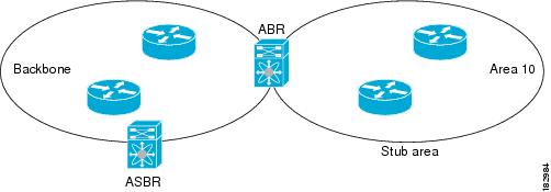
Stub areas use a default route for all traffic that needs to go through the backbone area to the external autonomous system. The default route is an Inter-Area-Prefix LSA with the prefix length set to 0 for IPv6.
Not-So-Stubby Area
A Not-So-Stubby Area (NSSA) is similar to the stub area, except that an NSSA allows you to import autonomous system external routes within an NSSA using redistribution. The NSSA ASBR redistributes these routes and generates type-7 LSAs that it floods throughout the NSSA. You can optionally configure the ABR that connects the NSSA to other areas to translate this type-7 LSA to AS External (type 5) LSAs. The ABR then floods these AS External LSAs throughout the OSPFv3 autonomous system.
The router supports summarization and filtering during the translation. See Link-State Advertisement for details on type-7 LSAs.
You can, for example, use NSSA to simplify administration when you are connecting a central site using OSPFv3 to a remote site that is using a different routing protocol. Before NSSA, the connection between the corporate site border router and a remote router could not be run as an OSPFv3 stub area because routes for the remote site could not be redistributed into a stub area. With NSSA, you can extend OSPFv3 to cover the remote connection by defining the area between the corporate site router and remote router as an NSSA (see Configuring NSSA).
The backbone area 0 cannot be an NSSA.
Virtual Links
Virtual links allow you to connect an OSPFv3 area ABR to a backbone area ABR when a direct physical connection is not available. Figure 6-4 shows a virtual link that connects Area 3 to the backbone area through Area 5.
Figure 6-4 Virtual Links
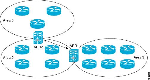
You can also use virtual links to temporarily recover from a partitioned area, which occurs when a link within the area fails, isolating part of the area from reaching the designated ABR to the backbone area.
Route Summarization
Because OSPFv3 shares all learned routes with every OSPF-enabled router, you might want to use route summarization to reduce the number of unique routes that are flooded to every OSPF-enabled router. Route summarization simplifies route tables by replacing more-specific addresses with an address that represents all the specific addresses. For example, you can replace 2010:11:22:0:1000::1 and 2010:11:22:0:2000:679:1 with one summary address, 2010:11:22::/48.
Typically, you would summarize at the boundaries of area border routers (ABRs). Although you could configure summarization between any two areas, it is better to summarize in the direction of the backbone so that the backbone receives all the aggregate addresses and injects them, already summarized, into other areas.
Inter-area route summarization
You configure inter-area route summarization on ABRs, summarizing routes between areas in the autonomous system. To take advantage of summarization, assign network numbers in areas in a contiguous way to be able to lump these addresses into one range.
Graceful Restart
OSPFv3 automatically restarts if the process experiences problems. After the restart, OSPFv3 initiates a graceful restart so that the platform is not taken out of the network topology. When you manually restart OSPFv3, it performs a graceful restart, which is similar to a stateful switchover. The
Cisco CG-OS software applies the running configuration in both cases.
A graceful restart, also known as nonstop forwarding (NSF), allows OSPFv3 to remain in the data forwarding path through a process restart. When OSPFv3 needs to restart, it first sends a link-local Grace (type 11) LSA.
The Grace LSA includes a grace period, which is a specified time that the neighbor OSPFv3 interfaces hold onto the LSAs from the restarting OSPFv3 interface. (Typically, OSPFv3 tears down the adjacency and discards all LSAs from a down or restarting OSPFv3 interface.) The participating neighbors, which are called NSF helpers, keep all LSAs that originate from the restarting OSPFv3 interface as if the interface were still adjacent.
When the restarting OSPFv3 interface is operational again, it rediscovers its neighbors, establishes adjacency, and starts sending its LSA updates again. At this point, the NSF helpers recognize that graceful restart has finished.
Note ![]() When the restarting OSPFv3 interface does not come back up before the end of the grace period, or if the network experiences a topology change, then the OSPFv3 neighbors tear down adjacency with the restarting OSPFv3 and treat it as a normal OSPFv3 restart.
When the restarting OSPFv3 interface does not come back up before the end of the grace period, or if the network experiences a topology change, then the OSPFv3 neighbors tear down adjacency with the restarting OSPFv3 and treat it as a normal OSPFv3 restart.
Multiple OSPFv3 Instances
The Cisco CG-OS software supports multiple instances of the OSPFv3 protocol. By default, every instance uses the same system router ID. You must manually configure the router ID for each instance if the instances are in the same OSPFv3 autonomous system.
The OSPFv3 header includes an instance ID field to identify that OSPFv3 packet for a particular OSPFv3 instance. You can assign the OSPFv3 instance. The interface drops all OSPFv3 packets that do not have a matching OSPFv3 instance ID in the packet header.
The Cisco CG-OS software allows only one OSPFv3 instance on an interface.
SPF Optimization
The Cisco CG-OS software optimizes the SPF algorithm in the following ways:
•![]() Partial SPF for Network (type 2) LSAs, Inter-Area Prefix (type 3) LSAs, and AS External (type 5) LSAs—When there is a change on any of these LSAs, the Cisco CG-OS software performs a faster partial calculation rather than running the whole SPF calculation.
Partial SPF for Network (type 2) LSAs, Inter-Area Prefix (type 3) LSAs, and AS External (type 5) LSAs—When there is a change on any of these LSAs, the Cisco CG-OS software performs a faster partial calculation rather than running the whole SPF calculation.
•![]() SPF timers—You can configure different timers for controlling SPF calculations. These timers include exponential backoff for subsequent SPF calculations. The exponential backoff limits the CPU load of multiple SPF calculations.
SPF timers—You can configure different timers for controlling SPF calculations. These timers include exponential backoff for subsequent SPF calculations. The exponential backoff limits the CPU load of multiple SPF calculations.
Prerequisites for OSPFv3
You must be familiar with routing fundamentals to configure OSPFv3.
You have completed the OSPFv3 network strategy and planning for your network. For example, you must decide whether to implement multiple areas.
You are familiar with IPv6 addressing and basic configuration. See Chapter 3 "Configuring IPv6" for information on IPv6 routing and addressing.
You must be logged on to the router.
You have enabled OSPFv3 (see Enabling OSPFv3).
You have configured at least one interface for IPv6 that is capable of communicating with a remote OSPFv3 neighbor.
Guidelines and Limitations for OSPFv3
The Cisco CG-OS software displays areas in dotted decimal notation regardless of whether you enter the area in decimal or dotted decimal notation.
Default Settings
Table 6-2 lists the default settings for OSPFv3 parameters.
Configuring Basic OSPFv3
Be sure to review the Prerequisites for OSPFv3 and Guidelines and Limitations for OSPFv3 sections before configuring OSPFv3.
This section includes the following topics:
•![]() Configuring Networks in OSPFv3
Configuring Networks in OSPFv3
Enabling OSPFv3
You must enable OSPFv3 before you can configure OSPFv3.
BEFORE YOU BEGIN
No prerequisites.
DETAILED STEPS
EXAMPLE
This example shows how to enable OSPFv3 on the router.
router# configure terminal
router(config)#feature ospfv3
router(config)# copy running-config startup-config
To disable the OSPFv3 feature and remove all associated configurations, use the no feature ospfv3 command in configuration mode.
Creating an OSPFv3 Instance
The first step in configuring OSPFv3 is to create an instance or OSPFv3 instance. You assign a unique instance tag for this OSPFv3 instance. The instance tag can be any string. For each OSPFv3 instance, you can also configure the following optional parameters:
•![]() Router ID—Configures the router ID for this OSPFv3 instance. If you do not use this parameter, the router ID selection algorithm is used. For more information, see the Router IDs.
Router ID—Configures the router ID for this OSPFv3 instance. If you do not use this parameter, the router ID selection algorithm is used. For more information, see the Router IDs.
•![]() Administrative distance—Rates the trustworthiness of a routing information source. For more information, see the Administrative Distance.
Administrative distance—Rates the trustworthiness of a routing information source. For more information, see the Administrative Distance.
•![]() Log adjacency changes—Creates a system message whenever an OSPFv3 neighbor changes its state.
Log adjacency changes—Creates a system message whenever an OSPFv3 neighbor changes its state.
•![]() Maximum paths—Sets the maximum number of equal paths that OSPFv3 installs in the route table for a particular destination. Use this parameter for load balancing between multiple paths.
Maximum paths—Sets the maximum number of equal paths that OSPFv3 installs in the route table for a particular destination. Use this parameter for load balancing between multiple paths.
•![]() Reference bandwidth—Controls the calculated OSPFv3 cost metric for a network. The calculated cost is the reference bandwidth divided by the interface bandwidth. You can override the calculated cost by assigning a link cost when a network is added to the OSPFv3 instance. For more information, see Configuring Networks in OSPFv3.
Reference bandwidth—Controls the calculated OSPFv3 cost metric for a network. The calculated cost is the reference bandwidth divided by the interface bandwidth. You can override the calculated cost by assigning a link cost when a network is added to the OSPFv3 instance. For more information, see Configuring Networks in OSPFv3.
For more information about OSPFv3 instance parameters, see Configuring Advanced OSPFv3.
BEFORE YOU BEGIN
You must enable OSPFv3 (see Enabling OSPFv3).
Enter the show ospfv3 instance-tag command to verify that the instance tag is not in use on this router.
OSPFv3 must be able to obtain a router identifier (for example, a configured loopback address) or you must configure the router ID option (see Step 3 below).
DETAILED STEPS
EXAMPLE
This example shows how to create an OSPFv3 instance on the router.
router# configure terminal
router(config)# router ospfv3 201
router(config-router)# log-adjacency-changes
router(config-router)# address-family
router(config-router-af)# distance 200
router(config-router-af)# exit
router(config-router)# copy running-config startup-config
To remove the OSPFv3 instance and all associated configuration, use the no router ospfv3 instance-tag command in configuration mode.
Note ![]() When operating in the interface mode, the no router ospfv3 instance-tag command does not remove all associated OSPFv3 configurations. You must manually remove any associated OSPFv3 commands for the interface.
When operating in the interface mode, the no router ospfv3 instance-tag command does not remove all associated OSPFv3 configurations. You must manually remove any associated OSPFv3 commands for the interface.
Configuring Networks in OSPFv3
You can configure a network to OSPFv3 by associating it through the interface that the router uses to connect to that network (see Neighbors). You can add all networks to the default backbone area (Area 0), or you can create new areas using any decimal number or an IP address.
Note ![]() All areas must connect to the backbone area either directly or through a virtual link.
All areas must connect to the backbone area either directly or through a virtual link.
Note ![]() When configuring OSPFv3 on an interface, you must assign a valid IPv6 address to that interface before you can enable OSPFv3 on the interface.
When configuring OSPFv3 on an interface, you must assign a valid IPv6 address to that interface before you can enable OSPFv3 on the interface.
BEFORE YOU BEGIN
You must enable OSPFv3 on the router (see Enabling OSPFv3).
DETAILED STEPS
EXAMPLE
This example shows how to add an interface to a OSPFv3 instance 201 and area a network area 0.0.0.10.
router# configure terminal
router(config)# interface ethernet 2/1
router(config-if)# ipv6 address 2001:0DB8::1/48
router(config-if)# ipv6 ospfv3 201 area 0.0.0.10
router(config-if)# copy running-config startup-config
OPTIONAL PARAMETERS
You can configure the following optional parameters for OSPFv3 in interface configuration mode.
|
|
|
|---|---|
ospfv3 cost number |
Configures the OSPFv3 cost metric for this interface. The default is to calculate a cost metric, based on the reference bandwidth and interface bandwidth. The range is from 1 to 65535. |
ospfv3 dead-interval seconds |
Configures the OSPFv3 dead interval, in seconds. The range is from 1 to 65535. The default is four times the hello interval, in seconds. |
ospfv3 hello-interval seconds |
Configures the OSPFv3 hello interval, in seconds. The range is from 1 to 65535. The default is 10 seconds. |
ospfv3 mtu-ignore |
Configures OSPFv3 to ignore any IP maximum transmission unit (MTU) mismatch with a neighbor. The default is to not establish adjacency if the neighbor MTU does not match the local interface MTU. |
ospfv3 network {broadcast | point-point} |
Sets the OSPFv3 network type. |
ospfv3 passive-interface |
Suppresses routing updates on the interface. |
ospfv3 priority number |
Configures the OSPFv3 priority, used to determine the DR for an area. The range is from 0 to 255. The default is 1. See Designated Routers. |
ospfv3 shutdown |
Shuts down the OSPFv3 instance on the interface. |
Configuring Advanced OSPFv3
Configure OSPFv3 after you have designed your OSPFv3 network.
This section includes the following topics:
•![]() Configuring Filter Lists for Border Routers
Configuring Filter Lists for Border Routers
•![]() Configuring a Totally Stubby Area
Configuring a Totally Stubby Area
•![]() Configuring Multi-Area Adjacency
Configuring Multi-Area Adjacency
•![]() Configuring Route Summarization
Configuring Route Summarization
•![]() Restarting an OSPFv3 Instance
Restarting an OSPFv3 Instance
Configuring Filter Lists for Border Routers
You can separate your OSPFv3 domain into a series of areas that contain related networks. All areas must connect to the backbone area through an area border router (ABR). OSPFv3 domains can connect to external domains as well through an autonomous system border router (ASBR). See Areas.
ABRs have the following optional configuration parameters:
•![]() Area range—Configures route summarization between areas. For more information, see Configuring Route Summarization.
Area range—Configures route summarization between areas. For more information, see Configuring Route Summarization.
•![]() Filter list—Filters the Inter-Area Prefix (type 3) LSAs on an ABR that are allowed in from an external area.
Filter list—Filters the Inter-Area Prefix (type 3) LSAs on an ABR that are allowed in from an external area.
ASBRs also support filter lists.
BEFORE YOU BEGIN
You must enable OSPFv3 (see Enabling OSPFv3).
DETAILED STEPS
EXAMPLE
This example shows how to define a filter-list for OSPFv3 area 0.0.0.10:
router# configure terminal
router(config)# router ospfv3 201
router(config-router)# address-family ipv6 unicast
router(config-router-af)# area 0.0.0.10 filter-list route-map FilterLSAs in
router(config-router-af)# show ipv6 ospfv3 policy statistics area 0.0.0.10 filter-list in
router(config-router-af)# copy running-config startup-config
To terminate an OSPFv3 routing process, use the no router ospfv3 instance-tag command in configuration mode.
Configuring Stub Areas
You can configure a stub area for part of an OSPFv3 domain where external traffic is not necessary. Stub areas block AS External (type 5) LSAs, limiting unnecessary routing to and from selected networks. See Stub Area. You can optionally block all summary routes from going into the stub area.
BEFORE YOU BEGIN
You must enable OSPFv3 (see Enabling OSPFv3).
Ensure that there are no virtual links or ASBRs in the proposed stub area.
DETAILED STEPS
EXAMPLE
This example shows how to create a stub area that blocks all summary route updates:
router# configure terminal
router(config)# router ospfv3 201
router(config-router)# area 0.0.0.10 stub no-summary
router(config-router)# copy running-config startup-config
To terminate an OSPFv3 routing process, use the no router ospfv3 instance-tag command in the configuration mode.
Configuring a Totally Stubby Area
You can create a totally stubby area and prevent all summary route updates from going into the stub area.
To create a totally stubby area, use the following command in router configuration mode.
|
|
|
|---|---|
area area-id stub no-summary |
Creates an area as a totally stubby area. |
EXAMPLE
This example shows how to create a totally stub area that blocks all summary route updates from entering the stub area.
router(config-router)# area 20 stub no-summary
To remove an OSPFv3 stub area, use the no area area-id stub [no-summary] command in router mode.
Configuring NSSA
You can configure an NSSA for part of an OSPFv3 domain where limited external traffic is required. See Not-So-Stubby Area. You can optionally translate this external traffic to an AS External (type 5) LSA and flood the OSPFv3 domain with this routing information.
An NSSA can be configured with the following optional parameters:
•![]() Default information originate—Generates a Type-7 LSA for a default route to the external autonomous system. Use this option on an NSSA ASBR if the ASBR contains the default route in the routing table. This option can be used on an NSSA ABR whether or not the ABR contains the default route in the routing table.
Default information originate—Generates a Type-7 LSA for a default route to the external autonomous system. Use this option on an NSSA ASBR if the ASBR contains the default route in the routing table. This option can be used on an NSSA ABR whether or not the ABR contains the default route in the routing table.
•![]() No redistribution—Redistributes routes that bypass the NSSA to other areas in the OSPFv3 autonomous system. Use this option when the NSSA ASBR is also an ABR.
No redistribution—Redistributes routes that bypass the NSSA to other areas in the OSPFv3 autonomous system. Use this option when the NSSA ASBR is also an ABR.
•![]() No summary—Blocks all summary routes from flooding the NSSA. Use this option on the NSSA ABR.
No summary—Blocks all summary routes from flooding the NSSA. Use this option on the NSSA ABR.
•![]() Route map—Filters the external routes to limit those routes that the router floods throughout the NSSA and other areas.
Route map—Filters the external routes to limit those routes that the router floods throughout the NSSA and other areas.
•![]() Suppress—Suppresses the forwarding address in translated LSAs. The ABR uses 0.0.0.0 as the forwarding IPV4 address.
Suppress—Suppresses the forwarding address in translated LSAs. The ABR uses 0.0.0.0 as the forwarding IPV4 address.
•![]() Translate—Translates Type-7 LSAs to AS External (type 5) LSAs for areas outside the NSSA. Use this command on an NSSA ABR to flood the redistributed routes throughout the OSPFv3 autonomous system. You can optionally suppress the forwarding address in these AS External LSAs.
Translate—Translates Type-7 LSAs to AS External (type 5) LSAs for areas outside the NSSA. Use this command on an NSSA ABR to flood the redistributed routes throughout the OSPFv3 autonomous system. You can optionally suppress the forwarding address in these AS External LSAs.
BEFORE YOU BEGIN
You must enable OSPF (see Enabling OSPFv3).
Ensure that there are no virtual links in the proposed NSSA and that it is not the backbone area.
DETAILED STEPS
EXAMPLE
This example shows how to create an NSSA that blocks all summary route updates.
router# configure terminal
router(config)# router ospfv3 201
router(config-router)# area 0.0.0.10 nssa no-summary
router(config-router)# copy running-config startup-config
This example shows how to create an NSSA that generates a default route.
router# configure terminal
router(config)# router ospfv3 201
router(config-router)# area 0.0.0.10 nssa default-info-originate
router(config-router)# copy running-config startup-config
This example shows how to create an NSSA that filters external routes and blocks all summary route updates.
router# configure terminal
router(config)# router ospfv3 201
router(config-router)# area 0.0.0.10 nssa route-map ExternalFilter no-summary
router(config-router)# copy running-config startup-config
This example shows how to create an NSSA that always translates Type-7 LSAs to AS External (type 5) LSAs.
router# configure terminal
router(config)# router ospfv3 201
router(config-router)# area 0.0.0.10 nssa translate type 7 always
router(config-router)# copy running-config startup-config
This example shows how to create an NSSA that always translates Type-7 LSAs to AS External (type 5) LSAs but does not place the Type-7 forwarding addresses into the AS External (type 5) LSAs.
router# configure terminal
router(config)# router ospfv3 201
router(config-router)# area 0.0.0.10 nssa translate type 7 suppress-fa
router(config-router)# copy running-config startup-config
To remove the NSSA, use the no area command in the router mode.
Configuring Multi-Area Adjacency
You can add more than one area to an existing OSPFv3 interface. The additional logical interfaces support multi-area adjacency.
BEFORE YOU BEGIN
You must enable OSPFv3 on the router (see Enabling OSPFv3).
Ensure that you have configured a primary area for the interface (see Configuring Networks in OSPFv3.)
DETAILED STEPS
EXAMPLE
This example shows how to add a second area to an OSPFv3 interface.
router# configure terminal
router(config)# interface ethernet 2/1
router(config-if)# ipv6 router ospfv3 multi-area 20
router(config-if)# copy running-config startup-config
To remove the multi-area adjacency on the OSPFv3 interface, use the no ipv6 router ospfv3 multi-area area-id command.
Configuring Virtual Links
A virtual link connects an isolated area to the backbone area through an intermediate area. See Virtual Links. You can configure the following optional parameters for a virtual link:
•![]() Authentication—Sets simple password or MD5 message digest authentication and associated keys.
Authentication—Sets simple password or MD5 message digest authentication and associated keys.
•![]() Dead interval—Sets the time that a neighbor waits for a Hello packet before declaring the local router as dead and tearing down adjacencies.
Dead interval—Sets the time that a neighbor waits for a Hello packet before declaring the local router as dead and tearing down adjacencies.
•![]() Hello interval—Sets the time between successive Hello packets.
Hello interval—Sets the time between successive Hello packets.
•![]() Retransmit interval—Sets the estimated time between successive LSAs.
Retransmit interval—Sets the estimated time between successive LSAs.
•![]() Transmit delay—Sets the estimated time to transmit an LSA to a neighbor.
Transmit delay—Sets the estimated time to transmit an LSA to a neighbor.
Note ![]() You must configure the virtual link on both routers involved before the link becomes active.
You must configure the virtual link on both routers involved before the link becomes active.
BEFORE YOU BEGIN
You must enable OSPFv3 (see Enabling OSPFv3).
DETAILED STEPS
EXAMPLE
These examples show how to create a simple virtual link between two ABRs.
Configuration for ABR 1 (router ID 2001:0DB8::1) is as follows.
router# configure terminal
router(config)# router ospfv3 201
router(config-router)# area 0.0.0.10 virtual-link 2001:0DB8::10
router(config-router-vlink)# copy running-config startup-config
Configuration for ABR 2 (router ID 2001:0DB8::10) is as follows.
router# configure terminal
router(config)# router ospfv3 101
router(config-router)# area 0.0.0.10 virtual-link 2001:0DB8::1
router(config-router-vlink)# copy running-config startup-config
To remove a virtual link on the OSPFv3 interface, use the no area area-id virtual link router router-id command.
OPTIONAL COMMANDS
You can configure the following optional commands in virtual link configuration mode.
Configuring Route Summarization
You can configure route summarization for inter-area routes by configuring an address range that is summarized. For more information, see Route Summarization.
BEFORE YOU BEGIN
You must enable OSPF (see Enabling OSPFv3).
DETAILED STEPS
EXAMPLE
This example shows how to create summary addresses between areas on an ABR.
router# configure terminal
router(config)# router ospfv3 201
router(config-router)# address-family ipv6 unicast
router(config-router-af)# area 0.0.0.10 range 2001:0DB8::/48
router(config-router)# copy running-config startup-config
This example shows how to create summary addresses on an ASBR.
router# configure terminal
router(config)# router ospfv3 201
router(config-router)# address-family ipv6 unicast
router(config-router-af)# summary-address 2001:0DB8::/48
router(config-router)# copy running-config startup-config
To terminate an OSPFv3 routing process, use the no router ospfv3 instance-tag command in the configuration mode.
Modifying the Default Timers
OSPFv3 includes a number of timers that control the behavior of protocol messages and shortest path first (SPF) calculations.
Each of the following parameters comes with a default setting which you can modify.
•![]() OSPFv3 includes the following timer parameters at the router configuration mode:
OSPFv3 includes the following timer parameters at the router configuration mode:
–![]() Group pacing LSAs—Sets the interval at which LSAs are collected into a group and refreshed, checksummed, or aged. This timer controls how frequently LSA updates occur and optimizes how many are sent in an LSA update message (see Flooding and LSA Group Pacing).
Group pacing LSAs—Sets the interval at which LSAs are collected into a group and refreshed, checksummed, or aged. This timer controls how frequently LSA updates occur and optimizes how many are sent in an LSA update message (see Flooding and LSA Group Pacing).
–![]() LSA arrival time—Sets the minimum interval allowed between the same LSA arriving from an OSPFv3 neighbor. The Cisco CG-OS software drops all LSAs that arrive faster than the set minimal interval time.
LSA arrival time—Sets the minimum interval allowed between the same LSA arriving from an OSPFv3 neighbor. The Cisco CG-OS software drops all LSAs that arrive faster than the set minimal interval time.
–![]() Throttle LSAs—Sets rate limits for generating LSAs. This timer controls how frequently LSAs are generated after a topology change occurs.
Throttle LSAs—Sets rate limits for generating LSAs. This timer controls how frequently LSAs are generated after a topology change occurs.
–![]() Throttle SPF calculation—Controls how frequently the SPF calculation is run.
Throttle SPF calculation—Controls how frequently the SPF calculation is run.
•![]() OSPFv3 includes the following timer parameters at the interface configuration mode:
OSPFv3 includes the following timer parameters at the interface configuration mode:
–![]() Retransmit interval—Sets the estimated time between successive LSAs.
Retransmit interval—Sets the estimated time between successive LSAs.
–![]() Transmit delay—Sets the estimated time to transmit an LSA to a neighbor.
Transmit delay—Sets the estimated time to transmit an LSA to a neighbor.
For information on the hello interval and dead timer, refer to Configuring Networks in OSPFv3
BEFORE YOU BEGIN
You must enable OSPFv3 (see Enabling OSPFv3).
DETAILED STEPS
EXAMPLE
This example shows how to control LSA flooding with the lsa-group-pacing option.
router# configure terminal
router(config)# router ospfv3 201
router(config-router)# timers lsa-group-pacing 300
router(config-router)# copy running-config startup-config
To return to the default settings for a timer, use the no option for each command as shown in the example below.
router(config-router)# no timers throttle lsa
Configuring Graceful Restart
Graceful restart is enabled by default. You can configure the following optional parameters for graceful restart in an OSPFv3 instance:
•![]() Grace period—Configures how long neighbors must wait after a graceful restart has started before tearing down adjacencies.
Grace period—Configures how long neighbors must wait after a graceful restart has started before tearing down adjacencies.
•![]() Helper mode disabled—Disables helper mode on the local OSPFv3 instance. OSPFv3 does not participate in the graceful restart of a neighbor.
Helper mode disabled—Disables helper mode on the local OSPFv3 instance. OSPFv3 does not participate in the graceful restart of a neighbor.
•![]() Planned graceful restart only—Configures OSPFv3 to support graceful restart only in the event of a planned restart.
Planned graceful restart only—Configures OSPFv3 to support graceful restart only in the event of a planned restart.
BEFORE YOU BEGIN
You must enable OSPFv3 (See Enabling OSPFv3).
Ensure that all neighbors are configured for graceful restart with matching optional parameters set.
DETAILED STEPS
EXAMPLE
This example shows how to enable graceful restart on the router after it was disabled and then set the grace period to 120 seconds.
router# configure terminal
router(config)# router ospfv3 201
router(config-router)# graceful-restart
router(config-router)# graceful-restart grace-period 120
router(config-router)# copy running-config startup-config
Restarting an OSPFv3 Instance
You can restart an OSPv3 instance. This action clears all neighbors for the instance.
To restart an OSPFv3 instance and remove all associated neighbors, use the following command.
|
|
|
|---|---|
restart ospfv3 instance-tag |
Restarts the OSPFv3 instance and removes all neighbors. |
Verifying the OSPFv3 Configuration
To display the OSPFv3 configuration, enter any or all of the following commands.
Monitoring OSPFv3
To display OSPFv3 statistics, use the following commands.
Configuration Examples for OSPFv3
This example shows how to configure OSPFv3.
feature ospfv3
router ospfv3 201
router-id 290.0.2.1
interface ethernet 2/1
ipv6 address 2001:0DB8::1/48
ipv6 ospfv3 201 area 0.0.0.10
 Feedback