IP Address Management

Feature Summary and Revision History

Summary Data

Table 1. Summary Data

Applicable Product(s) or Functional Area

cnBNG

Applicable Platform(s)

SMI

Feature Default Setting

Disabled - Configuration Required

Related Changes in this Release

Not Applicable

Related Documentation

Not Applicable

Revision History

Table 2. Revision History
Revision Details Release

Introduced periodic reconciliation support for IPAM.

2025.03.0

Introduced offline address range support to the IANA and IAPD Allocation from Same IP Range feature.

2025.03.0

Introduced support for allocating IANA and IAPD from same IP pool.

2025.01.0

Introduced support for IPAM Asynchronous route programming.

2024.04.0

Introduced support for pre-allocation of Gateway IP and address chunks.

2024.04.0

Introduced support for Variable Chunk Size for an IPAM Data Plane.

2024.01.0

First introduced.

2021.01.0

Feature Description

IP Address Management (IPAM) is a method of tracking and managing IP addresses of a network. IPAM is one of the core components of the subscriber management system. Traditional IPAM functionalities are insufficient in Cloud-Native network deployments. Hence, IPAM requires additional functionalities to work with the Cloud-Native subscriber management system. The Cloud-Native IPAM system is used in various network functions, such as Session Management function (SMF), Policy Charging function (PCF), and Broadband Network Gateway (BNG).

The IPAM system includes the following functionalities to serve the Cloud Native and Control and User Plane Separation (CUPS) architecture:

  • Centralized IP Resource Management—Based on the needs of the Internet Service Provider (ISP), the Control Plane (CP) is deployed either on a single (centralized) cluster or multiple (distributed) clusters. For multiple cluster deployments, the IPAM automatically manages the single IP address space across the multiple CPs that are deployed in the distributed environment.

  • IP Address-Range Reservation per User Plane—For subscribers connecting to the Internet core, the User Plane (UP) provides the physical connectivity. The UP uses the summary-routes to advertise subscriber routes to the Internet core. For CPs that are managing multiple UPs, the CP reserves a converged IP subnet to the UPs. In such a scenario, the IPAM splits the available address space into smaller address-ranges and assigns it to different UPs.

  • IP Address Assignment from Pre-Reserved Address-Ranges—When subscribers request for an IP address, the IPAM assigns addresses from the pre-reserved address range of their respective UP.

IPAM Components

This section describes the different components of the IPAM system.

IPAM Sub-Modules

The IPAM functionalities are categorized in the following sub-modules:

IPAM Server

This module manages the complete list of pools and address-space configurations. It splits the configured address-ranges into smaller address-ranges (statically or dynamically) to distribute it to the IPAM Cache modules. The IPAM server can be deployed as a centralized entity to serve a group of CN clusters or as an integrated entity within a single cluster.

IPAM Cache

This module acquires the free address-ranges from the IPAM server and allocates individual IP addresses to the IPAM clients. The IPAM cache is generally deployed in the Distributed mode running within each cluster, to communicate with the co-located or remotely located IPAM server. It is also responsible for address-range reservation per UP and pool threshold monitoring. The IPAM server and cache modules can also run in an integrated mode.

IPAM Client

This module is tightly coupled with its respective network-function, responsible for handling request and release of individual IP address from the IPAM cache for each IP managed end-device.

Unlike the IPAM server and cache module, the IPAM client caters to use-cases specific to network-functions such as BNG, SMF, PCF, and so on.

IPAM Integration in cnBNG

The Cloud-Native Broadband Network Gateway (cnBNG) function comprises of loosely coupled microservices that provide the functionality of the BNG. The decomposition of these microservices is based on the following three-layered architecture:

  1. Layer 1: Protocol and Load Balancer Services (Stateless)

  2. Layer 2: Application services (Stateless)

  3. Layer 3: Database Services (Stateful)

The IPAM and cnBNG integration occurs in the Application Services layer.

BNG Node Manager Application—The BNG Node Manager application is responsible for the User Plane function (UPF) management, ID and resource management, and IP address management. Therefore, the IPAM Cache is integrated as part of this microservice.

Also, the UPF uses the IPAM Client module for address-range-reservation per UPF.

BNG DHCP and PPPOE Application—The BNG-DHCP and BNG-PPOE pods are responsible for providing IP addresses to the BNG subscriber session. During session bring-up, the IP address is requested and during session bring-down, the IP address is released back. These First Sign of Life (FSOL) applications send the inter-process communications (IPC) to the Resource Manager (RMGR) component in the NodeMgr. The NodeMgr receives the IPC and invokes the IPAM component.

IPAM Server Application—Based on the deployment model, the IPAM Server runs as an independent microservice as part of the same cluster or in a remote cluster.

In standalone deployments, the IPAM Server functionality is an integral part of the IPAM Cache, that is, it runs as part of the Node Manager microservice itself.

How it Works

This section describes the call flow pertaining to the integration of the IPAM in the cnBNG.

Call Flows

This section describes the following IPAM call flows in cnBNG:

  • IPAM initial sequence call flow

  • IPAM call flow

  • IPAM static-pool call flow

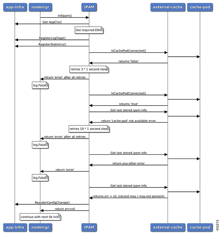
IPAM Initial Sequence Call Flow

This section describes the cnBNG initial sequence call-flow.

Figure 1. IPAM Initial Sequence Call Flow


Table 3. IPAM Initial Sequence Call Flow Description

Step

Description

1

IPAM reads the required environments, registers with the application infrastructure for log-tags, metrics, and database connection.

2

IPAM restores the previous state from the cache-pod, if present.

3

IPAM registers for configuration change and applies the new configuration change, if any. -change, apply new config-changes if any

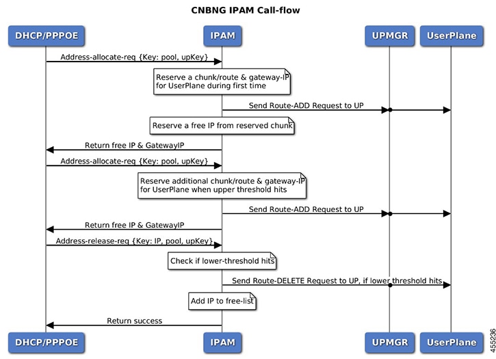
IPAM Call Flow

This section describes the cnBNG IPAM call-flow.

Figure 2. IPAM Call Flow


Table 4. IPAM Call Flow Description

Step

Description

1

IPAM receives the ‘addr-alloc’ request from the DHCP or PPPoE pod with pool-name, addr-type and user plane function (UPF) as input.

2

IPAM reserves a new address-range (if not already present for UPF) and sends a ROUTE-ADD message to the UPF. It waits for a success or failure response. If the receives a failure response, it removes the chunk and repeats this step.

3

IPAM reserves a free-IP from the assigned address-range and returns to the DHCP or PPPoE.

4

IPAM monitors the ‘upper-threshold’ for each UPF during each IP address-allocation and also has a background thread that monitors. It then assigns new address-ranges to the UPF and repeats the ROUTE-ADD flow.

5

IPAM receives the ‘addr-free’ request from the DHCP or PPPoE pod with pool-name, addr-type, addr or pfx, and UPF as input.

6

IPAM moves the addr or pfx first to the quarantine-list until the quarantine timer and later moves it to the free-list.

7

IPAM monitors the ‘lower-threshold’ (currently 0%) of the address-range of each UPF, removes the address-range from the UPF, and sends the ROUTE-DELETE message.

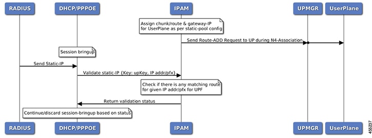
IPAM Static-Pool Call Flow

This section describes the IPAM static-pool call flow.

Figure 3. IPAM Static Pool Call Flow


Table 5. IPAM Call Flow Description

Step

Description

1

IPAM receives the ‘addr-alloc’ request from the DHCP or PPPoE pod with pool-name, addr-type and user plane function (UPF) as input.

2

IPAM reserves a new address-range (if not already present for UPF) and sends a ROUTE-ADD message to the UPF. It waits for a success or failure response. If the receives a failure response, it removes the chunk and repeats this step.

3

IPAM reserves a free-IP from the assigned address-range and returns to the DHCP or PPPoE.

4

IPAM monitors the ‘upper-threshold’ for each UPF during each IP address-allocation and also has a background thread that monitors. It then assigns new address-ranges to the UPF and repeats the ROUTE-ADD flow.

5

IPAM receives the ‘addr-free’ request from the DHCP or PPPoE pod with pool-name, addr-type, addr or pfx, and UPF as input.

6

IPAM moves the addr or pfx first to the quarantine-list until the quarantine timer and later moves it to the free-list.

7

IPAM monitors the ‘lower-threshold’ (currently 0%) of the address-range of each UPF, removes the address-range from the UPF, and sends the ROUTE-DELETE message.

Limitations

The IPAM feature has the following limitations:

  • Duplicate IP address is not supported within a pool.

  • Duplicate IP address is not supported across pools, that belong to same VRF.

  • Removal of ‘pool’ is not supported while addresses are already assigned.

  • Removal or modification of IP-address-ranges is not supported while addresses are already assigned.

  • Change of ‘source’ field is not supported while address or prefixes are already assigned.

  • Change of ‘vrf-name’ of pool is not supported while address or prefixes are already assigned.

  • Start-address should be less than the End-address.

  • Configuring addr-range split-size in wrong manner, that is, size of address-range < size-of-per-cache < size-of-dp, is not supported.

  • Configuring IPv6 Address (IANA) and Prefix (IAPD) values interchangeably is not supported.

  • Configuring invalid ‘prefix-length’ for Prefix (IAPD) range is not supported.

Configuring IPAM Feature

This section describes how to configure the IPAM feature.

Configuring the IPAM feature involves the following steps:

  1. Configuring IPAM source

  2. Configuring the global threshold

  3. Configure IPAM address pool

  4. Configuring IPv4 address ranges

  5. Configuring IPv6 address ranges

  6. Configuring IPv6 prefix ranges

  7. Configuring the IPv4 threshold

  8. Configuring the IPv6 threshold

  9. Configuring IPv4 address range split

  10. Configuring IPv6 address and prefix address-range split

Configuring IPAM Source

Use the following configuration to configure the IPAM source.

config 
   ipam 
      source local 
         threshold { ipv4-add percentage | ipv6-address percentage | ipv6-prefix percentage } 
         commit 

NOTES:

  • ipam : Enters the IPAM Configuration mode.

  • source local : Enters the local datastore as the pool source.

  • threshold { ipv4-add percentage | ipv4-address percentage | ipv6-prefix percentage } : Specifies the threshold in percentage for the following:

    • ipv4-add percentage : Specifies the IPv4 threshold. The valid values range from 1 to 100. The default value is 80.

    • ipv6-add percentage : Specifies the IPv4 threshold. The valid values range from 1 to 100. The default value is 80.

    • ipv6-prefix percentage : Specifies the IPv6 threshold prefix. The valid values range from 1 to 100. The default value is 80.

Configuring Global Threshold

Use the following configuration to configure the global threshold.

config 
   ipam 
      threshold 
         ipv4-addr percentage 
         ipv6-addr percentage 
         ipv6-prefix percentage 
         commit 

NOTES:

  • ipam : Enters the IPAM Configuration mode.

  • threshold : Enters the threshold sub-mode.

  • ipv4-add percentage : Specifies the IPv4 threshold. The valid values range from 1 to 100. The default value is 80.

  • ipv6-add percentage : Specifies the IPv4 threshold. The valid values range from 1 to 100. The default value is 80.

  • ipv6-prefix percentage : Specifies the IPv6 threshold prefix. The valid values range from 1 to 100. The default value is 80.

Configuring IPAM Address Pool

Use the following configuration to configure the IPAM address pool.

config 
   ipam 
      address-pool pool_name [ address-quarantine-timer ] [offline ] [ static user_plane_name ] [ vrf-name string ] 
      commit 

NOTES:

  • ipam : Enters the IPAM configuration mode.

  • address-pool pool_name [ address-quarantine-timer ] [offline ] [ static user_plane_name ] [ vrf-name string ] : Configures the address pool configuration. pool_name must be the name of the address pool.

    This command configures the following parameters:

    • offline : Sets the address pool to offline mode.

    • static user_plane_name : Specifies the 'user-plane' name associated to this static-pool.

    • vrf-name string : Configures the Virtual routing and forwarding (VRF) name of the pool.

Configuring IPv4 Address Ranges

Use the following configuration to configure the IPv4 address ranges.

config 
   ipam 
      address-pool pool_name 
         ipv4 
            address-range start_ipv4_address end_ipv4_address [ default-gateway ipv4_address ] [ offline ] 
            commit 

NOTES:

  • ipam : Enters the IPAM configuration mode.

  • address-pool pool_name : Configures the address pool configuration. pool_name must be the name of the address pool.

  • ipv4 : Enters the IPv4 mode of the pool.

  • address-range start_ipv4_address end_ipv4_address [ default-gateway ipv4_address ] [ offline ] : Configures the IPv4 address range with the starting and ending IPv4 address.

    • default-gateway ipv4_address : Specifies the IPv4 address of the default gateway.

    • offline : Sets the address pool to offline mode.

Configuring IPv6 Address Ranges

Use the following configuration to configure the IPv6 address ranges:

config 
   ipam 
      address-pool pool_name 
         ipv6 
            address-range start_ipv6_address end_ipv6_address [ offline ] 
            commit 

NOTES:

  • ipam : Enters the IPAM configuration mode.

  • address-pool pool_name : Configures the address pool configuration. pool_name must be the name of the address pool.

  • ipv6 : Enters the IPv6 mode of the pool.

  • address-range start_ipv6_address end_ipv6_address [ offline ] : Configures the IPv6 address range with the starting and ending IPv6 address.

    [ offline ] : Sets the address pool to offline mode.

Configuring IPv6 Prefix Ranges

Use the following configuration to configure the IPv6 prefix ranges:

config 
   ipam 
      address-pool pool_name 
         ipv6  
            prefix-ranges 
               prefix-range prefix_value prefix-length prefix_length 
               commit 

NOTES:

  • ipam : Enters the IPAM configuration mode.

  • address-poolpool_name : Configures the address pool configuration. pool_name must be the name of the address pool.

  • ipv6 : Enters the IPv6 mode of the pool.

  • prefix-ranges : Enters the prefix ranges mode.

  • prefix-range prefix_value prefix-length length : Configures the IPv6 prefix range. prefix_value specifies the IPv6 prefix range.

    prefix-length length specifies the IPv6 prefix length.

Configuring IPv4 Threshold

Use the following configuration to configure the IPv4 threshold:

config 
   ipam 
      address-pool  pool_name 
         ipv4 
            threshold 
               upper-threshold  percentage 
               commit 

NOTES:

  • ipam : Enters the IPAM Configuration mode.

  • address-pool pool_name : Configures the address pool configuration. pool_name must be the name of the address pool.

  • ipv4 : Enters the IPv4 mode of the pool.

  • threshold : Enters the threshold sub-mode.

  • upper-threshold percentage : Specifies the IPv4 upper threshold value in percentage. The valid values range from 1 to 100. The default value is 80.

The following is a sample configuration:

config
   ipam
      address-pool p1
         ipv4
            threshold
               upper-threshold 80

Configuring IPv6 Prefix-Range Threshold

Use the following configuration to configure the IPv6 prefix-range threshold.

config 
   ipam 
      address-pool pool_name 
         ipv6 
            prefix-ranges 
               threshold 
                  upper-threshold percentage 
                  commit 

NOTES:

  • ipam : Enters the IPAM configuration mode.

  • address-pool pool_name : Configures the address pool configuration. pool_name must be the name of the address pool.

  • ipv6 : Enters the IPv6 mode of the pool.

  • prefix-ranges : Enters the IPv6 prefix ranges sub-mode.

  • threshold : Enters the threshold sub-mode.

  • upper-threshold percentage : Specifies the IPv6 upper-threshold value in percentage.

The following is an example configuration:

config
   ipam
      address-pool p3
         ipv6
            prefix-ranges
               threshold
                  upper-threshold 78

Configuring IPv4 Address Range Split

Use the following configuration to configure the IPv4 address range split.

config 
   ipam 
      address-pool pool_name 
         ipv4 
            [ no ] split-size { per-cache value | per-dp value } 
            commit 

NOTES:

  • ipam : Enters the IPAM configuration mode.

  • -address-pool pool_name : Configures the address pool configuration. pool_name must be the name of the address pool.

  • ipv4 : Enters the IPv4 mode of the pool.

  • [ no ] split-size { per-cache value | per-dp value } : Specifies the size of the IPv4 range to be split for each IPAM cache allocation. The IPAM server consumes this configuration. The no form of this command disables the splitting of the address-ranges into smaller chunks.

    per-cache value : Specifies the size of the IPv4 range to be split for each Data-Plane (User-Plane) allocation. The valid values range from 2 to 262144. The default value is 1024.

    The IPAM cache consumes this configuration.

  • per-dp value : Specifies the size of the IPv4 range to be split for each Data-Plane (User-Plane) allocation. The valid values range from 2 to 262144 The default value is 256.

    The IPAM cache consumes this configuration.

Configuring IPv6 Address and Prefix Address-Range-Spilt

Use the following configuration to configure the IPv6 address and prefix address range spilt.

config 
   ipam 
      address-pool pool_name 
         ipv6 
            address-ranges 
               [ no ] spilt-size { per-cache value | per-dp value } 
               commit 
            prefix-ranges 
               [ no ] spilt-size { per-cache value | per-dp value } 
               commit 

NOTES:

  • ipam : Enters the IPAM configuration mode.

  • address-pool pool_name : Configures the address pool. pool_name must be the name of the address pool.

  • ipv6 : Enters the IPv6 mode of the pool.

  • [ no ] spilt-size { per-cache value | per-dp value } : Specifies the size of the IPv6 range to be split for each IPAM cache allocation. The IPAM server consumes this configuration. The no form of this command disables the splitting of the address-ranges into smaller chunks.

    per-cache value : Specifies the size of the IPv6 range to be spilt for each Data-Plane (User-Plane) allocation. The valid values range from 2 to 262144. The default value is 1024.

    The IPAM cache consumes this configuration.

  • per-dp value : Specifies the size of the IPv6 range to be spilt for each Data-Plane (User-Plane) allocation. The valid values range from 2 to 262144 The default value is 256.

    The IPAM cache consumes this configuration.

Configuring Variable Chunk Size Support for an IPAM Data Plane

Use the following commands to configure the IPAM tags:

ipam
 instance instance_id
  source local
  address-pool pool_name
   tags
    group tag_value
   exit
   pool-priority
    priority <0>
   exit 
   

NOTES:

  • ipam : Enters the IPAM configuration.

  • instance instance_id : Specifies the IPAM instance and enters the instance sub-mode. instance_id must be an integer. The valid value ranges from 1 to 8.

  • source local : Enters the local datastore as the pool source.

  • address-pool pool_name : Specifies the name of the pool to enter the pool configuration. pool_name must be the name of the address pool

  • tags group tag_value : Specifies the tag group value of the pool. All pools carrying the same tag group value can be associated to a DHCP profile using the keyword pool-group-tag and the corresponding tag group value. The value must be a string.

  • pool-priority priority value: Specifies the order of IP chunk and IP allocation among pools with the same tag value. value must be the integer 0 or 1. 0 is the default value, and has the highest priority. .

Use the following commands to configure DHCP for pool association:

profile dhcp dhcp_profile_name
 ipv4
  server
   pool-group-tag tag_value 
   lease hours hours_value
  exit
 exit
exit
 

NOTES:

  • profile dhcp dhcp_profile_name : Specifies the DHCP profile name.

  • ipv4 : Enters IPv4 configuration mode.

  • server : Enters server configuration mode.

  • pool-group-tag tag_value : Specifies the group tag value that is used to associate the profile with the group tag defined in the pool.

IPAM Enhancements

This section lists the following IPAM enhancements.

IPAM Quarantine Timer

The IP quarantine logic enhancements are as follows:

  • The maximum quarantine configuration is increased to 1 hour (Range: 4 to 3600 seconds).

  • If the configured quarantine time is <= 15min, additional buffer of 60 seconds is added to the configured quarantine time.

  • If the configured quarantine time is > 15min, additional buffer of 5 minutes is added to the configured quarantine time.

  • Default quarantine time processing thread interval is changed from 5 to 60 seconds.

  • The IP is moved to the free-list after ~(configured-qTime + buffer + delay-from-qt-thread-processing).

  • Upon Node Manager pod restart, quarantine time of all older IPs in the quarantine time-queue is reset and will restart from beginning.

  • After Node Manager pod restart, all IPs released as part of reconciliation are moved to the quarantine-queue before moving to the free-bitmap (this includes pre-reserved IPs).

Address-Range Level Quarantine

If an address-range is removed from the UPF after releasing all the IPs in a proper manner (that is, each released IP went through quarantine time) then the address-range is moved directly to free-list.

If an address-range is removed from the UPF due to the UPF-release with some of the addresses allocated, then the complete address-range is put under quarantine for the configured time and then moved to free-list.

The show ipam pool command displays quarantine-chunks with a special ‘alloc-context’.

Pool and UPF Threshold Monitoring

The UPF threshold monitoring enhancements are as follows:

  • Upper threshold: Default = 80%, configurable. This is used to add new chunks to the pool or UPF.

  • SafeCutOff: Default = (upper-threshold-5%), not-configurable. After hitting upper-threshold, new chunks are allocated to the pool or UPF to bring down the current-utilization to safecutoff level , that is, upper-threshold – 5%.

  • Lower threshold: Default = 90% of upper-threshold, not-configurable. This is used to remove a chunk from the pool or UPF.

Each Node Manager runs a pool level threshold monitoring. When a chunk is assigned to the UPF, the Node Manager checks the pool-threshold hit and reserves additional chunks from the cache-pod for future use.

For pool threshold calculation, the total number of IPs left in free-chunks are considered; not the actual number of allocated IPs on an assigned chunk. That is, after a chunk is assigned to the UPF, it is considered as fully used for pool-threshold monitoring purpose. A complete free address-range can be released back to the cache-pod based on lower-threshold calculation.

For UPF threshold monitoring, the actual number of total IPs and allocated IPs are considered; more chunks are reserved for the UPF when the upper-threshold hits. The Node Manager adds the route to the UPF whenever a new chunk is assigned to it due to the threshold hit. For performance reasons, the route is not deleted if it was added in at the last minute.

The upper threshold is configurable (default=80%), when this threshold hits, new chunks are added until the current-utilization falls back to the safe-cutoff level. That is, 75% is safe cutoff if the upper-threshold is 80%.

Lower threshold is 90% of the upper-threshold. Thati is, if the upper-threshold is 80%, then the lower-threshold is 72%, a chunk can be removed from the UPF only when the remaining threshold is below 72%. Otherwise, the chunk remains in the UPF assigned list. This logic is applied to avoid frequent route-add and route-delete operations around boundary condition. The UPF threshold monitoring is triggered during events such as address-allocate, address-release, and config-change. On idle-system, the behavior may differ, however, in a running system, the threshold calculation occurs regularly.

Marking a pool or address-range as offline overrides the lower-threshold logic. That is, if an offline chunk is completely free, it is removed from the UPF irrespective of the lower-threshold calculation.

Multiple Replica Handling

IPAM is part of the Node Manager (nodemgr) pod. A maximum of two nodemgr pods are supported per BNG cluster.

During UPF-registration, one of the nodemgr pod gets all the static-pool-routes for the UPF and all the dynamic-pool-routes from both the nodemgr pod if anything is allocated earlier and programs it.

During IP-allocation, the IPC request goes to one of the nodemgr pods. If no routes were assigned earlier, a new route is assigned and if successful, an IP is returned to FSOL. Even if one nodemgr pod goes down, the other nodemgr can handle IP-allocations, provided enough IPs are available. Chunks that are reserved by one nodemgr cannot be used by the other nodemgr for address-allocations.

During IP-release, the IPC request should go to the IP owner nodemgr as best-effort. If the IPC fails due, then the IP become stale on the IPAM. During nodemgr bring-up, the CDL reconciliation occcurs, which recovers the stale IPs. In addition, a new CLI is added reconcile-ipam to manually trigger IPAM-CDL reconciliation on a need basis. This command should be executed only during maintenance because it is a heavy operation.

During the UPF release, the N4 release comes to one of the nodemgrs. It sends an internal-IPC to the other nodemgr and both clean-up all the routes assigned to the respective UPF. If one of the nodemgr is down during that time, the other nodemgr takes over the content and releases the chunks on behalf of its peer.

Periodic reconciliation

Periodic reconciliation is a system process that

  • periodically and automatically reviews IP address records for inconsistencies

  • identifies and reclaims stale or unused IP addresses, and

  • increases system reliability by using robust bulk record retrieval methods.

This feature ensures that IPAM maintains accurate records of IP address usage and reduces the risk of address exhaustion caused by unreleased or orphaned IP allocations.

Table 6. Feature History

Feature Name

Release Information

Description

Periodic reconciliation

2025.03.0 You can now keep your IP address records accurate and avoid address exhaustion. This feature automatically identifies and reclaims stale IP addresses through a periodic, automated process, making management easier and more reliable.

Traditionally, IPAM systems might not have performed regular reconciliation to release stale IP addresses. With this feature, a new automated routine streamlines the cleanup of unused or stale IPs, improving overall IP utilization.

Key aspects:

  • Periodic routine: The process runs automatically based on a user-configurable frequency (defined in days).

  • Automatic cleanup: Stale IP addresses are identified and released with no manual intervention required, enhancing IP address utilization and operational efficiency.

  • Configuration: You can enable reconciliation flows and configure their frequency within the IPAM instance settings. By default, this process is disabled and requires explicit setup.

Reconciliation scenarios

There are three main scenarios for running reconciliation in the current system:

  1. Automatic reconciliation by Node Manager (NM)

    NM runs reconciliation automatically when a pod restarts or during a CP-GR role switchover.

  2. Manual trigger of reconciliation

    You can manually trigger reconciliation if you detect inconsistencies between IP allocation in IP address management (IPAM) and the CDL session count.

  3. Periodic reconciliation

    To avoid manual intervention, you can schedule periodic reconciliation. This feature automatically detects and fix discrepancies between IPAM and CDL session data.


Note


It is recommended to schedule periodic reconciliation during periods of low system activity (for example, at midnight) to reduce any potential performance impact.


Configure periodic reconciliation

Set up periodic reconciliation to automatically reclaim stale IP addresses and maintain accurate IPAM records.

Use this configuration when you want IPAM to automatically identify and clean up unused or stale IP allocations without requiring manual intervention.

Procedure


Enter IPAM instance configuration mode, and configure the reconciliation schedule as needed.

Example:

config 
 ipam 
  instance  gr_instance_id 
   reconcile-schedule
    time-of-day-hour hour_of_day
    time-of-day-minute mins
    frequency days
   end 

NOTES:

  • reconcile-schedule : Configures the reconciliation schedule.

  • time-of-day-hour hour : Specifies the hour of day when reconciliation should run. The time values are in the cluster time zone and use the 24-hour format (0–23).

  • time-of-day-minute mins : Specifies the minute of the hour when reconciliation should start. The value ranges from 0 to 59.

  • frequency days : Specifies how frequently (in days) reconciliation should run. The value ranges from 1 to 30.

Example:

This is a sample configuration to run reconciliation daily at 03:15 AM for IPAM instance 1:

config
 ipam
  instance 1
   reconcile-schedule
    time-of-day-hour 3
    time-of-day-minute 15
    frequency 1
   end
  exit
 exit

IPAM automatically performs reconciliation at the specified time and frequency to regularly clean up stale IP addresses.

IPAM Route Programming Enhancements

Table 7. Feature History

Feature Name

Release Information

Description

IPAM Route Programming Enhancements

2024.04.0

IPAM now programs routes asynchronously, improving system stability and performance.

IPAM sends route update requests and handles responses in separate routines, allowing continuous address allocation without delays.

Prior to Release 2024.04.0, IPAM programs routes toward UP in a synchronous manner. This means IPAM waits for a response from UP before processing any other requests for that AFI. If there is a delay in the route update response from UP, goroutines on the Node Manager (NM) start to pile up. Significant delays can cause the NM to crash. Also, new address allocations on IPAM remain blocked until the response is received.

Asynchronous Route Programming Implementation

Starting Release 2024.04.0, the IPAM is enhanced to program routes asynchronously. IPAM sends the route update request and waits for the response in a separate routine. Based on the response, IPAM moves the chunks to the proper state.

Scenarios for Route Programming

IPAM programs routes toward UP in two scenarios:

  • When the first subscriber comes to IPAM for a given AFI on an NM.

  • When there is a threshold hit for the UP or SRG-Group for that AFI on NM.

Scenario 1: First Subscriber

When the first subscriber comes to IPAM for a given AFI, the behavior remains unchanged. IPAM programs the route for that UP in a synchronous manner. This usually happens during the initial system setup, where delays are not expected. Since IPAM handles UP or SRG-Group registration during this flow, it remains synchronous for simplicity.

Scenario 2: Threshold Hit

When there is a threshold hit for a given UP or SRG-Group for an AFI, IPAM fetches new chunks from NM or Cachepod, and programs the route toward the UP or SRG-Group asynchronously. This ensures no impact on existing or new IP allocations.

No explicit configuration is required for this functionality. This feature becomes applicable as new routes are programmed for the UP. The system checks the PFCP retransmission timeout configuration, and if this configuration is set, the route retry is done based on the configured timeout. Otherwise, by default, the retry occurs after 15 seconds plus a 5-second buffer.

The following is a sample PFCP retransmission timeout configuration:

instance instance-id 1
 endpoint n4-protocol
  retransmission timeout 15 max-retry 1
 exit
exit

Pre-Allocation of Gateway IP and Address Chunks

Table 8. Feature History

Feature Name

Release Information

Description

Pre-Allocation of Gateway IP and Address Chunks

2024.04.0 This feature ensures a smoother and more efficient onboarding process for new subscribers by reserving the first IP address in the allocated chunk for gateway functionalities.

Gateway IP Allocation

In a routed network configuration, the subscriber's gateway IP resides at the first Layer 3 hop on the access side router. The gateway IP is the first IP address within the allocated chunk or address range for the access side router. This first IP address is reserved and will not be assigned to any subscribers. Reserving this IP ensures that it is consistently available for gateway functionalities.

Address Chunk Pre-Allocation

Before onboarding the first subscriber, it is necessary to pre-allocate the address chunk and the first IP address within this chunk. This pre-allocation allows the first IP to be programmed on the access side router in advance, ensuring that the network infrastructure is prepared before any subscribers connect. Pre-allocating the chunk is mandatory for session bring up on routed SRG groups.

Administrative Command for Pre-Allocation

To support this pre-allocation process, we have introduced a new administrator-triggered command, ipam-address-chunk allocate . This command enables the pre-allocation of the address chunk and the gateway IP. Administrators must use this command whenever a new access interface or port is onboarded. If there are multiple BNG access interfaces on the same access router, pre-allocation must be performed multiple times.

Address Chunk Release

You can also release an IP address chunk when the data plane (DP) is released, particularly after bringing down subscribers. During the removal of an SRG group, it is mandatory to follow the Method of Procedure (MOP), which includes bringing down all subscribers in the group and executing an action command (ipam-address-chunk release ) to release the DP and its associated chunks. If the action command is used to release an address-chunk without bringing down subscribers, the DP is unregistered, and the chunk is moved to quarantine. The ipam-address-chunk allocate command is intended for the initial IP reservation; subsequent chunk allocations for the DP occurs only when the IP usage threshold is reached. If you execute the action command a second time, the command execution will succeed, but no additional chunk will be allocated.

Configure Pre-Allocation of Gateway IP and Address Chunks

Procedure


Step 1

Use the ipam-address-chunk action command to configure pre-allocation of Gateway IP and address chunks.

Example:


ipam-address-chunk { allocate | release { [ pool-group-tag value | pool-name name ]} 
      { address-type [ ipv6-addr | ipv6-prefix | ipv4 | ipv6 ] }
      [ ipam-dp-key dp_key ] 
 	  [ gr-instance  gr_instance ]
      [ srg-peer-id  srg_peer_id ]
       

NOTES:

  • allocate : Enables pre-allocation of IP address chunk and the gateway IP.

  • release : Releases an IP address chunk.

  • pool-group-tag / pool-name : Provide either the pool-name or the pool-group-tag, and this should match the pool information configured in the DHCP profile.

  • address-type : Specify one of the four possible address types:

    • ipv6-addr

    • ipv6-prefix

    • ipv4

    • ipv6

      Note


      When the ipam-address-chunk action command is executed with the ipv6 address type, IPAM checks for a pool configured with split-prefix-iana-first enabled and allocates both IANA and IAPD from the same prefix. If no such pool is found, an error is returned.

    This is a mandatory parameter.

  • ipam-dp-key : Specifies the data plane key for IP management. This is a mandatory parameter.

    • Routed SRG case: Indicates the value of ipam-dp-key specified in the DHCP pool. Currently, circuit-id is supported. Essentially, use the value of circuit-id set on the access-side OLT.

    • Non-Routed SRG case: The ipam-dp-key can either be the same as the srg-peer-id or it can be different.

    • Non-Routed Non SRG case: This scenario is not supported currently.

    • Routed Non SRG case: This scenario is not supported currently.

  • gr-instance: Specifies the GR instance information. If not provided, the local gr-instance is used as the default value. This is a mandatory parameter.

  • srg-peer-id:The SRG group peer-id as specified in the configuration. This is a mandatory parameter.

The output of this action command provides information about the chunk and the first IP address that were reserved. For example,

bng# ipam-address-chunk allocate instance-id 1 pool-name dhcp-ipv6-iapd ipv6-prefix ipam-dp-key INGJRJKTMDHRTW6001ENBESR001 srg-peer-id Peer1
Sat Aug  24 06:27:29.200 UTC+00:00
result
Gateway Address: 2001:DB8::1/50	

Step 2

Use the show ipam { dp | dp-tag } value{ ipv6-addr | ipv6-prefix | ipv4-addr } to view the reserved IP address and the summary route of the allocated chunks. This information is useful for identifying the first IP address that needs to be configured on the access side router.

Example:

 show ipam dp INGJRJKTMDHRTW600TB2DEVICE11101 ipv6-addr  

========================================================================================================================================================= 

Flag  Indication: S(Static) O(Offline) R(For Remote Instance) RF(Route Sync Failed) F(Fixed Chunk for DP) 

Other Indication: A+(Waiting for route update response) QT*(Quarantined due to route delete failure) 

                  QT+(Waiting for route update response post timeout) 

G:N/P Indication: G(Cluster InstId) N(Native NM InstId) P(Peer NM InstId) 

======================================================================================================================================================== 

StartAddress                  EndAddress                Route                    GatewayAddress           G:N/P    Utilization   Flag      AllocContext  

======================================================================================================================================================== 
2001:DB8::8000                    2001:DB8::bfff                2001:DB8::8000/114           2001:DB8:8001/114           1:1/-1   0.01%         F         dhcp-ipv6-iana-11(FTTX_SUB) 

========================================================================================================================================================   


IANA and IAPD Allocation from Same IP Range

Table 9. Feature History

Feature Name

Release Information

Description

Offline address range support

2025.03.0

You can now mark address ranges as offline. With this feature, when you set a chunk offline during address range deletion, IPAM gets notified and stops allocating new IPs or chunks from that space. This ensures address ranges are managed safely and efficiently.

Static IP pool support

2025.03.0

We have enhanced this feature to support static IP pools, allowing both IANA and IAPD to share a single address scope. This helps you reduce the number of routes in your network and simplifies management.

IANA and IAPD Allocation from Same IP Range

2025.01.0 You can now reduce the route count by using a single summary route for both Internet Assigned Numbers Authority (IANA) and Internet Address Prefix Delegation (IAPD) from a single IP pool. This feature optimizes the use of IPv6 prefix ranges and offers flexibility in address allocation. By introducing a virtual address range within the IPAM data structure, you can reserve the first prefix for IANA and use subsequent prefixes for IAPD with the split-prefix-iana-first command.

The IANA and IAPD Allocation from Same IP Range feature allows the allocation of both Internet Assigned Numbers Authority (IANA) and Internet Address Prefix Delegation (IAPD) from a single IP pool, specifically an IPv6 prefix range. The primary objective is to optimize the use of IP address spaces and reduce the route count by using a single address scope for both IANA and IAPD in a subscriber redundancy group (SRG). This feature introduces a virtual address range within the IPAM data structure to facilitate this allocation.

The feature enables the use of a single IPv6 subnet or summary route for both IANA and IAPD, which assists in reducing the route count. When the IPAM configuration includes the split-prefix-iana-first command, the first prefix in the allocated range is reserved for IANA, while the subsequent prefixes are used for IAPD.

For IANA, the number of addresses assigned to a dpKey is fixed at 65,536. Even if the usage threshold is reached, no additional IANA addresses can be allocated.

Address range handling for static pools

For static pools, there is no split-size configuration, so the entire address range is treated as a single chunk. As a result, each IAPD address range will have one corresponding IANA virtual chunk derived from it.

Restrictions for IANA and IAPD Allocation from Same IP Range

These restrictions apply to the IANA and IAPD Allocation from Same IP Range feature:

  • Once split-prefix-iana-first is configured for a pool, it cannot be removed unless the entire pool configuration is deleted.

  • When an IPv6 address range or prefix range is configured, you cannot dynamically enable split-prefix-iana-first . To change the pool behavior to split-prefix-iana-first , you must mark all IPv6 address ranges or prefix ranges offline, delete them, and then make the configuration change.

  • IPAM dpKey registration or release using the action command for the address type ipv6 is only possible for pools configured with split-prefix-iana-first using either a pool name or group name. Conversely, you cannot use the address types ipv6-addr or ipv6-prefix for pools that have split-prefix-iana-first configured.

Configure IANA and IAPD Allocation from Same IP Range

Procedure


Step 1

Use the split-prefix-iana-first command under IPv6 settings to enable the feature.

Example:


config
  ipam
   instance instance_id
    address-pool pool_name
     vrf-name vrf_name
     ipv4
      split-size
       per-cache value
       per-dp value
      exit
       address-range start_ipv4_address end_ipv4_address
     exit
     ipv6
      split-prefix-iana-first
      prefix-ranges
       split-size
        per-cache value
        per-dp value
      exit
      prefix-range prefix_value prefix-length length
     exit
    exit
   exit
  exit 

NOTES:

  • ipam : Enters the IPAM configuration mode.

  • instance instance_id: Specifies the IPAM instance and enters the instance sub-mode. instance_id must be an integer. The valid value ranges from 1 to 8.

  • address-poolpool_name : Configures the address pool configuration. pool_name must be the name of the address pool.

  • vrf-name vrf_name : Specifies the name of the VPN routing and forwarding (VRF) for the pool.

  • ipv4 : Enters the IPv4 mode of the pool.

  • split-size { per-cache value | per-dp value } : Specifies the size of the IPv4 range to be split for each IPAM cache allocation. The IPAM server consumes this configuration. The no form of this command disables the splitting of the address-ranges into smaller chunks.

    per-cache value : Specifies the size of the IPv4 range to be split for each Data-Plane (User-Plane) allocation. The valid values range from 2 to 262144. The default value is 1024.

    The IPAM cache consumes this configuration.

  • per-dp value : Specifies the size of the IPv4 range to be split for each Data-Plane (User-Plane) allocation. The valid values range from 2 to 262144 The default value is 256.

  • address-range start_ipv4_address end_ipv4_address : Configures the IPv4 address range with the starting and ending IPv4 address.

  • ipv6 : Enters the IPv6 mode of the pool.

  • split-prefix-iana-first : Enables allocation of both IANA and IAPD from the same IP pool.

  • prefix-ranges : Enters the prefix ranges mode.

  • prefix-range prefix_value prefix-length length : Configures the IPv6 prefix range. prefix_value specifies the IPv6 prefix range.

    prefix-length length specifies the IPv6 prefix length.

Step 2

Use the IPAM show commands to check the allocation status and utilization of IPv6 addresses and prefixes.

Example:

1
bng# show ipam dp INMUNVMBGNSMNB0044FSAOLT001 

Thu Dec  5  07:27:53.820 UTC+00:00
--------------------------------------------------------
 Ipv4Addr   [Total/Used/Reserved/Utilization] = 0 / 0 / 0 / 0.00%
 Ipv6Addr   [Total/Used/Reserved/Utilization] = 65536 / 0 / 2 / 0.00%
 Ipv6Prefix [Total/Used/Reserved/Utilization] = 256 / 0 / 1 / 0.39%
 Instance ID                         = 1
 SRG PeerID                          = Peer1
 L3Routed                            = true
--------------------------------------------------------

In this example, 65536 indicates the total address count for virtual IANA.

Example:

2
bng# show ipam dp INMUNVMBGNSMNB0044FSAOLT001 ipv6-addr 

Thu Dec  5  07:27:57.929 UTC+00:00
=========================================================================================================================================================
Flag  Indication: S(Static) O(Offline) R(For Remote Instance) RF(Route Sync Failed) F(Fixed Chunk for DP) V(Virtual)
Other Indication: A+(Waiting for route update response) QT*(Quarantined due to route delete failure)
                  QT+(Waiting for route update response post timeout)
G:N/P Indication: G(Cluster InstId) N(Native NM InstId) P(Peer NM InstId)
========================================================================================================================================================
StartAddress         EndAddress      Route                 GatewayAddress     G:N/P    Utilization   Flag      AllocContext 
========================================================================================================================================================
2001:DB8::8000      2001:DB8::bfff  2001:DB8::8000/114    2001:DB8:8001/114   1:0/-1     0.01%        V    group-naoverpd5(automation-vrf)
========================================================================================================================================================

Flag V - indicates a virtual address range for IANA.