Cisco ASR 9000 Series Aggregation Services Router Routing Configuration Guide, Release 6.1.x
Bias-Free Language
The documentation set for this product strives to use bias-free language. For the purposes of this documentation set, bias-free is defined as language that does not imply discrimination based on age, disability, gender, racial identity, ethnic identity, sexual orientation, socioeconomic status, and intersectionality. Exceptions may be present in the documentation due to language that is hardcoded in the user interfaces of the product software, language used based on RFP documentation, or language that is used by a referenced third-party product. Learn more about how Cisco is using Inclusive Language.
Border Gateway
Protocol (BGP) is an Exterior Gateway Protocol (EGP) that allows you to create
loop-free interdomain routing between autonomous systems. An
autonomous
system is a set of routers under a single technical administration. Routers
in an autonomous system can use multiple Interior Gateway Protocols (IGPs) to
exchange routing information inside the autonomous system and an EGP to route
packets outside the autonomous system.
This module provides
the conceptual and configuration information for BGP on Cisco IOS XR software.
Note
For more information
about BGP
and complete descriptions of the BGP commands listed in this
module, see
Related Documents
section of this module. To locate documentation for other commands that might
appear while performing a configuration task, search online in the
Cisco ASR 9000 Series Router
software master command index.
Asplain notation for 4-byte Autonomous System Number
BGP
Nonstop Routing
Command Line Interface (CLI) consistency for BGP commands
L2VPN
Address Family Configuration Mode
Release 4.0.0
The following features were
supported:
BGP
Add Path Advertisement
Accumulated iGP (AiGP)
Pre-route
IPv4
BGP-Policy Accounting
IPv6
uRPF
Release 4.1.0
Support
for 5000 BGP NSR sessions was added
Release 4.1.1
The following features were
added:
BGP
Accept Own
BGP
DMZ Link Bandwidth for Unequal Cost Recursive Load Balancing
Release 4.2.0
The following features were
supported:
Selective VRF Download
BGP
Multi-Instance/Multi-AS
BFD
Multihop Support for BGP
BGP
Error Handling
Support for Distributed BGP
(bgp distributed speaker) configuration was removed.
Release 4.2.1
The
following features were supported:
BGP
3107 PIC Updates for Global Prefixes
BGP
Prefix Independent Convergence for RIB and FIB
BGP
Prefix Origin Validation Based on RPKI
Release 4.2.3
The BGP
Attribute Filtering feature was added.
Release 4.3.0
The
BGP-RIB Feedback Mechanism for Update Generation feature was added
Release 4.3.1
The following features were supported
BGP VRF Dynamic Route Leaking
The label-allocation-mode command is renamed the label mode command.
Release 4.3.2
The
following features were supported:
Per-neighbor Link Bandwidth
Release 5.3.1
The
following features were supported:
L3VPN iBGP-PE-CE configuration
Source-based flow tag
Discard extra paths
Release 5.3.2
The
following features were supported:
Graceful Maintenance
Per
Neighbor TCP MSS
BGP
DMZ Aggregate Bandwidth
Release 6.0.1
The
following features were supported:
Excessive Punt Flow Trap Processing
64-ECMP for BGP
Prerequisites for Implementing BGP
You must be in a user group associated with a task group that includes the proper task IDs. The command reference guides include
the task IDs required for each command. If you suspect user group assignment is preventing you from using a command, contact
your AAA administrator for assistance.
Information About Implementing BGP
To implement BGP, you need to understand the following concepts:
BGP Functional
Overview
BGP uses TCP as its
transport protocol. Two BGP routers form a TCP connection between one another
(peer routers) and exchange messages to open and confirm the connection
parameters.
BGP routers exchange
network reachability information. This information is mainly an indication of
the full paths (BGP autonomous system numbers) that a route should take to
reach the destination network. This information helps construct a graph that
shows which autonomous systems are loop free and where routing policies can be
applied to enforce restrictions on routing behavior.
Any two routers
forming a TCP connection to exchange BGP routing information are called peers
or neighbors. BGP peers initially exchange their full BGP routing tables. After
this exchange, incremental updates are sent as the routing table changes. BGP
keeps a version number of the BGP table, which is the same for all of its BGP
peers. The version number changes whenever BGP updates the table due to routing
information changes. Keepalive packets are sent to ensure that the connection
is alive between the BGP peers and notification packets are sent in response to
error or special conditions.
Note
Other than enabling RTC (route target constraint) with address-family ipv4 rtfilter command, there is no separate configuration needed to enable RTC for BGP EVPN.
Note
For information on
configuring BGP to distribute Multiprotocol Label Switching (MPLS) Layer 3
virtual private network (VPN) information, see the
Cisco ASR 9000 Series Aggregation Services Router MPLS
Configuration Guide
For information on
BGP support for Bidirectional Forwarding Detection (BFD), see the
Cisco ASR 9000 Series Aggregation Services Router Interface and
Hardware Configuration Guide and the
Cisco ASR 9000 Series Aggregation Services Router Interface and
Hardware Command Reference.
BGP Router Identifier
For BGP sessions between neighbors to be established, BGP must be assigned a router ID. The router ID is sent to BGP peers
in the OPEN message when a BGP session is established.
BGP attempts to obtain a router ID in the following ways (in order of preference):
By means of the address configured using the bgp router-id command in router configuration mode.
By using the highest IPv4 address on a loopback interface in the system if the router is booted with saved loopback address
configuration.
By using the primary IPv4 address of the first loopback address that gets configured if there are not any in the saved configuration.
If none of these methods for obtaining a router ID succeeds, BGP does not have a router ID and cannot establish any peering
sessions with BGP neighbors. In such an instance, an error message is entered in the system log, and the show bgp summary command displays a router ID of 0.0.0.0.
After BGP has obtained a router ID, it continues to use it even if a better router ID becomes available. This usage avoids
unnecessary flapping for all BGP sessions. However, if the router ID currently in use becomes invalid (because the interface
goes down or its configuration is changed), BGP selects a new router ID (using the rules described) and all established peering
sessions are reset.
Note
We strongly recommend that the bgp router-id command is configured to prevent unnecessary changes to the router ID (and consequent flapping of BGP sessions).
BGP Maximum Prefix -
Discard Extra Paths
IOS XR BGP
maximum-prefix feature imposes a maximum limit on the number of prefixes that
are received from a neighbor for a given address family. Whenever the number of
prefixes received exceeds the maximum number configured, the BGP session is
terminated, which is the default behavior, after sending a cease notification
to the neighbor. The session is down until a manual clear is performed by the
user. The session can be resumed by using the
clear bgp
command. It is possible to configure a period after which the session can be
automatically brought up by using the
maximum-prefix
command with the
restart
keyword. The maximum prefix limit can be configured by the user. Default limits
are used if the user does not configure the maximum number of prefixes for the
address family. For default limits, refer to
BGP Default Limits.
Discard Extra Paths
An option to discard
extra paths is added to the maximum-prefix configuration. Configuring the
discard extra paths option drops all excess prefixes received from the neighbor
when the prefixes exceed the configured maximum value. This drop does not,
however, result in session flap.
The benefits of
discard extra paths option are:
Limits the memory
footstamp of BGP.
Stops the
flapping of the peer if the paths exceed the set limit.
When the discard extra
paths configuration is removed, BGP sends a route-refresh message to the
neighbor if it supports the refresh capability; otherwise the session is
flapped.
On the same lines, the
following describes the actions when the maximum prefix value is changed:
If the maximum
value alone is changed, a route-refresh message is sourced, if applicable.
If the new maximum
value is greater than the current prefix count state, the new prefix states are
saved.
If the new maximum
value is less than the current prefix count state, then some existing prefixes
are deleted to match the new configured state value.
There is currently no
way to control which prefixes are deleted.
These restrictions
apply to the discard extra paths feature:
When the router
drops prefixes, it is inconsistent with the rest of the network, resulting in
possible routing loops.
If prefixes are
dropped, the standby and active BGP sessions may drop different prefixes.
Consequently, an NSR switchover results in inconsistent BGP tables.
The discard extra
paths configuration cannot co-exist with the
soft
reconfig configuration.
BGP Default
Limits
Cisco IOS XR BGP imposes maximum limits on the
number of neighbors that can be configured on the router and on the maximum
number of prefixes that are accepted from a peer for a given address family.
This limitation safeguards the router from resource depletion caused by
misconfiguration, either locally or on the remote neighbor. The following
limits apply to BGP configurations:
The default
maximum number of peers that can be configured is 4000. The default can be
changed using the
bgp
maximum neighbor command. The
limit range is 1 to 15000. Any attempt to configure additional
peers beyond the maximum limit or set the maximum limit to a number that is
less than the number of peers currently configured will fail.
To prevent a peer from
flooding BGP with advertisements, a limit is placed on the number of prefixes
that are accepted from a peer for each supported address family. The default
limits can be overridden through configuration of the maximum-prefix
limit command
for the peer for the appropriate address family. The following default limits
are used if the user does not configure the maximum number of prefixes for the
address family:
IPv4 Unicast:
1048576
IPv4
Labeled-unicast: 131072
IPv4 Tunnel:
1048576
IPv6
Unicast: 524288
IPv6
Labeled-unicast: 131072
IPv4
Multicast: 131072
IPv6
Multicast: 131072
IPv4 MVPN: 2097152
VPNv4
Unicast: 2097152
IPv4 MDT:
131072
VPNv6
Unicast: 1048576
L2VPN EVPN:
2097152
A cease
notification message is sent to the neighbor and the peering with the neighbor
is terminated when the number of prefixes received from the peer for a given
address family exceeds the maximum limit (either set by default or configured
by the user) for that address family.
It is possible
that the maximum number of prefixes for a neighbor for a given address family
has been configured after the peering with the neighbor has been established
and a certain number of prefixes have already been received from the neighbor
for that address family. A cease notification message is sent to the neighbor
and peering with the neighbor is terminated immediately after the configuration
if the configured maximum number of prefixes is fewer than the number of
prefixes that have already been received from the neighbor for the address
family.
BGP Next Hop
Tracking
BGP receives
notifications from the Routing Information Base (RIB) when next-hop information
changes (event-driven notifications). BGP obtains next-hop information from the
RIB to:
Determine whether
a next hop is reachable.
Find the fully
recursed IGP metric to the next hop (used in the best-path calculation).
Validate the
received next hops.
Calculate the
outgoing next hops.
Verify the
reachability and connectedness of neighbors.
BGP is notified when
any of the following events occurs:
Next hop becomes
unreachable
Next hop becomes
reachable
Fully recursed IGP
metric to the next hop changes
First hop IP
address or first hop interface change
Next hop becomes
connected
Next hop becomes
unconnected
Next hop becomes a
local address
Next hop becomes a
nonlocal address
Note
Reachability and
recursed metric events trigger a best-path recalculation.
Event notifications
from the RIB are classified as critical and noncritical. Notifications for
critical and noncritical events are sent in separate batches. However, a
noncritical event is sent along with the critical events if the noncritical
event is pending and there is a request to read the critical events.
Critical events
are related to the reachability (reachable and unreachable), connectivity
(connected and unconnected), and locality (local and nonlocal) of the next
hops. Notifications for these events are not delayed.
Noncritical events
include only the IGP metric changes. These events are sent at an interval of 3
seconds. A metric change event is batched and sent 3 seconds after the last one
was sent.
The next-hop trigger
delay for critical and noncritical events can be configured to specify a
minimum batching interval for critical and noncritical events using the
nexthop
trigger-delay command. The trigger delay is address family dependent.
The BGP next-hop
tracking feature allows you to specify that BGP routes are resolved using only
next hops whose routes have the following characteristics:
To avoid the
aggregate routes, the prefix length must be greater than a specified value.
The source
protocol must be from a selected list, ensuring that BGP routes are not used to
resolve next hops that could lead to oscillation.
This route policy
filtering is possible because RIB identifies the source protocol of route that
resolved a next hop as well as the mask length associated with the route. The
nexthop
route-policy command is used to specify the route-policy.
For information on
route policy filtering for next hops using the next-hop attach point, see the
Implementing
Routing PolicyLanguage onCisco ASR 9000 Series Router module of
Cisco ASR 9000 Series Aggregation Services Router Routing
ConfigurationGuide (this
publication).
Scoped IPv4/VPNv4 Table
Walk
To determine which
address family to process, a next-hop notification is received by first
de-referencing the gateway context associated with the next hop, then looking
into the gateway context to determine which address families are using the
gateway context. The IPv4 unicast
and VPNv4
unicast
address families share the same gateway context, because they are
registered with the IPv4 unicast table in the RIB. As a result,
both
the global IPv4 unicast table
and the
VPNv4 table are
is
processed when an IPv4 unicast next-hop notification is received
from the RIB. A mask is maintained in the next hop, indicating
if
whether the next
hop belongs to IPv4 unicast or VPNv4 unicast, or
both. This scoped table walk localizes the processing in the appropriate
address family table.
Reordered Address
Family Processing
The
Cisco IOS XR software walks address family tables based on
the numeric value of the address family. When a next-hop notification batch is
received, the order of address family processing is reordered to the following
order:
IPv4 tunnel
VPNv4 unicast
IPv4 labeled unicast
IPv4 unicast
IPv4 multicast
IPv6 unicast
New Thread for Next-Hop Processing
The critical-event thread in the spkr process handles only next-hop, Bidirectional Forwarding Detection (BFD), and fast-external-failover
(FEF) notifications. This critical-event thread ensures that BGP convergence is not adversely impacted by other events that
may take a significant amount of time.
show, clear, and
debug Commands
The
show bgp
nexthops command provides statistical information about next-hop
notifications, the amount of time spent in processing those notifications, and
details about each next hop registered with the RIB. The
clear bgp
nexthop performance-statistics command ensures that the cumulative
statistics associated with the processing part of the next-hop
show
command can be cleared to help in monitoring. The
clear bgp
nexthop registration command performs an asynchronous registration of
the next hop with the RIB. See the
BGP Commands on
Cisco ASR 9000 Series Router
module of
Routing Command Reference for Cisco ASR 9000 Series Routersfor information on the next-hop
show
and
clear commands.
The
debug bgp
nexthop command displays information on next-hop processing. The
out keyword
provides debug information only about BGP registration of next hops with RIB.
The
in keyword displays debug information about next-hop notifications
received from RIB. The
out keyword displays debug information about next-hop notifications
sent to the RIB. See the
BGP Debug Commands
on
Cisco ASR 9000 Series Aggregation Services Router
module of
Cisco ASR 9000
Series Aggregation Services Router Routing Debug Command Reference.
Autonomous System Number Formats in BGP
Autonomous system numbers (ASNs) are globally unique identifiers used to identify autonomous systems (ASs) and enable ASs
to exchange exterior routing information between neighboring ASs. A unique ASN is allocated to each AS for use in BGP routing.
ASNs are encoded as 2-byte numbers and 4-byte numbers in BGP.
2-byte Autonomous System Number Format
The 2-byte ASNs are represented in asplain notation. The 2-byte range is 1 to 65535.
4-byte Autonomous System Number Format
To prepare for the eventual exhaustion of 2-byte Autonomous System Numbers (ASNs), BGP has the capability to support 4-byte
ASNs. The 4-byte ASNs are represented both in asplain and asdot notations.
The byte range for 4-byte ASNs in asplain notation is 1-4294967295. The AS is represented as a 4-byte decimal number. The
4-byte ASN asplain representation is defined in draft-ietf-idr-as-representation-01.txt.
For 4-byte ASNs in asdot format, the 4-byte range is 1.0 to 65535.65535 and the format is:
The BGP 4-byte ASN capability is used to propagate 4-byte-based AS path information across BGP speakers that do not support
4-byte AS numbers. See draft-ietf-idr-as4bytes-12.txt for information on increasing the size of an ASN from 2 bytes to 4 bytes. AS is represented as a 4-byte decimal number
as-format Command
The as-format command configures the ASN notation to asdot. The default value, if the as-format command is not configured, is asplain.
BGP Configuration
BGP in Cisco IOS XR software follows a neighbor-based configuration model that requires that all configurations for a particular
neighbor be grouped in one place under the neighbor configuration. Peer groups are not supported for either sharing configuration
between neighbors or for sharing update messages. The concept of peer group has been replaced by a set of configuration groups
to be used as templates in BGP configuration and automatically generated update groups to share update messages between neighbors.
Configuration Modes
BGP configurations are grouped into modes. The following sections show how to enter some of the BGP configuration modes. From
a mode, you can enter the ? command to display the commands available in that mode.
Router Configuration Mode
The following example shows how to enter router configuration mode:
Cisco IOS XR BGP uses a neighbor submode to make it
possible to enter configurations without having to prefix every configuration
with the
neighbor keyword and the neighbor address:
Cisco IOS XR software has a submode available for
neighbors in which it is not necessary for every command to have a “neighbor
x.x.x.x” prefix:
In
Cisco IOS XR software, the configuration is as
follows:
An address family
configuration submode inside the neighbor configuration submode is available
for entering address family-specific neighbor configurations. In
Cisco IOS XR software, the configuration is as
follows:
RP/0/RSP0/CPU0:router(config-bgp)# neighbor 2002::2RP/0/RSP0/CPU0:router(config-bgp-nbr)# remote-as 2023RP/0/RSP0/CPU0:router(config-bgp-nbr)# address-family ipv6 unicastRP/0/RSP0/CPU0:router(config-bgp-nbr-af)# next-hop-selfRP/0/RSP0/CPU0:router(config-bgp-nbr-af)# route-policy one in
You must enter
neighbor-specific IPv4, IPv6, VPNv4, or VPNv6 commands in neighbor
address-family configuration submode. In
Cisco IOS XR software, the configuration is as follows:
You must enter
neighbor-specific IPv4 and IPv6 commands in VRF neighbor address-family
configuration submode. In
Cisco IOS XR software, the configuration is as follows:
RP/0/RSP0/CPU0:router(config)# router bgp 110RP/0/RSP0/CPU0:router(config-bgp)# vrf vrf_ARP/0/RSP0/CPU0:router(config-bgp-vrf)# neighbor 11.0.1.2RP/0/RSP0/CPU0:router(config-bgp-vrf-nbr)# address-family ipv4 unicastRP/0/RSP0/CPU0:router(config-bgp-vrf-nbr-af)# route-policy pass all in
Configuration
Templates
The
af-group,
session-group, and neighbor-group
configuration commands provide template support for the neighbor configuration
in
Cisco IOS XR software.
The
af-group command is used to group address
family-specific neighbor commands within an IPv4, IPv6,
orVPNv4, address family. Neighbors that have the same
address family configuration are able to use the address family group
(af-group) name for their address family-specific configuration. A neighbor
inherits the configuration from an address family group by way of the
use
command. If a neighbor is configured to use an address family group, the
neighbor (by default) inherits the entire configuration from the address family
group. However, a neighbor does not inherit all of the configuration from the
address family group if items are explicitly configured for the neighbor. The
address family group configuration is entered under the BGP router
configuration mode. The following example shows how to enter address family
group configuration mode.
The
session-group command allows you to create a session
group from which neighbors can inherit address family-independent
configuration. A neighbor inherits the configuration from a session group by
way of the
use
command. If a neighbor is configured to use a session group, the neighbor (by
default) inherits the entire configuration of the session group. A neighbor
does not inherit all of the configuration from a session group if a
configuration is done directly on that neighbor. The following example shows
how to enter session group configuration mode:
The
neighbor-group command helps you apply the same
configuration to one or more neighbors. Neighbor groups can include session
groups and address family groups and can comprise the complete configuration
for a neighbor. After a neighbor group is configured, a neighbor can inherit
the configuration of the group using the
use
command. If a neighbor is configured to use a neighbor group, the neighbor
inherits the entire BGP configuration of the neighbor group.
The following example
shows how to enter neighbor group configuration mode:
However, a
neighbor does not inherit all of the configuration from the neighbor group if
items are explicitly configured for the neighbor. In addition, some part of the
configuration of the neighbor group could be hidden if a session group or
address family group was also being used.
Configuration grouping
has the following effects in
Cisco IOS XR software:
Commands entered
at the session group level define address family-independent commands (the same
commands as in the neighbor submode).
Commands entered
at the address family group level define address family-dependent commands for
a specified address family (the same commands as in the neighbor-address family
configuration submode).
Commands entered
at the neighbor group level define address family-independent commands and
address family-dependent commands for each address family (the same as all
available
neighbor commands), and define the
use command for the address family group and session
group commands.
Template Inheritance Rules
In Cisco IOS XR software, BGP neighbors or groups inherit configuration from other configuration groups.
For address family-independent configurations:
Neighbors can inherit from session groups and neighbor groups.
Neighbor groups can inherit from session groups and other neighbor groups.
Session groups can inherit from other session groups.
If a neighbor uses a session group and a neighbor group, the configurations in the session group are preferred over the global
address family configurations in the neighbor group.
For address family-dependent configurations:
Address family groups can inherit from other address family groups.
Neighbor groups can inherit from address family groups and other neighbor groups.
Neighbors can inherit from address family groups and neighbor groups.
Configuration group inheritance rules are numbered in order of precedence as follows:
If the item is configured directly on the neighbor, that value is used. In the example that follows, the advertisement interval
is configured both on the neighbor group and neighbor configuration and the advertisement interval being used is from the
neighbor configuration:
The following output from the show bgp neighbors command shows that the advertisement interval used is 20 seconds:
  RP/0/RSP0/CPU0:router# show bgp neighbors 10.1.1.1

  BGP neighbor is 10.1.1.1, remote AS 1, local AS 140, external link
   Remote router ID 0.0.0.0
    BGP state = Idle
    Last read 00:00:00, hold time is 180, keepalive interval is 60 seconds
    Received 0 messages, 0 notifications, 0 in queue
    Sent 0 messages, 0 notifications, 0 in queue
    Minimum time between advertisement runs is 20 seconds

   For Address Family: IPv4 Unicast
    BGP neighbor version 0
    Update group: 0.1
    eBGP neighbor with no inbound or outbound policy; defaults to 'drop'
    Route refresh request: received 0, sent 0
    0 accepted prefixes
    Prefix advertised 0, suppressed 0, withdrawn 0, maximum limit 524288
    Threshold for warning message 75%

    Connections established 0; dropped 0
    Last reset 00:00:14, due to BGP neighbor initialized
    External BGP neighbor not directly connected.
Otherwise, if an item is configured to be inherited from a session-group or neighbor-group and on the neighbor directly, then
the configuration on the neighbor is used. If a neighbor is configured to be inherited from session-group or af-group, but
no directly configured value, then the value in the session-group or af-group is used. In the example that follows, the advertisement
interval is configured on a neighbor group and a session group and the advertisement interval value being used is from the
session group:
The following output from the show bgp neighbors command shows that the advertisement interval used is 15 seconds:
  RP/0/RSP0/CPU0:router# show bgp neighbors 192.168.0.1

  BGP neighbor is 192.168.0.1, remote AS 1, local AS 140, external link
   Remote router ID 0.0.0.0
    BGP state = Idle
    Last read 00:00:00, hold time is 180, keepalive interval is 60 seconds
    Received 0 messages, 0 notifications, 0 in queue
    Sent 0 messages, 0 notifications, 0 in queue
    Minimum time between advertisement runs is 15 seconds

   For Address Family: IPv4 Unicast
    BGP neighbor version 0
    Update group: 0.1
    eBGP neighbor with no inbound or outbound policy; defaults to 'drop'
    Route refresh request: received 0, sent 0
    0 accepted prefixes
    Prefix advertised 0, suppressed 0, withdrawn 0, maximum limit 524288
    Threshold for warning message 75%

    Connections established 0; dropped 0
    Last reset 00:03:23, due to BGP neighbor initialized
    External BGP neighbor not directly connected.
Otherwise, if the neighbor uses a neighbor group and does not use a session group or address family group, the configuration
value can be obtained from the neighbor group either directly or through inheritance. In the example that follows, the advertisement
interval from the neighbor group is used because it is not configured directly on the neighbor and no session group is used:
The following output from the show bgp neighbors command shows that the advertisement interval used is 15 seconds:
   RP/0/RSP0/CPU0:router# show bgp neighbors 192.168.1.1

  BGP neighbor is 192.168.2.2, remote AS 1, local AS 140, external link
   Remote router ID 0.0.0.0
    BGP state = Idle
    Last read 00:00:00, hold time is 180, keepalive interval is 60 seconds
    Received 0 messages, 0 notifications, 0 in queue
    Sent 0 messages, 0 notifications, 0 in queue
    Minimum time between advertisement runs is 15 seconds

   For Address Family: IPv4 Unicast
    BGP neighbor version 0
    Update group: 0.1
    eBGP neighbor with no outbound policy; defaults to 'drop'
    Route refresh request: received 0, sent 0
    Inbound path policy configured
    Policy for incoming advertisements is POLICY_1
    0 accepted prefixes
    Prefix advertised 0, suppressed 0, withdrawn 0, maximum limit 524288
    Threshold for warning message 75%

    Connections established 0; dropped 0
    Last reset 00:01:14, due to BGP neighbor initialized
    External BGP neighbor not directly connected.
To illustrate the same rule, the following example shows how to set the advertisement interval to 15 (from the session group)
and 25 (from the neighbor group). The advertisement interval set in the session group overrides the one set in the neighbor
group. The inbound policy is set to POLICY_1 from the neighbor group.
The following output from the show bgp neighbors command shows that the advertisement interval used is 15 seconds:
  RP/0/RSP0/CPU0:router# show bgp neighbors 192.168.2.2

  BGP neighbor is 192.168.2.2, remote AS 1, local AS 140, external link
   Remote router ID 0.0.0.0
    BGP state = Idle
    Last read 00:00:00, hold time is 180, keepalive interval is 60 seconds
    Received 0 messages, 0 notifications, 0 in queue
    Sent 0 messages, 0 notifications, 0 in queue
    Minimum time between advertisement runs is 15 seconds

   For Address Family: IPv4 Unicast
    BGP neighbor version 0
    Update group: 0.1
    eBGP neighbor with no inbound or outbound policy; defaults to 'drop'
    Route refresh request: received 0, sent 0
    0 accepted prefixes
    Prefix advertised 0, suppressed 0, withdrawn 0, maximum limit 524288
    Threshold for warning message 75%

    Connections established 0; dropped 0
    Last reset 00:02:03, due to BGP neighbor initialized
    External BGP neighbor not directly connected.
Otherwise, the default value is used. In the example that follows, neighbor 10.0.101.5 has the minimum time between advertisement
runs set to 30 seconds (default) because the neighbor is not configured to use the neighbor configuration or the neighbor
group configuration:
The following output from the show bgp neighbors command shows that the advertisement interval used is 30 seconds:
  RP/0/RSP0/CPU0:router# show bgp neighbors 10.0.101.5

  BGP neighbor is 10.0.101.5, remote AS 1, local AS 140, external link
   Remote router ID 0.0.0.0
    BGP state = Idle
    Last read 00:00:00, hold time is 180, keepalive interval is 60 seconds
    Received 0 messages, 0 notifications, 0 in queue
    Sent 0 messages, 0 notifications, 0 in queue
    Minimum time between advertisement runs is 30 seconds

   For Address Family: IPv4 Unicast
    BGP neighbor version 0
    Update group: 0.2
    eBGP neighbor with no inbound or outbound policy; defaults to 'drop'
    Route refresh request: received 0, sent 0
    0 accepted prefixes
    Prefix advertised 0, suppressed 0, withdrawn 0, maximum limit 524288
    Threshold for warning message 75%
  Connections established 0; dropped 0
    Last reset 00:00:25, due to BGP neighbor initialized
    External BGP neighbor not directly connected.
The inheritance rules used when groups are inheriting configuration from other groups are the same as the rules given for
neighbors inheriting from groups.
Viewing Inherited Configurations
You can use the following show commands to view BGP inherited configurations:
show bgp
neighbors
Use the
show bgp
neighbors
command to display information about the BGP configuration for
neighbors.
Use the
configuration keyword to display the effective
configuration for the neighbor, including any settings that have been inherited
from session groups, neighbor groups, or address family groups used by this
neighbor.
Use the
inheritance keyword to display the session groups,
neighbor groups, and address family groups from which this neighbor is capable
of inheriting configuration.
The
show bgp
neighbors command examples that follow are based on this sample
configuration:
The following example
displays sample output from the
show bgp
neighbors command using the
inheritance keyword. The example shows that the neighbor inherits session
parameters from neighbor group GROUP_1, which in turn inherits from session
group GROUP_2. The neighbor inherits IPv4 unicast parameters from address
family group GROUP_3 and IPv4 multicast parameters from neighbor group GROUP_1:
The following example
displays sample output from the
show bgp
neighbors command using the
configuration
keyword. The example shows from where each item of configuration
was inherited, or if it was configured directly on the neighbor (indicated by [
]). For example, the
ebgp-multihop 3 command was inherited from neighbor
group GROUP_1 and the
next-hop-self command was inherited from the address
family group GROUP_3:
Use the show bgp af-group command to display address family groups:
Use the configuration keyword to display the effective configuration for the address family group, including any settings that have been inherited
from address family groups used by this address family group.
Use the inheritance keyword to display the address family groups from which this address family group is capable of inheriting configuration.
Use the users keyword to display the neighbors, neighbor groups, and address family groups that inherit configuration from this address
family group.
The show bgp af-group sample commands that follow are based on this sample configuration:
The following example displays sample output from the show bgp af-group command using the configuration keyword. This example shows from where each configuration item was inherited. The default-originate command was configured directly on this address family group (indicated by [ ]). The remove-private-as command was inherited from address family group GROUP_2, which in turn inherited from address family group GROUP_3:
The following example displays sample output from the show bgp af-group command using the users keyword:
  RP/0/RSP0/CPU0:router# show bgp af-group GROUP_2 users

  IPv4 Unicast: a:GROUP_1
The following example displays sample output from the show bgp af-group command using the inheritance keyword. This shows that the specified address family group GROUP_1 directly uses the GROUP_2 address family group, which
in turn uses the GROUP_3 address family group:
  RP/0/RSP0/CPU0:router# show bgp af-group GROUP_1 inheritance

  IPv4 Unicast: a:GROUP_2 a:GROUP_3
show bgp
session-group
Use the
show bgp
session-group command to display session groups:
Use the
configuration keyword to display the effective
configuration for the session group, including any settings that have been
inherited from session groups used by this session group.
Use the
inheritance keyword to display the session groups from
which this session group is capable of inheriting configuration.
Use the
users keyword to display the session groups, neighbor
groups, and neighbors that inherit configuration from this session group.
The output from the
show bgp
session-group command is based on the following session group
configuration:
The following is
sample output from the
show bgp
session-group command with the
inheritance keyword showing that the GROUP_1 session group inherits session
parameters from the GROUP_3 and GROUP_2 session groups:
  RP/0/RSP0/CPU0:router# show bgp session-group GROUP_1 inheritance

  Session: s:GROUP_2 s:GROUP_3
The following is
sample output from the
show bgp
session-group command with the
users keyword showing that both the GROUP_1 and
GROUP_2 session groups inherit session parameters from the GROUP_3 session
group:
  RP/0/RSP0/CPU0:router# show bgp session-group GROUP_3 users

  Session: s:GROUP_1 s:GROUP_2
show bgp neighbor-group
Use the show bgp neighbor-group command to display neighbor groups:
Use the configuration keyword to display the effective configuration for the neighbor group, including any settings that have been inherited from
neighbor groups used by this neighbor group.
Use the inheritance keyword to display the address family groups, session groups, and neighbor groups from which this neighbor group is capable
of inheriting configuration.
Use the users keyword to display the neighbors and neighbor groups that inherit configuration from this neighbor group.
The examples are based on the following group configuration:
The following is sample output from the show bgp neighbor-group command with the configuration keyword. The configuration setting source is shown to the right of each command. In the output shown previously, the remote
autonomous system is configured directly on neighbor group GROUP_1, and the send community setting is inherited from neighbor
group GROUP_2, which in turn inherits the setting from address family group GROUP_3:
The following is sample output from the show bgp neighbor-group command with the inheritance keyword. This output shows that the specified neighbor group GROUP_1 inherits session (address family-independent) configuration
parameters from neighbor group GROUP_2. Neighbor group GROUP_2 inherits its session parameters from session group GROUP_3.
It also shows that the GROUP_1 neighbor group inherits IPv4 unicast configuration parameters from the GROUP_2 neighbor group,
which in turn inherits them from the GROUP_2 address family group, which itself inherits them from the GROUP_3 address family
group:
The following is sample output from the show bgp neighbor-group command with the users keyword. This output shows that the GROUP_1 neighbor group inherits session (address family-independent) configuration parameters
from the GROUP_2 neighbor group. The GROUP_1 neighbor group also inherits IPv4 unicast configuration parameters from the GROUP_2
neighbor group:
BGP does not support the concept of a default address family. An address family must be explicitly configured under the BGP
router configuration for the address family to be activated in BGP. Similarly, an address family must be explicitly configured
under a neighbor for the BGP session to be activated under that address family. It is not required to have any address family
configured under the BGP router configuration level for a neighbor to be configured. However, it is a requirement to have
an address family configured at the BGP router configuration level for the address family to be configured under a neighbor.
Neighbor Address Family Combinations
For default VRF, starting from Cisco IOS XR Software Release 6.2.x, both IPv4 Unicast and IPv4 Labeled-unicast address families
are supported under the same neighbor.
For non-default VRF, both IPv4 Unicast and IPv4 Labeled-unicast address families are not supported under the same neighbor.
However, the configuration is accepted on the Cisco ASR 9000 Series Router with the following error:
bgp[1051]: %ROUTING-BGP-4-INCOMPATIBLE_AFI : IPv4 Unicast and IPv4 Labeled-unicast Address families together are not supported under the same neighbor.
When one BGP session has both IPv4 unicast and IPv4 labeled-unicast AFI/SAF, then the routing behavior is nondeterministic.
Therefore, the prefixes may not be correctly advertised. Incorrect prefix advertisement results in reachability issues. In
order to avoid such reachability issues, you must explicitly configure a route policy to advertise prefixes either through
IPv4 unicast or through IPv4 labeled-unicast address families.
Routing Policy
Enforcement
External BGP (eBGP)
neighbors must have an inbound and outbound policy configured. If no policy is
configured, no routes are accepted from the neighbor, nor are any routes
advertised to it. This added security measure ensures that routes cannot
accidentally be accepted or advertised in the case of a configuration omission
error.
Note
This enforcement
affects only eBGP neighbors (neighbors in a different autonomous system than
this router). For internal BGP (iBGP) neighbors (neighbors in the same
autonomous system), all routes are accepted or advertised if there is no
policy.
In the following
example, for an eBGP neighbor, if all routes should be accepted and advertised
with no modifications, a simple pass-all policy is configured:
Use the
route-policy
(BGP)
command in the neighbor address-family configuration mode to
apply the pass-all policy to a neighbor. The following example shows how to
allow all IPv4 unicast routes to be received from neighbor 192.168.40.42 and
advertise all IPv4 unicast routes back to it:
Use the
show bgp
summary command to display eBGP neighbors that do not have both an
inbound and outbound policy for every active address family. In the following
example, such eBGP neighbors are indicated in the output with an exclamation
(!) mark:
  RP/0/RSP0/CPU0:router# show bgp all all summary

  Address Family: IPv4 Unicast
  ============================

  BGP router identifier 10.0.0.1, local AS number 1
  BGP generic scan interval 60 secs
  BGP main routing table version 41
  BGP scan interval 60 secs
  BGP is operating in STANDALONE mode.

  Process         RecvTblVer    bRIB/RIB  SendTblVer
  Speaker                 41          41          41

  Neighbor        Spk    AS MsgRcvd MsgSent   TblVer  InQ OutQ Up/Down  St/PfxRcd
  10.0.101.1        0     1     919     925       41    0    0 15:15:08       10
  10.0.101.2        0     2       0       0        0    0    0 00:00:00 Idle


  Address Family: IPv4 Multicast
  ==============================

  BGP router identifier 10.0.0.1, local AS number 1
  BGP generic scan interval 60 secs
  BGP main routing table version 1
  BGP scan interval 60 secs
  BGP is operating in STANDALONE mode.

  Process         RecvTblVer    bRIB/RIB  SendTblVer
  Speaker                  1           1           1

  Some configured eBGP neighbors do not have both inbound and
  outbound policies configured for IPv4 Multicast address family.
  These neighbors will default to sending and/or receiving no
  routes and are marked with ’!’ in the output below. Use the
  ’show bgp neighbor <nbr_address>’ command for details.

  Neighbor        Spk    AS MsgRcvd MsgSent   TblVer  InQ OutQ Up/Down  St/PfxRcd
  10.0.101.2        0     2       0       0        0    0    0 00:00:00 Idle!


  Address Family: IPv6 Unicast
  ============================

  BGP router identifier 10.0.0.1, local AS number 1
  BGP generic scan interval 60 secs
  BGP main routing table version 2
  BGP scan interval 60 secs
  BGP is operating in STANDALONE mode.

  Process         RecvTblVer    bRIB/RIB  SendTblVer
  Speaker                  2           2           2

  Neighbor        Spk    AS MsgRcvd MsgSent   TblVer  InQ OutQ Up/Down  St/PfxRcd
  2222::2           0     2     920     918        2    0    0 15:15:11        1
  2222::4           0     3       0       0        0    0    0 00:00:00 Idle


  Address Family: IPv6 Multicast
  ==============================

  BGP router identifier 10.0.0.1, local AS number 1
  BGP generic scan interval 60 secs
  BGP main routing table version 1
  BGP scan interval 60 secs
  BGP is operating in STANDALONE mode.

  Process         RecvTblVer    bRIB/RIB  SendTblVer
  Speaker                  1           1           1

  Some configured eBGP neighbors do not have both inbound and
  outbound policies configured for IPv6 Multicast address family.
  These neighbors will default to sending and/or receiving no
  routes and are marked with ’!’ in the output below. Use the
  ’show bgp neighbor <nbr_address>’ command for details.

  Neighbor        Spk    AS MsgRcvd MsgSent   TblVer  InQ OutQ Up/Down  St/PfxRcd
  2222::2           0     2     920     918        0    0    0 15:15:11        0
  2222::4           0     3       0       0        0    0    0 00:00:00 Idle!
Table Policy
The table policy
feature in BGP allows you to configure traffic index values on routes as they
are installed in the global routing table. This feature is enabled using the
table-policy command and supports the BGP policy
accounting feature.
BGP policy accounting
uses traffic indices that are set on BGP routes to track various counters. See
the
Implementing
Routing Policy on Cisco ASR 9000 Series Router module in the
Routing Configuration Guide for Cisco ASR 9000 Series Routers for details on table policy use. See
the
Cisco Express
Forwarding Commands on Cisco ASR 9000 Series Router module in the
IP Addresses and Services Command Reference for Cisco ASR 9000 Series Routers for details on BGP policy
accounting.
Table policy also
provides the ability to drop routes from the RIB based on match criteria. This
feature can be useful in certain applications and should be used with caution
as it can easily create a routing ‘black hole’ where BGP advertises routes to
neighbors that BGP does not install in its global routing table and forwarding
table.
Update Groups
The BGP Update Groups feature contains an algorithm that dynamically calculates and optimizes update groups of neighbors that
share outbound policies and can share the update messages. The BGP Update Groups feature separates update group replication
from peer group configuration, improving convergence time and flexibility of neighbor configuration.
To use this feature, you must understand the following concepts:
BGP Update Generation and Update Groups
The BGP Update Groups feature separates BGP update generation from neighbor configuration. The BGP Update Groups feature introduces
an algorithm that dynamically calculates BGP update group membership based on outbound routing policies. This feature does
not require any configuration by the network operator. Update group-based message generation occurs automatically and independently.
BGP Update Group
When a change to the
configuration occurs, the router automatically recalculates update group
memberships and applies the changes.
For the best
optimization of BGP update group generation, we recommend that the network
operator keeps outbound routing policy the same for neighbors that have similar
outbound policies. This feature contains commands for monitoring BGP update
groups.
BGP Cost
Community
The BGP cost community
is a nontransitive extended community attribute that is passed to internal BGP
(iBGP) and confederation peers but not to external BGP (eBGP) peers. The cost
community feature allows you to customize the local route preference and
influence the best-path selection process by assigning cost values to specific
routes. The extended community format defines generic points of insertion (POI)
that influence the best-path decision at different points in the best-path
algorithm.
The cost community
attribute is applied to internal routes by configuring the
set
extcommunity cost command in a route policy. See the
Routing Policy
Language Commands on
Cisco ASR 9000 Series Router
module of
Cisco ASR 9000 Series Aggregation Services Router
Routing Command
Reference for information on the
set
extcommunity cost command. The cost community set clause is
configured with a cost community ID number (0–255) and cost community number
(0–4294967295). The cost community number determines the preference for the
path. The path with the lowest cost community number is preferred. Paths that
are not specifically configured with the cost community number are assigned a
default cost community number of 2147483647 (the midpoint between 0 and
4294967295) and evaluated by the best-path selection process accordingly. When
two paths have been configured with the same cost community number, the path
selection process prefers the path with the lowest cost community ID. The
cost-extended community attribute is propagated to iBGP peers when extended
community exchange is enabled.
The following commands
include the
route-policy keyword, which you can use to apply a route policy that is
configured with the cost community set clause:
aggregate-address
redistribute
network
How BGP Cost Community Influences the Best Path Selection Process
The cost community attribute influences the BGP best-path selection process at the point of insertion (POI). By default, the
POI follows the Interior Gateway Protocol (IGP) metric comparison. When BGP receives multiple paths to the same destination,
it uses the best-path selection process to determine which path is the best path. BGP automatically makes the decision and
installs the best path in the routing table. The POI allows you to assign a preference to a specific path when multiple equal
cost paths are available. If the POI is not valid for local best-path selection, the cost community attribute is silently
ignored.
Cost communities are sorted first by POI then by community ID. Multiple paths can be configured with the cost community attribute
for the same POI. The path with the lowest cost community ID is considered first. In other words, all cost community paths
for a specific POI are considered, starting with the one with the lowest cost community. Paths that do not contain the cost
community cost (for the POI and community ID being evaluated) are assigned the default community cost value (2147483647).
If the cost community values are equal, then cost community comparison proceeds to the next lowest community ID for this POI.
To select the path with the lower cost community, simultaneously walk through the cost communities of both paths. This is
done by maintaining two pointers to the cost community chain, one for each path, and advancing both pointers to the next applicable
cost community at each step of the walk for the given POI, in order of community ID, and stop when a best path is chosen or
the comparison is a tie. At each step of the walk, the following checks are done:
  If neither pointer refers to a cost community,
       Declare a tie;

    Elseif a cost community is found for one path but not for the other,
       Choose the path with cost community as best path;
    Elseif the Community ID from one path is less than the other,
       Choose the path with the lesser Community ID as best path;
    Elseif the Cost from one path is less than the other,
       Choose the path with the lesser Cost as best path;
    Else Continue.
Note
Paths that are not configured with the cost community attribute are considered by the best-path selection process to have
the default cost value (half of the maximum value [4294967295] or 2147483647).
Applying the cost community attribute at the POI allows you to assign a value to a path originated or learned by a peer in
any part of the local autonomous system or confederation. The cost community can be used as a “tie breaker” during the best-path
selection process. Multiple instances of the cost community can be configured for separate equal cost paths within the same
autonomous system or confederation. For example, a lower cost community value can be applied to a specific exit path in a
network with multiple equal cost exit points, and the specific exit path is preferred by the BGP best-path selection process.
See the scenario described inInfluencing Route Preference in a Multiexit IGP Network.
Note
The cost community comparison in BGP is enabled by default. Use the bgp bestpath cost-community ignore command to disable the comparison.
Cost Community Support for Aggregate Routes and Multipaths
The BGP cost community feature supports aggregate routes and multipaths. The cost community attribute can be applied to either
type of route. The cost community attribute is passed to the aggregate or multipath route from component routes that carry
the cost community attribute. Only unique IDs are passed, and only the highest cost of any individual component route is applied
to the aggregate for each ID. If multiple component routes contain the same ID, the highest configured cost is applied to
the route. For example, the following two component routes are configured with the cost community attribute using an inbound
route policy:
10.0.0.1
POI=IGP
cost community ID=1
cost number=100
192.168.0.1
POI=IGP
cost community ID=1
cost number=200
If these component routes are aggregated or configured as a multipath, the cost value 200 is advertised, because it has the
highest cost.
If one or more component routes do not carry the cost community attribute or the component routes are configured with different
IDs, then the default value (2147483647) is advertised for the aggregate or multipath route. For example, the following three
component routes are configured with the cost community attribute using an inbound route policy. However, the component routes
are configured with two different IDs.
10.0.0.1
POI=IGP
cost community ID=1
cost number=100
172.16.0.1
POI=IGP
cost community ID=2
cost number=100
192.168.0.1
POI=IGP
cost community ID=1
cost number=200
The single advertised path includes the aggregate cost communities as follows:
Influencing Route Preference in a Multiexit IGP Network
This figure
shows an IGP network with two autonomous system boundary routers (ASBRs) on the edge. Each ASBR has an equal cost path to
network 10.8/16.
Figure 1. Multiexit Point IGP Network
Both paths are considered to be equal by BGP. If multipath loadsharing is configured, both paths to the routing table are
installed and are used to balance the load of traffic. If multipath load balancing is not configured, the BGP selects the
path that was learned first as the best path and installs this path to the routing table. This behavior may not be desirable
under some conditions. For example, the path is learned from ISP1 PE2 first, but the link between ISP1 PE2 and ASBR1 is a
low-speed link.
The configuration of the cost community attribute can be used to influence the BGP best-path selection process by applying
a lower-cost community value to the path learned by ASBR2. For example, the following configuration is applied to ASBR2:
RP/0/RSP0/CPU0:router(config)# route-policy ISP2_PE1RP/0/RSP0/CPU0:router(config-rpl)# set extcommunity cost (1:1)
The preceding route policy applies a cost community number of 1 to the 10.8.0.0 route. By default, the path learned from ASBR1
is assigned a cost community number of 2147483647. Because the path learned from ASBR2 has a lower-cost community number,
the path is preferred.
BGP Cost Community Support for EIGRP MPLS VPN PE-CE with Back-door Links
Back-door links in an EIGRP MPLS VPN topology is preferred by BGP if the back-door link is learned first. (A back-door link,
or route, is a connection that is configured outside of the VPN between a remote and main site; for example, a WAN leased
line that connects a remote site to the corporate network.)
The “prebest path” point of insertion (POI) in the BGP cost community feature supports mixed EIGRP VPN network topologies
that contain VPN and back-door links. This POI is applied automatically to EIGRP routes that are redistributed into BGP. The
“prebest path” POI carries the EIGRP route type and metric. This POI influences the best-path calculation process by influencing
BGP to consider the POI before any other comparison step. No configuration is required. This feature is enabled automatically
for EIGRP VPN sites when Cisco IOS XR software is installed on a PE, CE, or back-door router.
For information about configuring EIGRP MPLS VPNs, see the
MPLS Configuration Guide for Cisco ASR 9000 Series RoutersMPLS Configuration Guide for Cisco NCS 560 Series Routers.
Figure 2. Network Showing How Cost Community Can be Used to Support Backdoor Links.
This figure shows how cost community can be used to support backdoor links in a network.
The following sequence of events happens in PE1:
PE1 learns IPv4 prefix 10.1.1.0/24 from CE1 through EIGRP running a virtual routing and forwarding (VRF) instance. EIGRP selects
and installs the best path in the RIB. It also encodes the cost-extended community and adds the information to the RIB.
The route is redistributed into BGP (assuming that IGP-to-BGP redistribution is configured). BGP also receives the cost-extended
community from the route through the redistribution process.
After BGP has determined the best path for the newly redistributed prefix, the path is advertised to PE peers (PE2).
PE2 receives the BGP VPNv4 prefix route_distinguisher:10.1.1.0/24 along with the cost community. It is likely that CE2 advertises
the same prefix (because of the back-door link between CE1 and CE2) to PE2 through EIGRP. PE2 BGP would have already learned
the CE route through the redistribution process along with the cost community value
PE2 has two paths within BGP: one with cost community cost1 through multipath BGP (PE1) and another with cost community cost2
through the EIGRP neighbor (CE2).
PE2 runs the enhanced BGP best-path calculation.
PE2 installs the best path in the RIB passing the appropriate cost community value.
PE2 RIB has two paths for 10.1.1.0/24: one with cost community cost2 added by EIGRP and another with the cost community cost1
added by BGP. Because both the route paths have cost community, RIB compares the costs first. The BGP path has the lower cost
community, so it is selected and downloaded to the RIB.
PE2 RIB redistributes the BGP path into EIGRP with VRF. EIGRP runs a diffusing update algorithm (DUAL) because there are two
paths, and selects the BGP-redistributed path.
PE2 EIGRP advertises the path to CE2 making the path the next hop for the prefix to send the traffic over the MPLS network.
Adding Routes to the Routing Information Base
If a nonsourced path becomes the best path after the best-path calculation, BGP adds the route to the Routing Information
Base (RIB) and passes the cost communities along with the other IGP extended communities.
When a route with paths is added to the RIB by a protocol, RIB checks the current best paths for the route and the added paths
for cost extended communities. If cost-extended communities are found, the RIB compares the set of cost communities. If the
comparison does not result in a tie, the appropriate best path is chosen. If the comparison results in a tie, the RIB proceeds
with the remaining steps of the best-path algorithm. If a cost community is not present in either the current best paths or
added paths, then the RIB continues with the remaining steps of the best-path algorithm. See BGP Best Path Algorithm for information on the BGP best-path algorithm.
BGP DMZ Aggregate
Bandwidth
BGP supports
aggregating
dmz-link
bandwidth values of external BGP (eBGP) multipaths when advertising the
route to interior BGP (iBGP) peer.
There is no explicit command
to aggregate bandwidth. The bandwidth is aggregated if following conditions are
met:
The network has
multipaths and all the multipaths have link-bandwidth values.
The next-hop
attribute set to next-hop-self. The next-hop attribute for all routes
advertised to the specified neighbor to the address of the local router.
There is no
out-bound policy configured that might change the dmz-link bandwidth value.
Note
If the
dmz-link
bandwidth value is not known for any one of the multipaths (eBGP or
iBGP), the
dmz-link value for all multipaths including the best path
is not downloaded to routing information base (RIB).
The
dmz-link
bandwidth value of iBGP multipath is not considered during aggregation.
The route
that is advertised with aggregate value can be best path or add-path.
Add-path does
not qualify for DMZ link bandwidth aggregation as next hop is preserved.
Configuring next-hop-self for add-path is not supported.
For VPNv4 and
VPNv6 afi, if
dmz
link-bandwidth value is configured using outbound route-policy, specify
the route table or use the
additive
keyword. Else, this will lead to routes not imported on the receiving end of
the peer.
Consider two routers
Router 1 and Router 2 that are connected to internal routers in a network.
Router 1 advertises a bandwidth of 50 and 20 from two different ISPs. Router 2
advertises a bandwidth of 60 and 30 from two different ISPs. With the best-path
algorithm, Router 1 advertises a bandwidth of 50 and Router 2 advertises a
bandwidth of 60 to the internal routers. This reduces traffic flow. But by
aggregating the bandwidth, Router 1 advertises a bandwidth of 70 (50 + 20) and
Router 2 advertises a bandwidth of 90 (60 + 30). This increases the traffic
flow.
Configuring BGP DMZ
Aggregate Bandwidth: Example
This is a sample
configuration for Border Gateway Protocol Demilitarized Zone (BGP DMZ) link
bandwidth. Consider the topology, R1---(iBGP)---R2---(iBGP)---R3:
On R1:
bgp: prefix p/n has:
path 1(bestpath)       with LB value 100
path 2(ebgp multipath) with LB value 30
path 3(ebgp multipath) with LB value 50
When best path is advertised to R2, send aggregated dmz-link
bandwidth value of 180; aggregated value of paths 1, 2 and 3.
On R2:
bgp: prefix p/n has:
path 1(bestpath)       with LB value 60
path 2(ebgp multipath) with LB value 200
path 3(ebgp multipath) with LB value 50
When best path is advertised to R3, send aggregated dmz-link
bandwidth value of 310; aggregated value of paths 1, 2 and 3.
On R3:
bgp: prefix p/n has:
path 1(bestpath)       with LB 180 {learned from R1}
path 2(ibgp multipath) with LB 310 {learned from R2}
Configuring
Policy-based Link Bandwidth: Example
This is a sample configuration for policy-based DMZ link bandwidth.
The link-bandwidth ext-community can be set on a
per-path basis either at the neighbor-in or neighbor-out
policy attach-points. The
dmz-link-bandwidth knob is configured under eBGP neighbor
configuration mode. All paths received from that particular neighbor will be
marked with the link-bandwidth extended community when sent to iBGP peers.
neighbor 10.0.101.2
  remote-as 1001
  dmz-link-bandwidth               <<< Under neighbor.
  address-family ipv4 unicast
   route-policy pass in
   route-policy pass out
  !
For more information on policy-based extended community set, see the
Implementing Routing Policy
chapter in
Cisco ASR 9000 Series
Aggregation Services Router Routing Configuration Guide
.
64-ECMP Support for
BGP
IOS XR supports configuration of up
to 64 equal cost multipath (ECMP) next hops for BGP. 64-ECMP is required in
networks, where overloaded routers can load balance the traffic over as many as
64 LSPs.
BGP Best Path Algorithm
BGP routers typically receive multiple paths to the same destination. The BGP best-path algorithm determines the best path
to install in the IP routing table and to use for forwarding traffic. This section describes the Cisco IOS XR software implementation
of BGP best-path algorithm, as specified in Section 9.1 of the Internet Engineering Task Force (IETF) Network Working Group
draft-ietf-idr-bgp4-24.txt document.
The BGP best-path algorithm implementation is in three parts:
Part 1—Compares two paths to determine which is better.
Part 2—Iterates over all paths and determines which order to compare the paths to select the overall best path.
Part 3—Determines whether the old and new best paths differ enough so that the new best path should be used.
Note
The order of comparison determined by Part 2 is important because the comparison operation is not transitive; that is, if
three paths, A, B, and C exist, such that when A and B are compared, A is better, and when B and C are compared, B is better,
it is not necessarily the case that when A and C are compared, A is better. This nontransitivity arises because the multi
exit discriminator (MED) is compared only among paths from the same neighboring autonomous system (AS) and not among all paths.
Comparing Pairs of Paths
Perform the following steps to compare two paths and determine the better path:
If either path is invalid (for example, a path has the maximum possible MED value or it has an unreachable next hop), then
the other path is chosen (provided that the path is valid).
If the paths have unequal pre-bestpath cost communities, the path with the lower pre-bestpath cost community is selected as
the best path.
If the paths have unequal weights, the path with the highest weight is chosen.
Note
The weight is entirely local to the router, and can be set with the weight command or using a routing policy.
If the paths have unequal local preferences, the path with the higher local preference is chosen.
Note
If a local preference attribute was received with the path or was set by a routing policy, then that value is used in this
comparison. Otherwise, the default local preference value of 100 is used. The default value can be changed using the bgp default local-preference command.
If one of the paths is a redistributed path, which results from a redistribute or network command, then it is chosen. Otherwise, if one of the paths is a locally generated aggregate, which results from an aggregate-address command, it is chosen.
Note
Step 1 through Step 4 implement the “Path Selection with BGP”of RFC 1268.
If the paths have unequal AS path lengths, the path with the shorter AS path is chosen. This step is skipped if bgp bestpath as-path ignore command is configured.
Note
When calculating the length of the AS path, confederation segments are ignored, and AS sets count as 1.
Note
eiBGP specifies internal and external BGP multipath peers. eiBGP allows simultaneous use of internal and external paths.
If the paths have different origins, the path with the lower origin is selected. Interior Gateway Protocol (IGP) is considered
lower than EGP, which is considered lower than INCOMPLETE.
If appropriate, the MED of the paths is compared. If they are unequal, the path with the lower MED is chosen.
A number of configuration options exist that affect whether or not this step is performed. In general, the MED is compared
if both paths were received from neighbors in the same AS; otherwise the MED comparison is skipped. However, this behavior
is modified by certain configuration options, and there are also some corner cases to consider.
If the bgp bestpath med always command is configured, then the MED comparison is always performed, regardless of neighbor AS in the paths. Otherwise, MED
comparison depends on the AS paths of the two paths being compared, as follows:
If a path has no AS path or the AS path starts with an AS_SET, then the path is considered to be internal, and the MED is
compared with other internal paths.
If the AS path starts with an AS_SEQUENCE, then the neighbor AS is the first AS number in the sequence, and the MED is compared
with other paths that have the same neighbor AS.
If the AS path contains only confederation segments or starts with confederation segments followed by an AS_SET, then the
MED is not compared with any other path unless the bgp bestpath med confed command is configured. In that case, the path is considered internal and the MED is compared with other internal paths.
If the AS path starts with confederation segments followed by an AS_SEQUENCE, then the neighbor AS is the first AS number
in the AS_SEQUENCE, and the MED is compared with other paths that have the same neighbor AS.
Note
If no MED attribute was received with the path, then the MED is considered to be 0 unless the bgp bestpath med missing-as-worst command is configured. In that case, if no MED attribute was received, the MED is considered to be the highest possible value.
If one path is received from an external peer and the other is received from an internal (or confederation) peer, the path
from the external peer is chosen.
If the paths have different IGP metrics to their next hops, the path with the lower IGP metric is chosen.
If the paths have unequal IP cost communities, the path with the lower IP cost community is selected as the best path.
If all path parameters in Step 1 through Step 10 are the same, then the router IDs are compared. If the path was received
with an originator attribute, then that is used as the router ID to compare; otherwise, the router ID of the neighbor from
which the path was received is used. If the paths have different router IDs, the path with the lower router ID is chosen.
Note
Where the originator is used as the router ID, it is possible to have two paths with the same router ID. It is also possible
to have two BGP sessions with the same peer router, and therefore receive two paths with the same router ID.
If the paths have different cluster lengths, the path with the shorter cluster length is selected. If a path was not received
with a cluster list attribute, it is considered to have a cluster length of 0.
Finally, the path received from the neighbor with the lower IP address is chosen. Locally generated paths (for example, redistributed
paths) are considered to have a neighbor IP address of 0.
Order of Comparisons
The second part of the BGP best-path algorithm implementation determines the order in which the paths should be compared.
The order of comparison is determined as follows:
The paths are partitioned into groups such that within each group the MED can be compared among all paths. The same rules
as in are used to determine whether MED can be compared between any two paths. Normally, this comparison results in one group for
each neighbor AS. If the bgp bestpath med always command is configured, then there is just one group containing all the paths.
The best path in each group is determined. Determining the best path is achieved by iterating through all paths in the group
and keeping track of the best one seen so far. Each path is compared with the best-so-far, and if it is better, it becomes
the new best-so-far and is compared with the next path in the group.
A set of paths is formed containing the best path selected from each group in Step 2. The overall best path is selected from
this set of paths, by iterating through them as in Step 2.
Best Path Change Suppression
The third part of the implementation is to determine whether the best-path change can be suppressed or not—whether the new
best path should be used, or continue using the existing best path. The existing best path can continue to be used if the
new one is identical to the point at which the best-path selection algorithm becomes arbitrary (if the router-id is the same).
Continuing to use the existing best path can avoid churn in the network.
Note
This suppression behavior does not comply with the IETF Networking Working Group draft-ietf-idr-bgp4-24.txt document, but
is specified in the IETF Networking Working Group draft-ietf-idr-avoid-transition-00.txt document.
The suppression behavior can be turned off by configuring the bgp bestpath compare-routerid command. If this command is configured, the new best path is always preferred to the existing one.
Otherwise, the following steps are used to determine whether the best-path change can be suppressed:
If the existing best path is no longer valid, the change cannot be suppressed.
If either the existing or new best paths were received from internal (or confederation) peers or were locally generated (for
example, by redistribution), then the change cannot be suppressed. That is, suppression is possible only if both paths were
received from external peers.
If the paths were received from the same peer (the paths would have the same router-id), the change cannot be suppressed.
The router ID is calculated using rules in .
If the paths have different weights, local preferences, origins, or IGP metrics to their next hops, then the change cannot
be suppressed. Note that all these values are calculated using the rules in .
If the paths have different-length AS paths and the bgp bestpath as-path ignore command is not configured, then the change cannot be suppressed. Again, the AS path length is calculated using the rules in
.
If the MED of the paths can be compared and the MEDs are different, then the change cannot be suppressed. The decision as
to whether the MEDs can be compared is exactly the same as the rules in , as is the calculation of the MED value.
If all path parameters in Step 1 through Step 6 do not apply, the change can be suppressed.
Administrative Distance
An administrative distance is a rating of the trustworthiness of a routing information source. In general, the higher the
value, the lower the trust rating. For information on specifying the administrative distance for BGP, see the BGP Commands
module of the
Routing Command Reference for Cisco ASR 9000 Series Routers
Normally, a route can be learned through more than one protocol. Administrative distance is used to discriminate between routes
learned from more than one protocol. The route with the lowest administrative distance is installed in the IP routing table.
By default, BGP uses the administrative distances shown in Table 1.
Table 1. BGP Default Administrative Distances
Distance
Default Value
Function
External
20
Applied to routes learned from eBGP.
Internal
200
Applied to routes learned from iBGP.
Local
200
Applied to routes originated by the router.
Note
Distance does not influence the BGP path selection algorithm, but it does influence whether BGP-learned routes are installed
in the IP routing table.
In most cases, when a route is learned through eBGP, it is installed in the IP routing table because of its distance (20).
Sometimes, however, two ASs have an IGP-learned back-door route and an eBGP-learned route. Their policy might be to use the
IGP-learned path as the preferred path and to use the eBGP-learned path when the IGP path is down. See Figure 1.
Figure 3. Back Door Example
In Figure 1, Routers A and C and Routers B and C are running eBGP. Routers A and B are running an IGP (such as Routing Information Protocol
[RIP], Interior Gateway Routing Protocol [IGRP], Enhanced IGRP, or Open Shortest Path First [OSPF]). The default distances
for RIP, IGRP, Enhanced IGRP, and OSPF are 120, 100, 90, and 110, respectively. All these distances are higher than the default
distance of eBGP, which is 20. Usually, the route with the lowest distance is preferred.
Router A receives updates about 160.10.0.0 from two routing protocols: eBGP and IGP. Because the default distance for eBGP
is lower than the default distance of the IGP, Router A chooses the eBGP-learned route from Router C. If you want Router A
to learn about 160.10.0.0 from Router B (IGP), establish a BGP back door. See
.
In the following example, a network back-door is configured:
Router A treats the eBGP-learned route as local and installs it in the IP routing table with a distance of 200. The network
is also learned through Enhanced IGRP (with a distance of 90), so the Enhanced IGRP route is successfully installed in the
IP routing table and is used to forward traffic. If the Enhanced IGRP-learned route goes down, the eBGP-learned route is installed
in the IP routing table and is used to forward traffic.
Although BGP treats network 160.10.0.0 as a local entry, it does not advertise network 160.10.0.0 as it normally would advertise
a local entry.
Multiprotocol BGP
Multiprotocol BGP is an enhanced BGP that carries routing information for multiple network layer protocols and IP multicast
routes. BGP carries two sets of routes, one set for unicast routing and one set for multicast routing. The routes associated
with multicast routing are used by the Protocol Independent Multicast (PIM) feature to build data distribution trees.
Multiprotocol BGP is useful when you want a link dedicated to multicast traffic, perhaps to limit which resources are used
for which traffic. Multiprotocol BGP allows you to have a unicast routing topology different from a multicast routing topology
providing more control over your network and resources.
In BGP, the only way to perform interdomain multicast routing was to use the BGP infrastructure that was in place for unicast
routing. Perhaps you want all multicast traffic exchanged at one network access point (NAP). If those routers were not multicast
capable, or there were differing policies for which you wanted multicast traffic to flow, multicast routing could not be supported
without multiprotocol BGP.
Note
It is possible to configure BGP peers that exchange both unicast and multicast network layer reachability information (NLRI),
but you cannot connect multiprotocol BGP clouds with a BGP cloud. That is, you cannot redistribute multiprotocol BGP routes
into BGP.
Figure 1
illustrates simple unicast and multicast topologies that are incongruent, and therefore are not possible without multiprotocol
BGP.
Autonomous systems 100, 200, and 300 are each connected to two NAPs that are FDDI rings. One is used for unicast peering (and
therefore the exchange of unicast traffic). The Multicast Friendly Interconnect (MFI) ring is used for multicast peering (and
therefore the exchange of multicast traffic). Each router is unicast and multicast capable.
Figure 4. Noncongruent Unicast and Multicast Routes
Figure 2
is a topology of unicast-only routers and multicast-only routers. The two routers on the left are unicast-only routers (that
is, they do not support or are not configured to perform multicast routing). The two routers on the right are multicast-only
routers. Routers A and B support both unicast and multicast routing. The unicast-only and multicast-only routers are connected
to a single NAP.
In Figure 2, only unicast traffic can travel from Router A to the unicast routers to Router B and back. Multicast traffic could not flow
on that path, so another routing table is required. Multicast traffic uses the path from Router A to the multicast routers
to Router B and back.
Figure 2
illustrates a multiprotocol BGP environment with a separate unicast route and multicast route from Router A to Router B. Multiprotocol
BGP allows these routes to be incongruent. Both of the autonomous systems must be configured for internal multiprotocol BGP
(IMBGP) in the figure.
A multicast routing protocol, such as PIM, uses the multicast BGP database to perform Reverse Path Forwarding (RPF) lookups
for multicast-capable sources. Thus, packets can be sent and accepted on the multicast topology but not on the unicast topology.
Figure 5. Multicast BGP Environment
Route Dampening
Route dampening is a BGP feature that minimizes the propagation of flapping routes across an internetwork. A route is considered
to be flapping when it is repeatedly available, then unavailable, then available, then unavailable, and so on.
For example, consider a network with three BGP autonomous systems: autonomous system 1, autonomous system 2, and autonomous
system 3. Suppose the route to network A in autonomous system 1 flaps (it becomes unavailable). Under circumstances without
route dampening, the eBGP neighbor of autonomous system 1 to autonomous system 2 sends a withdraw message to autonomous system 2.
The border router in autonomous system 2, in turn, propagates the withdrawal message to autonomous system 3. When the route
to network A reappears, autonomous system 1 sends an advertisement message to autonomous system 2, which sends it to autonomous
system 3. If the route to network A repeatedly becomes unavailable, then available, many withdrawal and advertisement messages
are sent. Route flapping is a problem in an internetwork connected to the Internet, because a route flap in the Internet backbone
usually involves many routes.
Minimizing Flapping
The route dampening feature minimizes the flapping problem as follows. Suppose again that the route to network A flaps. The
router in autonomous system 2 (in which route dampening is enabled) assigns network A a penalty of 1000 and moves it to history
state. The router in autonomous system 2 continues to advertise the status of the route to neighbors. The penalties are cumulative.
When the route flaps so often that the penalty exceeds a configurable suppression limit, the router stops advertising the
route to network A, regardless of how many times it flaps. Thus, the route is dampened.
The penalty placed on network A is decayed until the reuse limit is reached, upon which the route is once again advertised.
At half of the reuse limit, the dampening information for the route to network A is removed.
Note
No penalty is applied to a BGP peer reset when route dampening is enabled, even though the reset withdraws the route.
BGP Routing Domain Confederation
One way to reduce the iBGP mesh is to divide an autonomous system into multiple subautonomous systems and group them into
a single confederation. To the outside world, the confederation looks like a single autonomous system. Each autonomous system
is fully meshed within itself and has a few connections to other autonomous systems in the same confederation. Although the
peers in different autonomous systems have eBGP sessions, they exchange routing information as if they were iBGP peers. Specifically,
the next hop, MED, and local preference information is preserved. This feature allows you to retain a single IGP for all of
the autonomous systems.
BGP Route Reflectors
BGP requires that all iBGP speakers be fully meshed. However, this requirement does not scale well when there are many iBGP
speakers. Instead of configuring a confederation, you can reduce the iBGP mesh by using a route reflector configuration.
Figure 1
illustrates a simple iBGP configuration with three iBGP speakers (routers A, B, and C). Without route reflectors, when Router
A receives a route from an external neighbor, it must advertise it to both routers B and C. Routers B and C do not readvertise
the iBGP learned route to other iBGP speakers because the routers do not pass on routes learned from internal neighbors to
other internal neighbors, thus preventing a routing information loop.
Figure 6. Three Fully Meshed iBGP Speakers
With route reflectors, all iBGP speakers need not be fully meshed because there is a method to pass learned routes to neighbors.
In this model, an iBGP peer is configured to be a route reflector responsible for passing iBGP learned routes to a set of
iBGP neighbors. In Figure 2 , Router B is configured as a route reflector. When the route reflector receives routes advertised from Router A, it advertises
them to Router C, and vice versa. This scheme eliminates the need for the iBGP session between routers A and C.
Figure 7. Simple BGP Model with a Route Reflector
The internal peers of the route reflector are divided into two groups: client peers and all other routers in the autonomous
system (nonclient peers). A route reflector reflects routes between these two groups. The route reflector and its client peers
form a cluster. The nonclient peers must be fully meshed with each other, but the client peers need not be fully meshed. The clients in
the cluster do not communicate with iBGP speakers outside their cluster.
Figure 8. More Complex BGP Route Reflector Model
Figure 3
illustrates a more complex route reflector scheme. Router A is the route reflector in a cluster with routers B, C, and D.
Routers E, F, and G are fully meshed, nonclient routers.
When the route reflector receives an advertised route, depending on the neighbor, it takes the following actions:
A route from an external BGP speaker is advertised to all clients and nonclient peers.
A route from a nonclient peer is advertised to all clients.
A route from a client is advertised to all clients and nonclient peers. Hence, the clients need not be fully meshed.
Along with route reflector-aware BGP speakers, it is possible to have BGP speakers that do not understand the concept of route
reflectors. They can be members of either client or nonclient groups, allowing an easy and gradual migration from the old
BGP model to the route reflector model. Initially, you could create a single cluster with a route reflector and a few clients.
All other iBGP speakers could be nonclient peers to the route reflector and then more clusters could be created gradually.
An autonomous system can have multiple route reflectors. A route reflector treats other route reflectors just like other iBGP
speakers. A route reflector can be configured to have other route reflectors in a client group or nonclient group. In a simple
configuration, the backbone could be divided into many clusters. Each route reflector would be configured with other route
reflectors as nonclient peers (thus, all route reflectors are fully meshed). The clients are configured to maintain iBGP sessions
with only the route reflector in their cluster.
Usually, a cluster of clients has a single route reflector. In that case, the cluster is identified by the router ID of the
route reflector. To increase redundancy and avoid a single point of failure, a cluster might have more than one route reflector.
In this case, all route reflectors in the cluster must be configured with the cluster ID so that a route reflector can recognize
updates from route reflectors in the same cluster. All route reflectors serving a cluster should be fully meshed and all of
them should have identical sets of client and nonclient peers.
By default, the clients of a route reflector are not required to be fully meshed and the routes from a client are reflected
to other clients. However, if the clients are fully meshed, the route reflector need not reflect routes to clients.
As the iBGP learned routes are reflected, routing information may loop. The route reflector model has the following mechanisms
to avoid routing loops:
Originator ID is an optional, nontransitive BGP attribute. It is a 4-byte attributed created by a route reflector. The attribute
carries the router ID of the originator of the route in the local autonomous system. Therefore, if a misconfiguration causes
routing information to come back to the originator, the information is ignored.
Cluster-list is an optional, nontransitive BGP attribute. It is a sequence of cluster IDs that the route has passed. When
a route reflector reflects a route from its clients to nonclient peers, and vice versa, it appends the local cluster ID to
the cluster-list. If the cluster-list is empty, a new cluster-list is created. Using this attribute, a route reflector can
identify if routing information is looped back to the same cluster due to misconfiguration. If the local cluster ID is found
in the cluster-list, the advertisement is ignored.
BGP Optimal Route
Reflector
BGP-ORR (optimal route reflector) enables virtual route reflector
(vRR) to calculate the best path from a route reflector (RR) client's point of
view.
BGP ORR calculates the best path by:
Running SPF multiple times in the context of its RR clients or RR
clusters (set of RR clients)
Saving the result of different SPF runs in separate databases
Using these databases to manipulate BGP best path decision and
thereby allowing BGP to use and announce best path that is optimal from the
client’s point of view
Note
Enabling the ORR feature increases the memory footprint of BGP and
RIB. With increased number of vRR configured in the network, ORR adversely
impacts convergence for BGP.
In an autonomous system, a BGP route reflector acts as a focal point
and advertises routes to its peers (RR clients) along with the RR's computed
best path. Since the best path advertised by the RR is computed from the RR's
point of view, the RR's placement becomes an important deployment
consideration.
With network function virtualization (NFV) becoming a dominant
technology, service providers (SPs) are hosting virtual RR functionality in a
cloud using servers. A vRR can run on a control plane device and can be placed
anywhere in the topology or in a SP data center. Cisco IOS XRv 9000 Router can
be implemented as vRR over a NFV platform in a SP data center. vRR allows SPs
to scale memory and CPU usage of RR deployments significantly. Moving a RR out
of its optimal placement requires vRRs to implement ORR functionality that
calculates the best path from a RR client's point of view.
BGP ORR offers these benefits:
calculates the bestpath from the point of view of a RR client.
enables vRR to be placed anywhere in the topology or in a SP data
center.
allows SPs to scale memory and CPU usage of RR deployments.
Use Case
Consider a BGP Route
Reflector topology where:
Router R1, R2, R3,
R4, R5 and R6 are route reflector clients
Router R1 and R4
advertise 6/8 prefix to vRR
Figure 9. BGP-ORR
Topology
vRR receives prefix 6/8 from R1 and R4. Without BGP ORR configured in the network, the vRR selects R4 as the closest exit
point for RR clients R2, R3, R5, and R6, and reflects the 6/8 prefix learned from R4 to these RR clients R2, R3, R5, and R6.
From the topology, it is evident that for R2 the best path is R1 and not R4. This is because the vRR calculates best path
from the RR's point of view.
When the BGP ORR is configured in the network, the vRR calculates the shortest exit point in the network from R2’s point of
view (ORR Root: R2) and determines that R1 is the closest exit point to R2. vRR then reflects the 6/8 prefix learned from
R1 to R2.
Configuring BGP ORR includes:
enabling ORR on the RR for the client whose shortest exit point is to be determined
applying the ORR configuration to the neighbor
Enabling ORR on vRR for R2 (RR client)
For example to determine shortest exit point for R2; configure ORR on vRR with an IP address of R2 that is 192.0.2.2. Use
6500 as AS number and g1 as orr (root) policy name:
Next, apply the ORR policy to BGP neighbor R2 (this enables RR to advertise best path calculated using the root IP address,
192.0.2.2, configured in orr (root) policy g1 to R2):
To verify whether R2
received the best exit, execute the
show bgp
<prefix> command (from R2) in EXEC mode. In the above example, R1 and
R4 advertise the 6/8 prefix; run the
show bgp 6.0.0.0/8 command:
R2# show bgp 6.0.0.0/8
Tue Apr  5 20:21:58.509 UTC
BGP routing table entry for 6.0.0.0/8
Versions:
  Process           bRIB/RIB  SendTblVer
  Speaker                  8           8
Last Modified: Apr  5 20:00:44.022 for 00:21:14
Paths: (1 available, best #1)
  Not advertised to any peer
  Path #1: Received by speaker 0
  Not advertised to any peer
  Local
    192.0.2.1 (metric 20) from 203.0.113.1 (192.0.2.1)
      Origin incomplete, metric 0, localpref 100, valid, internal, best, group-best
      Received Path ID 0, Local Path ID 1, version 8
      Originator: 192.0.2.1, Cluster list: 203.0.113.1
The above show output states that the best path for R2 is through R1, whose IP address is 192.0.2.1 and the metric of the
path is 20.
Execute the
show bgp command from the vRR to determine the best path
calculated for R2 by ORR. R2 has its own update-group because it has a
different best path (or different policy configured) than those of other peers:
VRR#show bgp 6.0.0.0/8
Thu Apr 28 13:36:42.744 UTC
BGP routing table entry for 6.0.0.0/8
Versions:
Process bRIB/RIB SendTblVer
Speaker 13 13
Last Modified: Apr 28 13:36:26.909 for 00:00:15
Paths: (2 available, best #2)
Advertised to update-groups (with more than one peer):
0.2
Path #1: Received by speaker 0
ORR bestpath for update-groups (with more than one peer):
0.1
Local, (Received from a RR-client)
192.0.2.1 (metric 30) from 192.0.2.1 (192.0.2.1)
Origin incomplete, metric 0, localpref 100, valid, internal, add-path
Received Path ID 0, Local Path ID 2, version 13
Path #2: Received by speaker 0
Advertised to update-groups (with more than one peer):
0.2
ORR addpath for update-groups (with more than one peer):
0.1
Local, (Received from a RR-client)
192.0.2.4 (metric 20) from 192.0.2.4 (192.0.2.4)
Origin incomplete, metric 0, localpref 100, valid, internal, best, group-best
Received Path ID 0, Local Path ID 1, version 13
Note
Path #1 is
advertised to update-group 0.1. R2 is in update-group 0.1.
Execute the
show bgp command for update-group 0.1 verify whether R2 is in
update-group 0.1.
VRR#show bgp update-group 0.1
Thu Apr 28 13:38:18.517 UTC

Update group for IPv4 Unicast, index 0.1:
Attributes:
Neighbor sessions are IPv4
Internal
Common admin
First neighbor AS: 65000
Send communities
Send GSHUT community if originated
Send extended communities
Route Reflector Client
ORR root (configured): g1; Index: 0
4-byte AS capable
Non-labeled address-family capable
Send AIGP
Send multicast attributes
Minimum advertisement interval: 0 secs
Update group desynchronized: 0
Sub-groups merged: 0
Number of refresh subgroups: 0
Messages formatted: 5, replicated: 5
All neighbors are assigned to sub-group(s)
Neighbors in sub-group: 0.2, Filter-Groups num:1
Neighbors in filter-group: 0.2(RT num: 0)
192.0.2.2
For further
verification, check the contents of the table created on vRR as a result of
configuring the g1 policy. From R2’s point of view, the cost of reaching R1 is
20 and the cost of reaching R4 is 30. Therefore, the closest and best exit for
R2 is through R1:
Border Gateway
Protocol (BGP) routers receive multiple paths to the same destination. As a
standard, by default the BGP best path algorithm decides the best path to
install in IP routing table. This is used for traffic forwarding.
BGP assigns the first
valid path as the current best path. It then compares the best path with the
next path in the list. This process continues, until BGP reaches the end of the
list of valid paths. This contains all rules used to determine the best path.
When there are multiple paths for a given address prefix, BGP:
Selects one of the
paths as the best path as per the best-path selection rules.
Installs the best
path in its forwarding table. Each BGP speaker advertises only the best-path to
its peers.
Note
The advertisement
rule of sending only the best path does not convey the full routing state of a
destination, present on a BGP speaker to its peers.
After the BGP speaker
receives a path from one of its peers; the path is used by the peer for
forwarding packets. All other peers receive the same path from this peer. This
leads to a consistent routing in a BGP network. To improve the link bandwidth
utilization, most BGP implementations choose additional paths satisfy certain
conditions, as multi-path, and install them in the forwarding table. Incoming
packets for such are load-balanced across the best-path and the multi-path(s).
You can install the paths in the forwarding table that are not advertised to
the peers. The RR route reflector finds out the best-path and multi-path. This
way the route reflector uses different communities for best-path and
multi-path. This feature allows BGP to signal the local decision done by RR or
Border Router. With this new feature, selected by RR using community-string (if
is-best-path then community 100:100). The controller checks which best path is
sent to all R's. Border Gateway Protocol routers receive multiple paths to the
same destination. While carrying out best path computation there will be one
best path, sometimes equal and few non-equal paths. Thus, the requirement for
abest-path and is-equal-best-path.
The BGP best path
algorithm decides the best path in the IP routing table and used for forwarding
traffic. This enhancement within the RPL allows creating policy to take
decisions. Adding community-string for local selection of best path. With
introduction of BGP Additional Path (Add Path), BGP now signals more than the
best Path. BGP can signal the best path and the entire path equivalent to the
best path. This is in accordance to the BGP multi-path rules and all backup
paths.
Remotely Triggered Blackhole Filtering with RPL Next-hop Discard Configuration
Remotely triggered black hole (RTBH) filtering is a technique that provides the ability to drop undesirable traffic before
it enters a protected network. RTBH filtering provides a method for quickly dropping undesirable traffic at the edge of the
network, based on either source addresses or destination addresses by forwarding it to a null0 interface. RTBH filtering
based on a destination address is commonly known as Destination-based RTBH filtering. Whereas, RTBH filtering based on a source
address is known as Source-based RTBH filtering.
RTBH filtering is one of the many techniques in the security toolkit that can be used together to enhance network security
in the following ways:
Effectively mitigate DDoS and worm attacks
Quarantine all traffic destined for the target under attack
Enforce blocklist filtering
Configuring Destination-based RTBH Filtering
RTBH is implemented by defining a route policy (RPL) to discard undesirable traffic at next-hop using set next-hop discard command.
RTBH filtering sets the next-hop of the victim's prefix to the null interface. The traffic destined to the victim is dropped
at the ingress.
The set next-hop discard configuration is used in the neighbor inbound policy. When this config is applied to a path, though the primary next-hop
is associated with the actual path but the RIB is updated with next-hop set to Null0. Even if the primary received next-hop
is unreachable, the RTBH path is considered reachable and will be a candidate in the bestpath selection process. The RTBH
path is readvertised to other peers with either the received next-hop or nexthop-self based on normal BGP advertisement rules.
A typical deployment scenario for RTBH filtering would require running internal Border Gateway Protocol (iBGP) at the access
and aggregation points and configuring a separate device in the network operations center (NOC) to act as a trigger. The triggering
device sends iBGP updates to the edge, that cause undesirable traffic to be forwarded to a null0 interface and dropped.
Consider below topology, where a rogue router is sending traffic to a border router.
Figure 10. Topology to Implement RTBH Filtering
Configurations applied on the Trigger Router
Configure a static route redistribution policy that sets a community on static routes marked with a special tag, and apply
it in BGP:
route-policy RTBH-trigger
  if tag is 777 then
    set community (1234:4321, no-export) additive
    pass
  else
    pass
  endif
  end-policy

router bgp 65001
 address-family ipv4 unicast
  redistribute static route-policy RTBH-trigger
 !
 neighbor 192.168.102.1
  remote-as 65001
  address-family ipv4 unicast
   route-policy bgp_all in
   route-policy bgp_all out
Configure a static route with the special tag for the source prefix that has to be block-holed:
router static
 address-family ipv4 unicast
 10.7.7.7/32 Null0 tag 777
Configurations applied on the Border Router
Configure a route policy that matches the community set on the trigger router and configure set next-hop discard:
route-policy RTBH
  if community matches-any (1234:4321) then
    set next-hop discard
  else
    pass
  endif
end-policy
Apply the route policy on the iBGP peers:
router bgp 65001
 address-family ipv4 unicast
 !
 neighbor 192.168.102.2
  remote-as 65001
  address-family ipv4 unicast
   route-policy RTBH in
   route-policy bgp_all out
Verification
On the border router, the prefix 10.7.7.7/32 is flagged as Nexthop-discard:
RP/0/RSP0/CPU0:router#show bgp
BGP router identifier 10.210.0.5, local AS number 65001
BGP generic scan interval 60 secs
BGP table state: Active
Table ID: 0xe0000000   RD version: 12
BGP main routing table version 12
BGP scan interval 60 secs

Status codes: s suppressed, d damped, h history, * valid, > best
              i - internal, r RIB-failure, S stale, N Nexthop-discard
Origin codes: i - IGP, e - EGP, ? - incomplete
   Network            Next Hop            Metric LocPrf Weight Path
N>i10.7.7.7/32        192.168.102.2            0    100      0 ?
RP/0/RSP0/CPU0:router#show bgp 10.7.7.7/32
BGP routing table entry for 10.7.7.7/32
Versions:
  Process           bRIB/RIB  SendTblVer
  Speaker                 12          12
Last Modified: Jul  4 14:37:29.048 for 00:20:52
Paths: (1 available, best #1, not advertised to EBGP peer)
  Not advertised to any peer
  Path #1: Received by speaker 0
  Not advertised to any peer
  Local
    192.168.102.2 (discarded) from 192.168.102.2 (10.210.0.2)
      Origin incomplete, metric 0, localpref 100, valid, internal best, group-best
      Received Path ID 0, Local Path ID 1, version 12
      Community: 1234:4321 no-export
RP/0/RSP0/CPU0:router#show route 10.7.7.7/32

Routing entry for 10.7.7.7/32
  Known via "bgp 65001", distance 200, metric 0, type internal
  Installed Jul 4 14:37:29.394 for 01:47:02
  Routing Descriptor Blocks
    directly connected, via Null0
      Route metric is 0
  No advertising protos.
Default Address
Family for show Commands
Most of the
show
commands provide address family (AFI) and subaddress family (SAFI) arguments
(see RFC 1700 and RFC 2858 for information on AFI and SAFI). The Cisco IOS XR
software parser provides the ability to set the afi and safi so that it is not
necessary to specify them while running a
show
command. The parser commands are:
set
default-afi {ipv4 |
ipv6 |
all}
set
default-safi{unicast |
multicast |
all}
The parser
automatically sets the default afi value to
ipv4 and default safi value to
unicast. It is necessary to use only the parser commands to change the
default afi value from
ipv4 or default safi value from
unicast. Any
afi or
safi keyword specified in a
show
command overrides the values set using the parser commands.
Use the
following
show
default-afi-safi-vrf
command to check the currently set value of the afi and
safi.
TCP Maximum Segment
Size
Maximum Segment Size
(MSS) is the largest amount of data that a computer or a communication device
can receive in a single, unfragmented TCP segment. All TCP sessions are bounded
by a limit on the number of bytes that can be transported in a single packet;
this limit is MSS. TCP breaks up packets into chunks in a transmit queue before
passing packets down to the IP layer.
The TCP MSS value is
dependent on the maximum transmission unit (MTU) of an interface, which is the
maximum length of data that can be transmitted by a protocol at one instance.
The maximum TCP packet length is determined by both the MTU of the outbound
interface on the source device and the MSS announced by the destination device
during the TCP setup process. The closer the MSS is to the MTU, the more
efficient is the transfer of BGP messages. Each direction of data flow can use
a different MSS value.
Per Neighbor TCP
MSS
The per neighbor TCP
MSS feature allows you to create unique TCP MSS profiles for each neighbor. Per
neighbor TCP MSS is supported in two modes: neighbor group and session group.
Before, TCP MSS configuration was available only at the global level in the BGP
configuration.
The per neighbor TCP
MSS feature allows you to:
Enable per
neighbor TCP MSS configuration.
Disable TCP MSS
for a particular neighbor in the neighbor group or session group using the
inheritance-disable command.
Unconfigure TCP
MSS value. On unconfiguration, TCP MSS value in the protocol control block
(PCB) is set to the default value.
Note
The default TCP
MSS value is 536 (in octets) or 1460 (in bytes). The MSS default of 1460 means
that TCP segments the data in the transmit queue into 1460-byte chunks before
passing the packets to the IP layer.
To configure per
neighbor TCP MSS, use the
tcp mss command
under per neighbor, neighbor group or session group configuration.
Carrier supporting carrier (CSC) is a term used to describe a situation in which one service provider allows another service
provider to use a segment of its backbone network. The service provider that provides the segment of the backbone network
to the other provider is called the backbone carrier. The service provider that uses the segment of the backbone network is called the customer carrier.
A backbone carrier offers Border Gateway Protocol and Multiprotocol Label Switching (BGP/MPLS) VPN services. The customer
carrier can be either:
An Internet service provider (ISP) (By definition, an ISP does not provide VPN service.)
A BGP/MPLS VPN service provider
You can configure a CSC network to enable BGP to transport routes and MPLS labels between the backbone carrier provider edge
(PE) routers and the customer carrier customer edge (CE) routers using multiple paths. The benefits of using BGP to distribute
IPv4 routes and MPLS label routes are:
BGP takes the place of an Interior Gateway Protocol (IGP) and Label Distribution Protocol (LDP) in a VPN routing and forwarding
(VRF) table. You can use BGP to distribute routes and MPLS labels. Using a single protocol instead of two simplifies the configuration
and troubleshooting.
BGP is the preferred routing protocol for connecting two ISPs, mainly because of its routing policies and ability to scale.
ISPs commonly use BGP between two providers. This feature enables those ISPs to use BGP.
For detailed information on configuring MPLS VPN CSC with BGP, see the Implementing MPLS Layer 3 VPNs on Cisco ASR 9000 Series Router
module of the
MPLS Configuration Guide for Cisco ASR 9000 Series RoutersMPLS Configuration Guide for Cisco NCS 560 Series Routers.
BGP Keychains
BGP keychains enable keychain authentication between two BGP peers. The BGP endpoints must both comply with draft-bonica-tcp-auth-05.txt
and a keychain on one endpoint and a password on the other endpoint does not work.
See the
System Security Configuration Guide for Cisco ASR 9000 Series Routers for information on keychain management.
BGP is able to use the keychain to implement hitless key rollover for authentication. Key rollover specification is time based,
and in the event of clock skew between the peers, the rollover process is impacted. The configurable tolerance specification
allows for the accept window to be extended (before and after) by that margin. This accept window facilitates a hitless key
rollover for applications (for example, routing and management protocols).
The key rollover does not impact the BGP session, unless there is a keychain configuration mismatch at the endpoints resulting
in no common keys for the session traffic (send or accept).
BGP Nonstop
Routing
The Border Gateway
Protocol (BGP) Nonstop Routing (NSR) with Stateful Switchover (SSO) feature
enables all bgp peerings to maintain the BGP state and ensure continuous packet
forwarding during events that could interrupt service. Under NSR, events that
might potentially interrupt service are not visible to peer routers. Protocol
sessions are not interrupted and routing states are maintained across process
restarts and switchovers.
BGP NSR provides
nonstop routing during the following events:
Route processor
switchover
Process crash or
process failure of BGP or TCP
Note
BGP NSR is enabled by
default. Use the
nsr disable
command to turn off BGP NSR. The
no nsr
disable command can also be used to turn BGP NSR back on if it
has been disabled.
In case of
process crash or process failure, NSR will be maintained only if
nsr process-failures
switchover command is configured. In the event of process
failures of active instances, the
nsr process-failures
switchover
configures failover as a recovery action and
switches over to a standby route processor (RP) or a standby distributed route
processor (DRP) thereby maintaining NSR. An example of the configuration
command is
RP/0/RSP0/CPU0:router(config)
# nsr process-failures switchover
The
nsr process-failures
switchover command maintains both the NSR and BGP sessions in the
event of a BGP or TCP process crash. Without this configuration, BGP neighbor
sessions flap in case of a BGP or TCP process crash. This configuration does
not help if the BGP or TCP process is restarted in which case the BGP neighbors
are expected to flap.
During route processor
switchover and In-Service System Upgrade (ISSU), NSR is achieved by stateful
switchover (SSO) of both TCP and BGP.
NSR does not force any
software upgrades on other routers in the network, and peer routers are not
required to support NSR.
When a route processor
switchover occurs due to a fault, the TCP connections and the BGP sessions are
migrated transparently to the standby route processor, and the standby route
processor becomes active. The existing protocol state is maintained on the
standby route processor when it becomes active, and the protocol state does not
need to be refreshed by peers.
Events such as soft
reconfiguration and policy modifications can trigger the BGP internal state to
change. To ensure state consistency between active and standby BGP processes
during such events, the concept of post-it is introduced that act as
synchronization points.
BGP NSR provides the
following features:
NSR-related alarms
and notifications
Configured and
operational NSR states are tracked separately
NSR statistics
collection
NSR statistics
display using
show commands
XML schema support
Auditing
mechanisms to verify state synchronization between active and standby instances
CLI commands to
enable and disable NSR
Support for 5000
NSR sessions
BGP Local Label Retention
When a primary PE-CE link fails, BGP withdraws the route corresponding to the primary path along with its local label and
programs the backup path in the Routing Information Base (RIB) and the Forwarding Information Base (FIB), by default.
However, until all the internal peers of the primary PE reconverge to use the backup path as the new bestpath, the traffic
continues to be forwarded to the primary PE with the local label that was allocated for the primary path. Hence the previously
allocated local label for the primary path must be retained on the primary PE for some configurable time after the reconvergence.
BGP Local Label Retention feature enables the retention of the local label for a specified period. If no time is specified,
the local lable is retained for a default value of five minutes.
The retain local-label command enables the retention of the local label until the network is converged.
Command Line
Interface (CLI) Consistency for BGP Commands
From
Cisco IOS XRRelease 3.9.0 onwards, the
Border Gateway Protocol (BGP)
commands use
disable
keyword to disable a feature. The keyword
inheritance-disable
disables the inheritance of the feature properties from the
parent level.
BGP Additional
Paths
The Border Gateway
Protocol (BGP) Additional Paths feature modifies the BGP protocol machinery for
a BGP speaker to be able to send multiple paths for a prefix. This gives 'path
diversity' in the network. The add path enables BGP prefix independent
convergence (PIC) at the edge routers.
Note
BGP Additional Path feature is not supported under vrf.
BGP add path enables
add path advertisement in an iBGP network and advertises the following types of
paths for a prefix:
Backup paths—to
enable fast convergence and connectivity restoration.
Group-best
paths—to resolve route oscillation.
All paths—to
emulate an iBGP full-mesh.
Note
Add path is
not be supported with MDT, tunnel, and L2VPN address families and eBGP
peerings.
iBGP Multipath Load
Sharing
When a Border Gateway Protocol (BGP) speaking router that has no local policy configured, receives multiple network layer
reachability information (NLRI) from the internal BGP (iBGP) for the same destination, the router will choose one iBGP path
as the best path. The best path is then installed in the IP routing table of the router.
The iBGP Multipath
Load Sharing feature enables the BGP speaking router to select multiple iBGP
paths as the best paths to a destination. The best paths or multipaths are then
installed in the IP routing table of the router.
When there are
multiple border BGP routers having reachability information heard over eBGP, if
no local policy is applied, the border routers will choose their eBGP paths as
best. They advertise that bestpath inside the ISP network. For a core router,
there can be multiple paths to the same destination, but it will select only
one path as best and use that path for forwarding. iBGP multipath load sharing
adds the ability to enable load sharing among multiple equi-distant paths.
Configuring multiple
iBGP best paths enables a router to evenly share the traffic destined for a
particular site.
The iBGP Multipath
Load Sharing feature functions similarly in a Multiprotocol Label Switching
(MPLS) Virtual Private Network (VPN) with a service provider backbone.
For multiple paths to
the same destination to be considered as multipaths, the following criteria
must be met:
All attributes
must be the same. The attributes include weight, local preference, autonomous
system path (entire attribute and not just length), origin code, Multi Exit
Discriminator (MED), and Interior Gateway Protocol (iGP) distance.
The next hop
router for each multipath must be different.
Even if the criteria
are met and multiple paths are considered multipaths, the BGP speaking router
will still designate one of the multipaths as the best path and advertise this
best path to its neighbors.
Note
After a change in
multipath, IGP metrics are not considered while evaluating eiBGP multipath
candidates and a sub-optimal path can be used.
Per-vrf label mode is not supported for Carrier Supporting Carrier (CSC) network with internal and external BGP multipath
setup
Per VRF label mode cannot be used for BGP PIC edge with eiBGP multipath as that might cause loops. Only per prefix label supports
per VRF label mode.
BGP Selective
Multipath
Traditional BGP
multipath feature allows a router receiving parallel paths to the same
destination to install the multiple paths in the routing table. By default,
this multipath feature is applied to all configured peers. BGP selective
multipath allows application of the multipath feature only to selected peers.
The BGP router
receiving multiple paths is configured with the
maximum-paths
... selective option. The iBGP/eBGP neighbors sharing multiple paths
are configured with the
multipath option, while being added as neighbors on
the BGP router.
Note
Use next-hop-unchanged multipath command to avoid overwriting next-hop information before advertising multipaths.
The following behavior
is to be noted while using BGP selective multipath:
BGP selective
multipath does not impact best path calculations. A best path is always
included in the set of multipaths.
For VPN prefixes,
the PE paths are
always
eligible to be multipaths.
For information on the
maximum-paths and
multipath commands, see the
Cisco ASR 9000
Series Aggregation Services Router Routing Command Reference.
Topology
A sample topology to
illustrate the configuration used in this section is shown in the following
figure.
Figure 11. BGP Selective Multipath
Router R4 receives
parallel paths from Routers R1, R2 and R3 to the same destination. If Routers
R1 and R2 are configured as selective multipath neighbors on Router R4, only
the parallel paths from these routers are installed in the routing table of
Router R4.
Configuration
Note
Configure your
network topology with iBGP/eBGP running on your routers, before configuring
this feature.
To configure BGP
selective multipath on Router R4, use the following steps.
Configure
Router R4 to accept selective multiple paths in your topology.
Routers R1
(1.1.1.1) and R2 (2.2.2.2) are configured as neighbors with the
multipath option.
Router R3
(3.3.3.3) is configured as a neighbor without the
multipath option, and hence the routes from this
router are not eligible to be chosen as multipaths.
You have
successfully configured the BGP selective multipath feature.
Accumulated Interior Gateway Protocol Attribute
The Accumulated Interior Gateway Protocol (AiGP)Attribute is an optional non-transitive BGP Path
Attribute. The attribute type code for the AiGP Attribute is to be
assigned by IANA. The value field of the AiGP Attribute is defined
as a set of Type/Length/Value elements (TLVs). The AiGP
TLV contains the Accumulated IGP Metric.
The AiGP feature is required in the 3107 network to simulate the current OSPF behavior of computing the distance associated
with a path. OSPF/LDP carries the prefix/label information only in the local area. Then, BGP carries the prefix/lable
to all the remote areas by redistributing the routes into BGP at area boundaries. The routes/labels are then advertised using
LSPs. The next hop for the route is changed at each ABR to local router which removes the need to leak OSPF routes across
area boundaries. The bandwidth available on each of the core links is mapped to OSPF cost, hence it is imperative that BGP
carries this cost correctly between each of the PEs. This functionality is achieved by using the AiGP.
Per VRF and Per CE Label for IPv6 Provider Edge
The per VRF and per CE label for IPv6 feature makes it possible to save label space by allocating labels per
default VRF or per CE nexthop.
All IPv6 Provider Edge (6PE) labels are allocated per prefix by default. Each prefix that belongs to a VRF instance is advertised
with a single label, causing an additional lookup to be performed in the VRF forwarding table to determine the customer edge
(CE) next hop for the packet.
However, use the label mode command with the per-ce keyword or the per-vrf keyword to avoid the additional lookup on the PE router and conserve label space.
Use per-ce keyword to specify that the same label be used for all the routes advertised from a unique customer edge (CE) peer router.
Use the per-vrf keyword to specify that the same label be used for all the routes advertised from a unique VRF.
IPv4 BGP-Policy Accounting on Cisco ASR 9000's A9K-SIP-700
Border Gateway Protocol (BGP) policy accounting measures and
classifies IP traffic that is sent to, or received from, different
peers. Policy accounting is enabled on an individual input or
output interface basis. Counters based on parameters such as
community list, autonomous system number, or autonomous system path
are assigned to identify the IP traffic.
Using BGP policy accounting, you can account for traffic according
to the route it traverses. Service providers can identify and
account for all traffic by customer and bill accordingly.
For more information on BGP policy accounting and how to configure BGP policy accounting, refer the Implementing Cisco Express Forwarding
module in Cisco ASR 9000 Series Aggregation Services Router IP Addresses and
Services Configuration Guide.
IPv6 Unicast Routing on Cisco ASR 9000's A9K-SIP-700
Cisco ASR 9000's A9K-SIP-700 provides complete Internet Protocol Version 6 (IPv6) unicast capability.
An IPv6 unicast address is an identifier for a single interface, on a single node. A packet that is sent to a unicast address
is delivered to the interface identified by that address. Cisco IOS XR software supports the following IPv6 unicast address
types:
Global aggregatable address
Site-local address
Link-local address
IPv4-compatible IPv6 address
For more information on IPv6 unicase addressing, refer the Implementing Network Stack IPv4 and IPv6 module in Cisco ASR 9000 Series Aggregation Services Router IP Addresses and
Services Configuration Guide.
IPv6 uRPF Support on Cisco ASR 9000's A9K-SIP-700
Unicast IPv6 Reverse Path Forwarding (uRPF) mitigates problems caused by the introduction
of malformed or spoofed IP source addresses into a network by
discarding IP packets that lack a verifiable IP source address.
Unicast RPF does this by doing a reverse lookup in the Cisco Express Forwarding (CEF) table.
Therefore, uRPF is possible only if CEF
is enabled on the router.
Use the ipv6 verify unicast source reachable-via {any | rx} [allow-default] [allow-self-ping] command in interface configuration mode to enable IPV6 uRPF.
For more information on IPv6 uRPF, refer Implementing Cisco Express Forwarding
module in
IP Addresses and Services Command Reference for Cisco ASR 9000 Series Routers
Remove and Replace Private AS Numbers from AS Path in BGP
Private autonomous system numbers (ASNs) are used by Internet Service Providers (ISPs) and
customer networks to conserve globally unique AS numbers. Private
AS numbers cannot be used to access the global Internet because
they are not unique. AS numbers appear in eBGP AS paths in routing
updates. Removing private ASNs from the AS path is necessary if you
have been using private ASNs and you want to access the global
Internet.
Public AS numbers are assigned by InterNIC and are globally unique. They range from 1 to 64511. Private AS numbers are used
to conserve globally unique AS numbers, and they range from 64512 to 65535. Private AS numbers cannot be leaked to a global
BGP routing table because they are not unique, and BGP best path calculations require unique AS numbers. Therefore, it might
be necessary to remove private AS numbers from an AS path before the routes are propagated to a BGP peer.
External BGP (eBGP) requires that globally unique AS numbers be used when routing to the global Internet. Using private AS
numbers (which are not unique) would prevent access to the global Internet. The remove and replace private AS Numbers from
AS Path in BGP feature allows routers that belong to a private AS to access the global Internet. A network administrator configures
the routers to remove private AS numbers from the AS path contained in outgoing update messages and optionally, to replace
those numbers with the ASN of the local router, so that the AS Path length remains unchanged.
The ability to remove and replace private AS numbers from the AS
Path is implemented in the following ways:
The remove-private-as command:
Removes private AS numbers from the AS path even if the path contains both public and private ASNs.
Removes private AS numbers even if the AS path contains only private AS numbers. There is no likelihood of a 0-length AS
path because this command can be applied to eBGP peers only, in which case the AS number of the local router is appended to
the AS path.
Removes private AS numbers even if the private ASNs appear before the confederation segments in the AS path.
The replace-as command replaces the private AS numbers being removed from the path with the local AS number, thereby retaining the same
AS path length.
The feature can be applied to a neighbor in the address family configuration mode. Therefore, if you apply the feature for
a neighbor in an address family, only the outbound update messages are impacted.
Use show bgp neighbors and show bgp update-group commands to verify that the that private AS numbers were removed or replaced.
Selective VRF Download
Selective VRF Download (SVD) feature enables the downloading of only those prefixes and labels to a line card that are
actively required to forward traffic through the line card.
To meet the demand for a consolidated edge MSE platform, the number of VRFs, VRF interfaces, and the prefix capacity increase.
Convergence timings differ in different line card engines. One of the major factors that determine convergence timing
is the time taken to process and program a prefix and its associated data structures. A lesser number of prefixes and labels
ensure better convergence timing. By enabling selective download of VRF routes, SVD increases scalability and reduces convergence problems in Layer
3 VPNs (L3VPNs).
Line Card Roles and Filters in Selective VRF Download
In a selective VRF download (SVD) context, line cards have these roles:
Core LC: a line card that has only core facing interfaces (interfaces that connect to other P/PEs)
Customer LC: a line card that has one or more customer facing interfaces (interfaces that connect to CEs in different VRFs)
The line cards handle these prefixes:
Local Prefix: a prefix that is received from a CE connected to the router in a configured VRF context
Remote Prefix: a prefix received from another PE and is imported to a configured VRF
These filters are applicable to each line card type:
A core LC needs all te local prefixes and VRF labels so that the label or IP forwarding, or both is set up correctly.
A customer LC needs both local and remote prefixes for all the VRFs to which it is connected, and for other VRFs which
some connected VRFs have dependency. This is based on the import/export RT configuration; VRF ‘A’ may have imported routes
from VRF ‘B’, so the imported route in VRF ‘A’ points to a next-hop that is in VRF ‘B’. For route resolution, VRF ‘B’ routes
need to be downloaded to each line card that has a VRF ‘A’ interface.
If a line card is hosts both core facing and customer facing interfaces, then it does not need to do any filtering. All
tables and all routes are present on such line cards. These line cards have a role called “standard”. All RPs and DRPs
have the standard role.
To correctly resolve L3VPN routes, the IPv4 default table needs to be present an all nodes. However, if the line card does
not have any IPv6 interface, it can filter out all IPv6 tables and routes. In such a case, the line card can be deemed “not
interested” in the IPv6 AFI. Then it behaves as if IPv6 is not supported by it.
Selective VRF Download Disable
Selective VRF Download (SVD) functionality is disabled, by default. To enable SVD, configure the svd platform enable command in administrative configuration mode and reload the chassis using the reload location all command. To disable SVD that is already enabled, use the no svd platform enable command and reload the chassis using the reload location all command.
Calculating Routes Downloaded to Line Card with or without SVD
The number of routes that will be downloaded to the line card with or without selective VRF download option can be calculated
by following the Total Tables and Routes Downloaded by Line Card Type table below.
This table summarizes the total routes and tables downloaded on the line
cards of each SVD card type. Savings can be calculated by the
difference between the numbers in the Without SVD row.
Table 2. Total Tables and Routes Downloaded by Line Card Type
Card Type
Tables Downloaded
Routes Downloaded
Customer
(o+Y)
(o+Y)R
Core
n
nxR
Without SVD
n
nR
n is the total number of VRFs present
o is the number of VRF directly provisioned/configured on the card, (n is greater than or equal to o)
R is routes per VRF
x is the ratio of SVD local: total routes
Y is the number of VRFs dependant on directly provisioned VRFs (o),
(Y is greater than or equal to 0)
Here is an example calculation:
A customer has 100 VRFs configured on the system, with five line cards. For the IPv4 address family, four line cards are
working as customer facing with equal VRF distribution, while one is core facing. Inter-table dependencies do not exist. In
this example, n = 100, o = 25, x = 3/10, Y = 0, and R = 1000.
Number of routes downloaded:
Without SVD: (nR) = 100,000
On customer-facing card: (o+Y)R = 25,000
On core-facing card: (nxR) = 30,000
In this example, the SVD feature brings close to 70 per cent savings.
The total number of VRFs present (n) can be found by using the showceftablessummarylocationnode-id command on the RSP card.
RP/0/RSP0/CPU0:router#show cef tables summary location 0/rsp0/cpu0

Role change timestamp     : Apr  3 07:21:46.759
Current Role              : Core
No. of times Eod received : 2
Eod received              : Apr  3 07:21:46.980

No. of Tables                 :       106
No. of Converged Tables       :       106
No. of Deleted Tables         :         0
No. of Bcdl Subscribed Tables :       106
No. of Marked Tables          :         0
The number of VRFs provisioned on the line card (o) is derived from the "No. Of Tables" field in the show cef tables summary location 0/0/cpu0. This provides the tables specific to the Linecard 0/0/cpu0.
The routes per VRF (R) can be found using the showceftableslocationnode-id command.
RP/0/RSP0/CPU0:router#show cef tables location 0/1/CPU0
Sat Apr  6 01:22:32.471 UTC

Codes:   L - SVD Local Routes, R - SVD Remote Routes
         T - Total Routes
         C - Table Converged,  D - Table Deleted
         M - Table Marked,     S - Table Subscribed

Table           Table ID             L          R           T C D M S
default         0xe0000000           9          3          23 Y N N Y
**nVSatellite   0xe0000010           1          0           6 Y N N Y
cdn             0xe0000011           0          0           5 Y N N Y
oir             0xe0000012           0          0           5 Y N N Y
vrf1            0xe0000013           3          1          11 Y N N Y
For the vrf "vrf1" the total routes is in the "T" column which is 11. So if the number of routes per VRF are not the same
for all vrfs then total of "routes in all non-default" vrfs will have to be calculated and divided by the number of VRFs,
to arrive at the Average Routes per VRF.
The ratio of SVD local: total routes (x) can be found using the number of SVD Local Routes and the number of Total Routes
for a given VRF. For example, in the above sample output of show cef tables location 0/1/CPU0, in the L column, the number represents the Local Routes, and in the T column number represents Total routes in that Vrf.
So ratio of L column to T column number will give the ratio for a given vrf. Again if the ratio is not same for all vrfs,
it will have to be averaged out over all vrfs.
The number of VRFs dependant on directly provisioned VRFs (Y) will have to manually calculated because it depends on the router
configuration. For example, if route import targets in Dependant VRF import from routes exported by other VRFs. A VRF is
dependant if it depends on a nexthops being in some other VRF which is directly provisioned. There is no show command to automatically
calculate Y, since it depends completely on the way router is configured to import routes in various VRFs.
BGP Accept Own
The BGP Accept Own feature enables handling of self-originated VPN routes, which a BGP speaker receives from a route-reflector
(RR). A
"self-originated" route is one which was originally advertized by
the speaker itself. As per BGP protocol [RFC4271], a BGP speaker rejects advertisements that were originated by
the speaker itself. However, the BGP Accept Own mechanism enables a router to accept the prefixes it has advertised,
when reflected from a route-reflector that modifies certain attributes of the prefix. A special community
called ACCEPT-OWN is attached to the prefix by the route-reflector, which is a signal to the receiving router to bypass the
ORIGINATOR_ID
and NEXTHOP/MP_REACH_NLRI
check. Generally, the BGP speaker detects prefixes that are self-originated through the self-origination check (ORIGINATOR_ID,
NEXTHOP/MP_REACH_NLRI) and drops the received updates. However, with the Accept Own community present in
the update, the BGP speaker handles the route.
One of the applications of BGP Accept Own is auto-configuration of extranets within MPLS VPN networks. In an extranet configuration,
routes present in one VRF is imported into another VRF on the same PE. Normally, the extranet mechanism requires that either
the import-rt or the import policy of the extranet VRFs be modified to control import of the prefixes from another VRF.
However, with Accept Own feature, the route-reflector can assert that control without the need for any configuration change
on the PE. This way, the Accept Own feature provides a centralized mechanism for administering control of route imports between
different VRFs.
BGP Accept Own is supported only for VPNv4 and VPNv6 address families in neighbor configuration mode.
Route-Reflector Handling Accept Own Community and RTs
The ACCEPT_OWN community is originated by the InterAS route-reflector (InterAS-RR) using an outbound route-policy.
To minimize the propagation of prefixes with the ACCEPT_OWN community attribute, the attribute will be attached on the InterAS-RR
using an outbound route-policy towards the originating PE. The InterAs-RR adds the ACCEPT-OWN community and modifies the
set
of RTs before sending the new Accept Own route to the attached PEs, including
the originator, through intervening RRs. The route is modified
via route-policy.
Accept Own Configuration Example
In this configuration example:
PE11 is configured with Customer VRF and Service VRF.
OSPF is used as the IGP.
VPNv4 unicast and VPNv6 unicast address families are enabled between the PE and RR neighbors and IPv4 and IPv6 are enabled
between PE and CE neighbors.
The Accept Own configuration works as follows:
CE1 originates prefix X.
Prefix X is installed in customer VRF as (RD1:X).
Prefix X is advertised to IntraAS-RR11 as (RD1:X, RT1).
IntraAS-RR11 advertises X to InterAS-RR1 as (RD1:X, RT1).
InterAS-RR1 attaches RT2 to prefix X on the inbound and ACCEPT_OWN community on the outbound and advertises prefix X to
IntraAS-RR31.
IntraAS-RR31 advertises X to PE11.
PE11 installs X in Service VRF as (RD2:X,RT1, RT2, ACCEPT_OWN).
Remote PE: Handling of Accept Own Routes
Remote PEs (PEs other than the originator PE), performs bestpath calculation among all the comparable routes. The bestpath
algorithm has been modified to prefer an Accept Own path over non-Accept Own path. The bestpath comparison occurs immediately
before the IGP metric comparison. If the remote PE receives an Accept Own path from route-reflector 1 and a non-Accept Own
path from route-reflector 2, and if the paths are otherwise identical, the Accept Own path is preferred. The import operates
on the Accept Own path.
BGP DMZ Link Bandwidth for Unequal Cost Recursive Load Balancing
Border Gateway Protocol demilitarized zone (BGP DMZ) Link Bandwidth for Unequal Cost Recursive Load Balancing provides support
for unequal cost load balancing for
recursive prefixes on local node using BGP DMZ Link Bandwidth. The unequal load balance is achieved by using the dmz-link-bandwidth command in BGP Neighbor configuration mode and the bandwidth command in Interface configuration mode.
BFD Multihop Support for BGP
Bi-directional Forwarding Detection Multihop (BFD-MH) support is enabled for BGP. BFD Multihop establishes a BFD session
between two addresses that may span multiple network hops. Cisco IOS XR Software BFD Multihop is based on RFC 5883. For more
information on BFD Multihop, refer
Interface and Hardware Component Configuration Guide for Cisco ASR 9000 Series Routers and
Interface and Hardware Component Command Reference for Cisco ASR 9000 Series Routers.
BGP Multi-Instance
and Multi-AS
Multiple BGP instances
are supported on the router corresponding to a Autonomous System (AS). Each BGP
instance is a separate process running on the same or on a different RP/DRP
node. The BGP instances do not share any prefix table between them. No need for
a common adj-rib-in (bRIB) as is the case with distributed BGP. The BGP
instances do not communicate with each other and do not set up peering with
each other. Each individual instance can set up peering with another router
independently.
Multi-AS BGP enables
configuring each instance of a multi-instance BGP with a different AS number.
Multi-Instance and Multi-AS BGP provides these capabilities:
Mechanism to consolidate the services provided by multiple routers using a common routing infrastructure into a single IOS-XR
router.
Mechanism to achieve AF isolation by configuring the different AFs in different BGP instances.
Means to achieve higher session scale by distributing the overall peering sessions between multiple instances.
Mechanism to achieve higher prefix scale (especially on a RR) by having different instances carrying different BGP tables.
Improved BGP convergence under certain scenarios.
All BGP functionalities including NSR are supported for all the instances.
The load and commit router-level operations can be performed on previously verified or applied configurations.
Restrictions
The router supports maximum of 4 BGP instances.
Each BGP instance needs a unique router-id.
Only one Address Family can be configured under each BGP instance (VPNv4, VPNv6 and RT-Constrain can be configured under multiple
BGP instances).
IPv4/IPv6 Unicast should be within the same BGP instance in which IPv4/IPv6 Labeled-Unicast is configured.
IPv4/IPv6 Multicast should be within the same BGP instance in which IPv4/IPv6 Unicast is configured.
All configuration changes for a single BGP instance can be committed together. However, configuration changes for multiple
instances cannot be committed together.
Cisco recommends that BGP update-source should be unique in the default VRF over all instances while peering with the same
remote router.
BGP Prefix Origin Validation Based on RPKI
A BGP route associates an address prefix with a set of autonomous
systems (AS) that identify the interdomain path the prefix has
traversed in the form of BGP announcements. This set is represented
as the AS_PATH attribute in BGP and starts with the AS that
originated the prefix.
To help reduce well-known threats against
BGP including prefix mis-announcing and monkey-in-the-middle
attacks, one of the security requirements is the ability to
validate the origination AS of BGP routes. The AS number claiming to originate an
address prefix (as derived from the AS_PATH attribute of the BGP
route) needs to be verified and authorized by the prefix holder.
The Resource Public Key Infrastructure (RPKI) is an approach
to build a formally verifiable database of IP addresses and AS
numbers as resources. The RPKI is a globally distributed database
containing, among other things, information mapping BGP (internet)
prefixes to their authorized origin-AS numbers. Routers running BGP
can connect to the RPKI to validate the origin-AS of BGP
paths.
The BGP RPKI Bind Source feature allows you to specify the source IP address and interface used for the RPKI server connection.
This feature enables you to have RPKI session that source from loopback interface, for example.
BGP origin-as validation is enabled by default.
Configuring RPKI Cache-server
Perform this task to configure Resource Public Key Infrastructure (RPKI) cache-server parameters.
Configure the RPKI cache-server parameters in rpki-server configuration mode. Use the rpkiserver command in router BGP configuration mode to enter into the rpki-server configuration mode
SUMMARY STEPS
configure
routerbgpas-number
rpkiserver {host-name | ip-address}
bind-sourceinterfacename
Use one of these commands:
transportsshportport_number
transporttcpportport_number
(Optional) usernameuser_name
(Optional) passwordpassword
preferencepreference_value
purge-timetime
Use one of these commands.
refresh-timetime
refresh-timeoff
Use one these commands.
response-timetime
response-timeoff
commit
(Optional) shutdown
DETAILED STEPS
Command or Action
Purpose
Step 1
configure
Step 2
routerbgpas-number
Example:
RP/0/RSP0/CPU0:router(config)#router bgp 100
Specifies the BGP AS number and enters the BGP configuration mode, allowing you to configure the BGP routing process.
Step 3
rpkiserver {host-name | ip-address}
Example:
RP/0/RSP0/CPU0:router(config-bgp)#rpki server 10.2.3.4
Enters rpki-server configuration mode and enables configuration of RPKI cache parameters.
Specifies a Loopback interface as the source interface used for the RPKI server connection.
Step 5
Use one of these commands:
transportsshportport_number
transporttcpportport_number
Example:
RP/0/RSP0/CPU0:router(config-bgp-rpki-server)#transport ssh port 22
Or
RP/0/RSP0/CPU0:router(config-bgp-rpki-server)#transport tcp port 2
Specifies a transport method for the RPKI cache.
ssh—Select ssh to connect to the RPKI cache using SSH.
tcp—Select tcp to connect to the RPKI cache using TCP (unencrypted).
portport_number—Specify a port number for the specified RPKI cache transport. For tcp, the range of supported port number is 1 to 65535.
For ssh, use port number 22.
Note
Do not specify a custom port number for RPKI cache transport over SSH. You must use port 22 for RPKI over SSH.
Note
You can set the transport to either TCP or SSH. Change of transport causes the cache session to flap.
Configures the time BGP waits to keep routes from a cache after the cache session drops. Set purge time in seconds. Range
for the purge time is 30 to 360 seconds.
RP/0/RSP0/CPU0:router(config-bgp-rpki-server)#refresh-time off
Configures the time BGP waits in between sending periodic serial queries to the cache. Set refresh-time in seconds. Range
for the refresh time is 15 to 3600 seconds.
Configure the off option to specify not to send serial-queries periodically.
RP/0/RSP0/CPU0:router(config-bgp-rpki-server)#response-time off
Configures the time BGP waits for a response after sending a serial or reset query. Set response-time in seconds. Range for
the response time is 15 to 3600 seconds.
Configure the off option to wait indefinitely for a response.
Perform this task to configure RPKI bestpath computation options.
SUMMARY STEPS
configure
routerbgpas-number
bgp bestpathorigin-as usevalidity
bgp bestpath origin-asallowinvalid
commit
DETAILED STEPS
Command or Action
Purpose
Step 1
configure
Step 2
routerbgpas-number
Example:
RP/0/RSP0/CPU0:router(config)#router bgp 100
Specifies the BGP AS number and enters the BGP configuration mode, allowing you to configure the BGP routing process.
Step 3
bgp bestpathorigin-as usevalidity
Example:
RP/0/RSP0/CPU0:router(config-bgp)#bgp bestpath origin-as use validity
Enables the validity states of BGP paths to affect the path's preference in the BGP best path process. This configuration
can also be done in router BGP address family submode.
Allows all "invalid" paths to be considered for BGP bestpath computation.
Note
This configuration can also be done at global address family, neighbor, and neighbor address family submodes. Configuring
bgp bestpath origin-as allow invalid in router BGP and address family submodes allow all "invalid" paths to be considered
for BGP bestpath computation. By default, all such paths are not bestpath candidates. Configuring bgp bestpath origin-as allow
invalid in neighbor and neighbor address family submodes allow all "invalid" paths from that specific neighbor or neighbor
address family to be considered as bestpath candidates. The neighbor must be an eBGP neighbor.
This configuration takes effect only when the bgpbestpath origin-as use validity configuration is enabled.
Step 5
commit
BGP 3107 PIC Updates
for Global Prefixes
The BGP 3107 PIC
Updates for Global Prefixes feature supports Prefix Independent Convergence
(PIC) updates for global IPv4 and IPv6 prefixes in an MPLS VPN provider
network. This feature is based on RFC 3107 that describes using BGP to
distribute MPLS labels for global IPv4 or IPv6 prefixes. This enables IGP to
scale better and also provides PIC updates for fast convergence.
RFC 3107 enables
routes and labels to be carried in BGP. When BGP is used to distribute a
particular route, it can also be used to distribute an MPLS label that is
mapped to that route. The label mapping information for a particular route is
piggybacked in the same BGP Update message that is used to distribute the route
itself. RFC 3107 allows filtering of Next-Hop Loops from OSPF and reduces
labels advertised by LDP. This implementation significantly reduces OSPF and
LDP database.
The 3107 PIC
implementation supports the following address-families with additional-path
configuration.
address-family
ipv4 unicast
address-family
ipv6 unicast
address-family
vpnv4 unicast
address-family
vpnv6 unicast
Note
The address-family
l2vpn vpls-vpws does not support additional-path. Hence, the l2vpn service that
uses address-family l2vpn vpls-vpws does not guarantee PIC convergence time.
The 3107 PIC
implementation supports these Cisco IOS XR features:
PIC Edge for 3107
Traffic
Engineering Fast-reroute (TE FRR)—Traffic convergence for core link failure is
guaranteed within 50 milliseconds using verbatim tunnel.
L2VPN Service
(VPWS)
L3VPN VPNv4
Service
6 PE Service
6 VPE Service
VPLS Service
BGP 3107 PIC Updates
for Global Prefixes implementation uses a shared recursive Load Info (RLDI)
forwarding object in place of a Light-Weight recursive (LW-RLDI) object. The
RLDI is shared between multiple leaves, while the LW-RLDI is instantiated per
leaf. Sharing helps in handling PIC updates since it will be prefix
independent.
BGP Prefix Independent Convergence for RIB and FIB
BGP PIC for RIB and FIB adds support for static recursive as PE-CE and faster backup activation by using fast re-route trigger.
The BGP PIC for RIB and FIB feature supports:
FRR-like trigger for faster PE-CE link down detection, to further reduce the convergence time (Fast PIC-edge activation).
PIC-edge for static recursive routes.
BFD single-hop trigger for PIC-Edge without any explicit /32 static route configuration.
Recursive PIC activation at third level and beyond, on failure trigger at the first (IGP) level.
BGP path recursion constraints in FIB to ensure that FIB is in sync with BGP with respect to BGP next-hop resolution.
When BGP PIC Edge is configured, configuring the neighbor shutdown command does not trigger CEF to switch to the backup path. Instead, BGP starts to feed CEF again one by one from the top
prefix of the routing table to the end thus causing a time delay.
Caution
The time delay causes a black hole in the network. As a workaround, you must route the traffic to the backup path manually
before configuring the neighbor shutdown command.
BGP Update Message Error Handling
The BGP UPDATE message error handling changes BGP behavior in handling error UPDATE messages to avoid session reset.
Based on the approach described in IETF IDR I-D:draft-ietf-idr-error-handling, the Cisco IOS XR BGP UPDATE Message Error handling implementation classifies BGP update errors into various categories
based on factors such as, severity, likelihood of occurrence of UPDATE errors, or type of attributes. Errors encountered
in each category are handled according to the draft. Session reset will be avoided as much as possible during the error
handling process. Error handling for some of the categories are controlled by configuration commands to enable or disable
the default behavior.
According to the base BGP specification, a BGP speaker that receives an UPDATE message containing a malformed attribute is
required to reset the session over which the offending attribute was received. This behavior is undesirable as a session
reset would impact not only routes with the offending attribute, but also other valid routes exchanged over the session.
BGP Attribute Filtering
The BGP Attribute Filter feature checks integrity of BGP updates in BGP update messages and optimizes reaction when detecting
invalid attributes. BGP Update message contains a list of mandatory and optional attributes. These attributes in the update
message include MED, LOCAL_PREF, COMMUNITY etc. In some cases, if the attributes are malformed, there is a need to filter
these attributes at the receiving end of the router. The BGP Attribute Filter functionality filters the attributes received
in the incoming update message. The attribute filter can also be used to filter any attributes that may potentially cause
undesirable behavior on the receiving router.
Some of the BGP updates are malformed due to wrong formatting of attributes such as the network layer reachability information
(NLRI) or other fields in the update message. These malformed updates, when received, causes undesirable behavior on the
receiving routers. Such undesirable behavior may be encountered during update message parsing or during re-advertisement
of received NLRIs. In such scenarios, its better to filter these corrupted attributes at the receiving end.
BGP Attribute Filter
Actions
The
Attribute-filtering is configured by specifying a single or a range of
attribute codes and an associated action. The allowed actions are:
"
Treat-as-withdraw"— The associated IPv4-unicast or MP_REACH NLRIs, if present,
are withdrawn from the neighbor's Adj-RIB-In.
"Discard
Attribute"—The matching attributes alone are discarded and the rest of the
Update message is processed normally.
When a received Update
message contains one or more filtered attributes, the configured action is
applied on the message. Optionally, the Update message is also stored to
facilitate further debugging and a syslog message is generated on the console.
When an attribute
matches the filter, further processing of the attribute is stopped and the
corresponding action is taken.
Use the
attribute-filter
group command to enter Attribute-filter group command mode. Use
the
attribute
command in attribute-filter group command mode to either discard an attribute
or treat the update message as a "Withdraw" action.
BGP Error Handling and Attribute Filtering Syslog Messages
When a router receives a malformed update packet, an ios_msg of type ROUTING-BGP-3-MALFORM_UPDATE is printed on the console.
This is rate limited to 1 message per minute across all neighbors. For malformed packets that result in actions "Discard
Attribute" (A5) or "Local Repair" (A6), the ios_msg is printed only once per neighbor per action. This is irrespective of
the number of malformed updates received since the neighbor last reached an "Established" state.
This is a sample BGP error handling syslog message:
%ROUTING-BGP-3-MALFORM_UPDATE : Malformed UPDATE message received from neighbor 13.0.3.50 - message length 90 bytes,
 error flags 0x00000840, action taken "TreatAsWithdraw".
Error details: "Error 0x00000800, Field "Attr-missing", Attribute 1 (Flags 0x00, Length 0), Data []"
This is a sample BGP attribute filtering syslog message for the "discard attribute" action:
[4843.46]RP/0/0/CPU0:Aug 21 17:06:17.919 : bgp[1037]: %ROUTING-BGP-5-UPDATE_FILTERED :
One or more attributes were filtered from UPDATE message received from neighbor 40.0.101.1 - message length 173 bytes,
 action taken "DiscardAttr".
 Filtering details: "Attribute 16 (Flags 0xc0): Action "DiscardAttr"". NLRIs: [IPv4 Unicast] 88.2.0.0/17
This is a sample BGP attribute filtering syslog message for the "treat-as-withdraw" action:
[391.01]RP/0/0/CPU0:Aug 20 19:41:29.243 : bgp[1037]: %ROUTING-BGP-5-UPDATE_FILTERED :
 One or more attributes were filtered from UPDATE message received from neighbor 40.0.101.1 - message length 166 bytes,
 action taken "TreatAsWdr".
 Filtering details: "Attribute 4 (Flags 0xc0): Action "TreatAsWdr"". NLRIs: [IPv4 Unicast] 88.2.0.0/17
BGP
Link-State
BGP Link-State (LS) is
an Address Family Identifier (AFI) and Sub-address Family Identifier (SAFI)
defined to carry interior gateway protocol (IGP) link-state database through
BGP. BGP LS delivers network topology information to topology servers and
Application Layer Traffic Optimization (ALTO) servers. BGP LS allows
policy-based control to aggregation, information-hiding, and abstraction. BGP
LS supports IS-IS and OSPFv2.
Note
IGPs do not use BGP
LS data from remote peers. BGP does not download the received BGP LS data to
any other component on the router.
BGP Permanent
Network
BGP permanent
network feature supports static routing through BGP. BGP routes to IPv4 or IPv6
destinations (identified by a route-policy) can be administratively created and
selectively advertised to BGP peers. These routes remain in the routing table
until they are administratively removed.
A permanent network
is used to define a set of prefixes as permanent, that is, there is only one
BGP advertisement or withdrawal in upstream for a set of prefixes. For each
network in the prefix-set, a BGP permanent path is created and treated as less
preferred than the other BGP paths received from its peer. The BGP permanent
path is downloaded into RIB when it is the best-path.
The
permanent-network command in global address family
configuration mode uses a route-policy to identify the set of prefixes
(networks) for which permanent paths is to be configured. The
advertise
permanent-network command in neighbor address-family
configuration mode is used to identify the peers to whom the permanent paths
must be advertised. The permanent paths is always advertised to peers having
the advertise permanent-network configuration, even if a different best-path is
available. The permanent path is not advertised to peers that are not
configured to receive permanent path.
The permanent
network feature supports only prefixes in IPv4 unicast and IPv6 unicast
address-families under the default Virtual Routing and Forwarding (VRF).
Restrictions
These restrictions
apply while configuring the permanent network:
Permanent
network prefixes must be specified by the route-policy on the global address
family.
You must
configure the permanent network with route-policy in global address family
configuration mode and then configure it on the neighbor address family
configuration mode.
When removing
the permanent network configuration, remove the configuration in the neighbor
address family configuration mode and then remove it from the global address
family configuration mode.
BGP-RIB Feedback Mechanism for Update Generation
The Border Gateway Protocol-Routing Information Base (BGP-RIB) feedback mechanism for update generation feature avoids premature
route advertisements and subsequent packet loss in a network. This mechanism ensures that routes are installed locally,
before they are advertised to a neighbor.
BGP waits for feedback from RIB indicating that the routes that BGP installed in RIB are installed in forwarding information
base (FIB) before BGP sends out updates to the neighbors. RIB uses the the BCDL feedback mechanism to determine which
version of the routes have been consumed by FIB, and updates the BGP with that version. BGP will send out updates of only
those routes that have versions up to the version that FIB has installed. This selective update ensures that BGP does not
send out premature updates resulting in attracting traffic even before the data plane is programmed after router reload,
LC OIR, or flap of a link where an alternate path is made available.
To configure BGP to wait for feedback from RIB indicating that the routes that BGP installed in RIB are installed in FIB,
before BGP sends out updates to neighbors, use the update wait-install command in router address-family IPv4 or router address-family VPNv4 configuration mode. The show bgp, show bgp neighbors, and show bgp process performance-statistics commands display the information from update wait-install configuration.
BGP VRF Dynamic
Route Leaking
The Border Gateway
Protocol (BGP) dynamic route leaking feature provides the ability to import
routes between the default-vrf (Global VRF) and any other non-default VRF, to
provide connectivity between a global and a VPN host. The import process
installs the Internet route in a VRF table or a VRF route in the Internet
table, providing connectivity.
Note
Directly connected routes cannot be leaked using BGP VRF Dynamic Route Leaking from default VRF to non-default VRF
A leaked route should not cover or override any routes in the destination VRF. For example consider two connected routers
R1 with destination VRF 'dest-vrf' and R2 with source VRF 'source-vrf'. The source-vrf connected route CR-1 is leaked to dest-vrf.
In this case, the route from dest-vrf is covered or overridden by the leaked route CR-1 from the source-vrf.
The dynamic route
leaking is enabled by:
Importing from
default-VRF to non-default-VRF, using the
import from
default-vrf
route-policyroute-policy-name[ advertise-as-vpn] command in VRF address-family configuration
mode.
If the
advertise-as-vpn option is configured, the paths
imported from the default-VRF to the non-default-VRF are advertised to the PEs
as well as to the CEs. If the
advertise-as-vpn option is not configured, the
paths imported from the default-VRF to the non-default-VRF are not advertised
to the PE. However, the paths are still advertised to the CEs.
Importing from
non-default-VRF to default VRF, using the
export to
default-vrfroute-policyroute-policy-name command in VRF address-family
configuration mode.
A route-policy is mandatory
to filter the imported routes. This reduces the risk of unintended import of
routes between the Internet table and the VRF tables and the corresponding
security issues.
There is no hard limit on the
number of prefixes that can be imported. The import creates a new prefix in the
destination VRF, which increases the total number of prefixes and paths.
However, each VRF importing global routes adds workload equivalent to a
neighbor receiving the global table. This is true even if the user filters out
all but a few prefixes. Hence, importing five to ten VRFs is ideal.
User Defined Martian Check
The Cisco IOS XR Software Release 5.1.0 allows disabling the Martian check for these IP address prefixes:
IPv4 address prefixes
0.0.0.0/8
127.0.0.0/8
224.0.0.0/4
IPv6 address prefixes
::
::0002 - ::ffff
::ffff:a.b.c.d
fe80:xxxx
ffxx:xxxx
Resilient Per-CE Label Mode
The Resilient Per-CE Label is an extension of the Per-CE label mode to support Prefix Independent Convergence (PIC) and load
balancing.
At present, the three label modes, Per-Prefix, Per-CE, and Per-VRF have these restrictions:
No support for ASR 9000 Ethernet Line Card and A9K-SIP-700
No support for PIC
No support for load balancing across CEs
Temporary forwarding loop during local traffic diversion to support PIC
No support for EIBGP multipath load balancing
Forwarding performance impact
Per-prefix label mode causes scale issues on another vendor router in a network
In the Resilient Per-CE label scheme, BGP installs a unique rewrite label in LSD for every unique set of CE paths or next
hops. There may be one or more prefixes in BGP table that points to this label. BGP also installs the CE paths (primary) and
optionally a backup PE path into RIB. FIB learns about the label rewrite information from LSD and the IP paths from RIB.
In steady state,
labeled traffic destined to the resilient per-CE label is load balanced across
all the CE next hops. When all the CE paths fail, any traffic destined to that
label will result in an IP lookup and will be forwarded towards the backup PE
path, if available. This action is performed on the label independently of the
number of prefixes that may point to the label, resulting in the PIC behavior
during primary paths failure.
Implementing Excessive Punt Flow Trap on BGP and
OSPF
The Excessive Punt
Flow Trap (EPFT) feature on BGP and OSPF attempts to identify and mitigate
control packet traffic from remote devices that send more than their allocated
share of control packet traffic. A remote device is identified by its source
MAC address. When remote devices send control packet traffic to the router, the
control packets are punted and policed by a local packet transport service
(LPTS) queue to protect the router's CPU. If one device sends an excessive rate
of control packet traffic, the policer queue fills up, causing many packets to
be dropped. If the rate from one 'bad actor' device greatly exceeds that of
other devices, most of the other devices do not get any of their control
packets through to the router. The Excessive Punt Flow Trap feature addresses
this situation.
Information About
Excessive Punt Flow Trap
The Excessive Punt
Flow Trap (EPFT) feature monitors control packet traffic arriving from physical
interfaces, sub-interfaces, bundle interfaces, and bundle sub-interfaces. The
feature helps identify the bad actors for OSPF and BGP. EPFT monitors OSPF and
BGP routing protocols based on per source MAC. When a bad actor is detected,
control packets are dropped for a particular period of time and the source MAC
is placed in a "penalty box" for a period of time (a default of 15 minutes). At
the end of the penalty timeout, the TCAM entry for a particular source MAC is
removed from dropping. If there is still an excessive rate of control packet
traffic coming from the remote device, then the remote device is trapped again.
Note
Even when the
Excessive Punt Flow Trap feature is not enabled, the "bad actors" can affect
services for only other devices; they cannot bring down the router.
Restrictions for
Implementing EPFT
These restrictions
apply to implementing EPFT feature:
The EPFT is not
enabled on subscriber interface.
Only BGP and OSPF
routing protocols are supported.
OSPFV3 is not
supported.
OSPF and BGP
packets are completely dropped for a particular period of time (by default 15
minutes) after identifying the bad actor and no penalty policing is done in
this case.
When subscriber
interface or interface-based-flow is configured, you cannot configure the
routing-protocol-enable command. The reverse of this also
holds good, that is, if the
routing-protocol-enable command is configured, you cannot
configure a subscriber interface or interface-based-flow.
Satellite ICL interface is excluded from EPFT monitoring.
Enable Excessive
Punt Flow Trap Processing
Perform this task to
enable Excessive Punt Flow Trap (EPFT) feature on a OSPF or BGP protocol, with
a specified penalty timeout period.
Before you begin
You can enable EPFT
only on non-subscriber interfaces.
SUMMARY STEPS
configure
lptspuntexcessive-flow-trapnon-subscriber-interfaces mac
RP/0/RSP0/CPU0:router(config)# lpts punt excessive-flow-trap penalty-timeout bgp 10
Sets the
penalty timeout value, which is a period of time that the source MAC trapped is
placed in the penalty box, for a protocol. The penalty timeout value is in
minutes and ranges from 1 to 1000. The default penalty timeout value is 15
minutes.
RP/0/RSP0/CPU0:router(config)# lpts punt excessive-flow-trap routing-protocols-enable
Enables EPFT on
L3 routing protocols.
Step 5
commit
Enabling
Excessive Punt Flow Trap Processing: Example
This is an example
for enabling the Excessive Punt Flow Trap for non-subscriber interfaces.
configure
lpts punt excessive-flow-trap
 penalty-timeout ospf 20  <<optional>>
 penalty-timeout bgp 20   <<optional>>
 non-subscriber-interfaces mac  <<This is mandatory for routing protcols to be enabled>>
routing-protocols-enable
end
!!
Use any of the
following
show commands
in EXEC mode to display information about bad actors, penalty status, and other
details about the Excessive Punt Flow Trap feature:
showlptspuntexcessive-flow-trap[ protocol
]
showlptspuntexcessive-flow-trapall
BGP Multipath
Enhancements
Overwriting of next-hop calculation for multipath prefixes is not allowed. The next-hop-unchanged multipath command disables overwriting of next-hop calculation for multipath prefixes.
The ability to ignore as-path onwards while computing multipath is added. The bgp multipath as-path ignore onwards command ignores as-path onwards while computing multipath.
When multiple connected routers start ignoring as-path onwards while computing multipath, it causes routing loops. Therefore,
you should not configure the bgp multipath as-path ignore onwards command on routers that can form a loop.
Figure 12. Topology to illustrate formation of loops
Consider three routers R1, R2 and R3 in different autonomous systems (AS-1, AS-2, and AS-3). The routers are connected with
each other. R1 announces a prefix to R2 and R3. Both R2 and R3 are configured with multipath and also with bgp multipath as-path
ignore onwards command. Since R3 is configured as multipath, R2 will send part of its traffic to R3. Similarly, R3 will send
part of its traffic to R2. This creates a forwarding loop between R3 and R2. Therefore, to avoid such forwarding loops you
should not configure the bgp multipath as-path ignore onwards command on connected routers.
MVPN with BGP SAFI-2
and SAFI-129
BGP supports Subsequent Address
Family Identifier (SAFI)-2 and SAFI-129 for multicast VPNs (MVPNs).
SAFI-129 provides the
capability to support multicast routing in the core IPv4 network. SAFI-129
supports BGP-based MVPNs. The addition of SAFI-129 allows multicast to select
an upstream multicast hop that may be independent of the unicast topology.
Multicast routes learned from the customer edge (CE) router or multicast VPN
routes learned from remote provider edge (PE) routers are installed into the
multicast Routing Information Base (MuRIB). This MuRIB will be populated with
routes that are specific to multicast, and are not used by unicast forwarding.
The PE-CE BGP prefixes are advertised using SAFI-2, the PE-PE routes are
advertised using SAFI-129.
Overview of BGP Monitoring Protocol
The BGP Monitoring
Protocol (BMP) feature enables monitoring of BGP speakers (called BMP clients).
You can configure a device to function as a BMP server, which monitors either
one or several BMP clients, which in turn, has several active peer sessions
configured. You can also configure a BMP client to connect to one or more BMP
servers. The BMP feature enables configuration of multiple BMP servers
(configured as primary servers) to function actively and independent of each
other, simultaneously to monitor BMP clients.
The BMP Protocol provides access to the Adjacent Routing Information Base, Incoming (Adj-RIB-In) table of a peer on an ongoing
basis and a periodic dump of certain statistics that the monitoring station can use for further analysis. The BMP provides
pre-policy view of the Adj-RIB-In table of a peer.
There can be
several BMP servers configured globally across all the BGP instances. The BMP
severs configured are common across multiple speaker instances and each BGP
peer in an instance can be configured for monitoring by all or a subset of the
BMP servers, giving a 'any-to-any' map between BGP peers and BMP servers from
the point of view of a BGP speaker. If a BMP server is configured before any of
the BGP peers come up, then the monitoring will start as soon as the BGP peers
come up. A BMP server configuration can be removed only when there are no BGP
peers configured to be monitored by that particular BMP server.
Sessions between BMP clients and BMP servers operate over plain TCP (no encryption/encapsulation). If a TCP session with the
BMP server is not established, the client retries to connect every 7 seconds.
The BMP server does not send any messages to its clients (BGP speakers). The message flow is in one direction only—from BGP
speakers to the BMP servers
A maximum of eight BMP servers can be configured on the Cisco NCS 5500 Series Routers. Each BMP server is specified by a server
ID and certain parameters such as IP address, port number, etc are configurable. Upon successful configuration of a BMP server
with host and port details, the BGP speaker attempts to connect to BMP Server. Once the TCP connection is setup, an Initiation
message is sent as first message.
The bmp server command enables the user to configure multiple—independent and asynchronous—BMP server connections.
All neighbors for a BGP speaker need not necessarily be BMP clients. BMP clients are the ones that have direct TCP connection
with a BMP server. Each of these BGP speakers can have many BGP neighbors or peers. Under a BGP speaker, if any of its neighbors
are configured for BMP monitoring, only that particular peer router's messages are sent to BMP servers.
The session
connection to BMP server is attempted after an initial-delay at the BMP client.
This initial-delay can be configured. If the initial-delay is not configured,
then the default connection delay of 7 seconds is used. Configuring the initial
delay becomes significant under certain circumstances where, if multiple BMP
servers' states toggle closely and refresh delay is so small, then this might
result in redundant route-refreshes being generated. This causes considerable
network traffic and load on the device. Having different initial delays can
reduce the load spike on the network and router.
After the initial delay, TCP connection to BMP servers are attempted. Once the server connections are up, it is checked if
there are any peers enabled for monitoring. Once a BGP peer that is already being monitored is in the “ESTAB” state, speaker
sends a “peer-up” message for that peer to the BMP server. After the BGP peer receives a route-refresh request, neighbor sends
the updates. This route refresh is initiated based on a delay configured for each BMP server. This is called route refresh
delay. When there are multiple neighbors to be monitored, each neighbor is set a refresh delay based upon the BMP server they
are enabled for. Once all the BGP neighbors have sent the updates in response to the refresh requests, the tables will be
up to date in the BMP Server. If a neighbor establishes connection after BMP monitoring has begun, it does not require a route-refresh
request. All received routes from that neighbor is sent to BMP servers.
Note
In the case of BMP Pre Inbound Policy Route monitoring, when a new BMP server comes up, route refresh requests are sent to
the peer router by the BGP speaker. However, in the case of BMP Post Inbound Policy Route Monitoring route refresh request
are not sent to the peer routers when the new BMP server comes up because the BMP table is used for update generation.
It is advantageous
to batch up refresh requests to BGP peers, if several BMP servers are activated
in quick succession. Use the
bmp server
initial-refresh-delay
command to configure a delay in triggering the refresh
mechanism when the first BMP server comes up. If other BMP servers come online
within this time-frame, only one set of refresh requests is sent to the BGP
peers. You can also configure the
bmp server
initial-refresh-delay skip command to skip all refresh requests
from BGP speakers and just monitor all incoming messages from the peers.
In a client-server
configuration, it is recommended that the resource load of the devices be kept
minimal and adding excessive network traffic must be avoided. In the BMP
configuration, you can configure various delay timers on the BMP server to
avoid flapping during connection between the server and client.
BGP—Multiple Cluster IDs
The BGP—Multiple Cluster IDs feature allows an iBGP neighbor (usually a route reflector) to have multiple cluster IDs: a global
cluster ID and additional cluster IDs that are assigned to clients (neighbors). Prior to the introduction of this feature,
a device could have a single, global cluster ID.
When a network administrator configures per-neighbor cluster IDs:
The loop prevention mechanism based on a CLUSTER_LIST is automatically modified to take into account multiple cluster IDs.
A network administrator can disable client-to-client route reflection based on cluster ID.
Restriction
The BGP Multiple Cluster-IDs feature only works in default VRF.
Benefit of Multiple Cluster IDs Per Route Reflector
The BGP—Multiple Cluster IDs feature allows a route reflector (RR) to belong to multiple clusters, and therefore have multiple
cluster IDs. An RR can have a cluster ID configured on a global basis and a per-neighbor basis. A single cluster ID can be
assigned to two or more iBGP neighbors. Prior to this feature, an RR had a single, global cluster ID, which was configured
by the bgp cluster-id router configuration command.
When a cluster ID is configured per neighbor (by the neighbor cluster-id router configuration command), the following two
changes occur:
The loop prevention mechanism based on the CLUSTER_LIST attribute is automatically modified to take into account multiple
cluster IDs.
The network administrator can disable client-to-client route reflection based on cluster ID, which allows the network design
to change.
The loop prevention mechanism and the CLUSTER_LIST propagation rules are described in the section “How a CLUSTER_LIST Attribute
is Used.” Disabling client-to-client reflection is described in the section “Behaviors When Disabling Client-to-Client Route
Reflection.”
How a CLUSTER_LIST Attribute is Used
The CLUSTER_LIST propagation rules differ among releases, depending on whether the device is running a Cisco software release
generated before or after the BGP—Multiple Cluster IDs feature was implemented. The same is true for loop prevention based
on the CLUSTER_LIST.
The CLUSTER_LIST behavior is described below. Classic refers to the behavior of software released before the multiple cluster
IDs feature was implemented; MCID refers to the behavior of software released after the feature was implemented.
CLUSTER_LIST Propagation Rules
Classic—Before reflecting a route, the RR appends the global cluster ID to the CLUSTER_LIST. If the received route had no
CLUSTER_LIST attribute, the RR creates a new CLUSTER_LIST attribute with that global cluster ID.
MCID—Before reflecting a route, the RR appends the cluster ID of the neighbor the route was received from to the CLUSTER_LIST.
If the received route had no CLUSTER_LIST attribute, the RR creates a new CLUSTER_LIST attribute with that cluster ID. This
behavior includes a neighbor that is not a client of the speaker. If the nonclient neighbor the route was received from does
not have an associated cluster ID, the RR uses the global cluster ID.
Loop Prevention Based on CLUSTER_LIST
Classic—When receiving a route, the RR discards the route if the RR's global cluster ID is contained in the CLUSTER_LIST of
the route.
MCID—When receiving a route, the RR discards the route if the RR's global cluster ID or any of the cluster IDs assigned to
any of the iBGP neighbors is contained in the CLUSTER_LIST of the route.
Behaviors When Disabling Client-to-Client Route Reflection
With the introduction of multiple cluster IDs per iBGP neighbor, it is possible to disable route reflection from client to
client on the basis of cluster ID. Disabling route reflection allows you to change the network design. A typical (but not
required) scenario after disabling route reflection is that clients are fully meshed, so they have to send more updates, and
the RR has client-to-client reflection disabled, so that it has to send fewer updates.
Disable route reflection in a scenario similar to the one in the figure below. An RR has several clients [Provider-Edge (PE)
routers] with which it has sessions. The iBGP neighbors that should belong to one cluster are assigned the same cluster ID.
Because the PEs belonging to the same cluster are fully meshed (PE1 and PE2 have a session between them; PE3 and PE4 have
a session between them), there is no need to reflect the routes between them. That is, routes from PE1 should be forwarded
to PE3 and PE4, but not to PE2.
It is important to know that when the software changes reflection state for a given cluster ID, BGP sends an outbound soft
refresh to all clients.
Disabling client-to-client route reflection is done differently and has different results, depending on whether the device
is running Cisco software generated before or after the multiple cluster IDs feature was implemented. Classic refers to the
behavior of software released before the multiple cluster IDs feature was implemented; MCID refers to the behavior of software
released after the multiple cluster IDs feature was implemented.
Classic—When receiving a route from a client, the RR does not reflect it to any other client. Other scenarios for reflection
(client-to-nonclient and nonclient-to-client) are maintained. Disabling of route reflection from client to client is usually
done when all the clients are fully meshed (the routes are advertised between the clients via that mesh, so there is no need
for reflection). The command to disable client-to-client route reflection is entered in router configuration mode (after the
router bgp command) and it applies globally to all address families: bgp client-to-client reflection disable.
MCID—When receiving a route from a client, the RR does not reflect it to another client if both clients belong to a cluster
for which client-to-client reflection has been disabled. Therefore, route reflection is disabled only intracluster, that is,
within the cluster specified. Other cases for reflection such as client-to-nonclient, nonclient-to-client, and intercluster,
are maintained. This functionality is usually configured when all the clients for a particular cluster are fully meshed among
themselves but not with clients of other clusters. The command to disable client-to-client route reflection for a particular
cluster is entered in router configuration mode and it applies globally to all address families: disable cluster-id disable
Configure a Cluster ID per Neighbor
Perform this task on an iBGP peer ,usually a route reflector, to configure a cluster ID per neighbor. Configuring a cluster
ID per neighbor causes the loop-prevention mechanism based on the CLUSTER_LIST to be automatically modified to take into account
multiple cluster IDs. Also, you gain the ability to disable client-to-client route reflection on the basis of cluster ID.
The software tags the neighbor so that you can disable route reflection with the use of another command.
Note
When you change a cluster ID for a neighbor, BGP automatically does an inbound soft refresh and an outbound soft refresh for
all iBGP peers.
The following example shows that if a cluster-id is configured on any level, either global or per-neighbour, it will be added
to the active cluster IDs regardless of the neighbour state. BGP does not track the neighbour state for this feature.
Router# show bgp process detail

BGP Process Information:
BGP is operating in STANDALONE mode
Autonomous System number format: ASPLAIN
Autonomous System: 65000
Router ID: 10.10.1.92 (manually configured)
Default Cluster ID: 10.10.1.92
Active Cluster IDs:  10.10.1.92, 10.10.3.93, 10.10.4.20
                     10.10.5.20, 198.51.100.254
...

Router# show configuration commit change last 1

Building configuration...
!! IOS XR Configuration 6.1.3
router bgp 65000
neighbor 198.51.100.254                       <<< not operational, no AFs etc
  remote-as 65000
  cluster-id 198.51.100.254
!
!
end
Disable Client-to-Client Reflection for Specified Cluster IDs
Note
When the software changes reflection state for a given cluster ID, BGP sends an outbound soft refresh to all clients.
The following show command output shows that client-to-client reflection for the cluster IDs has been disabled.
Router# show bgp process
BGP Process Information:
BGP is operating in STANDALONE mode
Autonomous System number format: ASPLAIN
Autonomous System: 65000
Router ID: 0.0.0.0
Active Cluster IDs:  0.0.0.1
Fast external fallover enabled
Platform RLIMIT max: 2147483648 bytes
Maximum limit for BMP buffer size: 409 MB
Default value for BMP buffer size: 307 MB
Current limit for BMP buffer size: 307 MB
Current utilization of BMP buffer limit: 0 B
Neighbor logging is enabled
Enforce first AS enabled
Default local preference: 100
Default keepalive: 60
Non-stop routing is enabled
Update delay: 120
Generic scan interval: 60

Address family: IPv4 Unicast
Dampening is not enabled
Client reflection is not enabled in global config
Dynamic MED is Disabled
Dynamic MED interval : 10 minutes
Dynamic MED Timer : Not Running
Dynamic MED Periodic Timer : Not Running
Scan interval: 60
Total prefixes scanned: 0
Prefixes scanned per segment: 100000
Number of scan segments: 1
Nexthop resolution minimum prefix-length: 0 (not configured)
Main Table Version: 2
Table version synced to RIB: 2
Table version acked by RIB: 2
IGP notification: IGPs notified
RIB has converged: version 0
RIB table prefix-limit reached ?  [No], version 0
Permanent Network Unconfigured

Node                Process     Nbrs Estb Rst Upd-Rcvd Upd-Sent Nfn-Rcv Nfn-Snt
node0_0_CPU0        Speaker        1    0   2        0        0       0       3
How to Implement BGP
Enabling BGP
Routing
Perform this task to
enable BGP routing and establish a BGP routing process. Configuring BGP
neighbors is included as part of enabling BGP routing.
Note
At least one
neighbor and at least one address family must be configured to enable BGP
routing. At least one neighbor with both a remote AS and an address family must
be configured globally using the
address
family and
remote
as commands.
Before you begin
BGP must be able to
obtain a router identifier (for example, a configured loopback address). At
least, one address family must be configured in the BGP router configuration
and the same address family must also be configured under the neighbor.
Note
If the neighbor is
configured as an external BGP (eBGP) peer, you must configure an inbound and
outbound route policy on the neighbor using the
route-policy command.
Note
While establishing eBGP neighborship between two peers, BGP checks if the two peers are directly connected. If the peers are
not directly connected, BGP does not try to establish a relationship by default. If two BGP peers are not directly connected
and peering is required between the loop backs of the routers, you can use the ignore-connected-check command. This command overrides the default check that BGP performs which is to verify if source IP in BGP control packets
is in same network as that of destination. In this scenario, a TTL value of 1 is sufficient if ignore-connected-check is used.
Configuring egp-multihopttl is needed when the peers are not directly connected and there are more routers in between. If the egp-multihopttl command is not configured, eBGP sets the TTL of packets carrying BGP messages to 1 by default. When eBGP needs to be setup
between routers which are more than one hop away, you need to configure a TTL value which is at least equal to the number
of hops between them. For example, if there are 2 hops (R2, R3) between two BGP peering routers R1 and R4, you need to set
a TTL value of 3.
SUMMARY STEPS
configure
route-policyroute-policy-name
end-policy
commit
configure
router bgp
as-number
bgp
router-idip-address
address-family {ipv4 |
ipv6}
unicast
exit
neighborip-address
remote-asas-number
address-family {ipv4 |
ipv6}
unicast
route-policyroute-policy-name {in |
out}
commit
DETAILED STEPS
Command or Action
Purpose
Step 1
configure
Step 2
route-policyroute-policy-name
Example:
RP/0/RSP0/CPU0:router(config)# route-policy drop-as-1234
  RP/0/RSP0/CPU0:router(config-rpl)# if as-path passes-through '1234' then
  RP/0/RSP0/CPU0:router(config-rpl)# apply check-communities
  RP/0/RSP0/CPU0:router(config-rpl)# else
  RP/0/RSP0/CPU0:router(config-rpl)# pass
  RP/0/RSP0/CPU0:router(config-rpl)# endif
(Optional)
Creates a route policy and enters route policy configuration mode, where you
can define the route policy.
Step 3
end-policy
Example:
RP/0/RSP0/CPU0:router(config-rpl)# end-policy
(Optional) Ends
the definition of a route policy and exits route policy configuration mode.
Step 4
commit
Step 5
configure
Step 6
router bgp
as-number
Example:
RP/0/RSP0/CPU0:router(config)# router bgp 120
Specifies the
BGP AS number and enters the BGP configuration mode, allowing you to configure
the BGP routing process.
Specifies
either the IPv4 or IPv6 address family and enters address family configuration
submode.
To see a list
of all the possible keywords and arguments for this command, use the CLI help
(?).
Step 13
route-policyroute-policy-name {in |
out}
Example:
RP/0/RSP0/CPU0:router(config-bgp-nbr-af)# route-policy drop-as-1234 in
(Optional)
Applies the specified policy to inbound IPv4 unicast routes.
Step 14
commit
Configuring Multiple
BGP Instances for a Specific Autonomous System
Perform this task to
configure multiple BGP instances for a specific autonomous system.
All configuration
changes for a single BGP instance can be committed together. However,
configuration changes for multiple instances cannot be committed together.
Configures a fixed router ID for the BGP-speaking router (BGP instance).
Note
You must manually configure unique router ID for each BGP instance.
Step 4
commit
Configuring a
Routing Domain Confederation for BGP
Perform this task to
configure the routing domain confederation for BGP. This includes specifying a
confederation identifier and autonomous systems that belong to the
confederation.
Configuring a
routing domain confederation reduces the internal BGP (iBGP) mesh by dividing
an autonomous system into multiple autonomous systems and grouping them into a
single confederation. Each autonomous system is fully meshed within itself and
has a few connections to another autonomous system in the same confederation.
The confederation maintains the next hop and local preference information, and
that allows you to retain a single Interior Gateway Protocol (IGP) for all
autonomous systems. To the outside world, the confederation looks like a single
autonomous system.
SUMMARY STEPS
configure
router bgp
as-number
bgp
confederation identifieras-number
bgp
confederation peersas-number
commit
DETAILED STEPS
Command or Action
Purpose
Step 1
configure
Step 2
router bgp
as-number
Example:
RP/0/RSP0/CPU0:router# router bgp 120
Specifies the
autonomous system number and enters the BGP configuration mode, allowing you to
configure the BGP routing process.
Specifies that
the BGP autonomous systems belong to a specified BGP confederation identifier.
You can associate multiple AS numbers to the same confederation identifier, as
shown in the example.
Step 5
commit
Resetting an eBGP Session Immediately Upon Link Failure
By default, if a link goes down, all BGP sessions of any directly adjacent external peers are immediately reset. Use the bgp fast-external-fallover disable command to disable automatic resetting. Turn the automatic reset back on using the no bgp fast-external-fallover disable command.
eBGP sessions flap when the node reaches 3500 eBGP sessions with BGP timer values set as 10 and 30.
To support more than 3500 eBGP sessions, increase the packet
rate by using the lpts pifib hardware police locationlocation-id command. Following is a sample configuration to increase the eBGP sessions:
Logging neighbor changes is enabled by default. Use the log neighbor changes disable command to turn off logging. The no log neighbor changes disable command can also be used to turn logging back on if it has been disabled.
Adjusting BGP
Timers
Perform this task to
set the timers for BGP neighbors.
BGP uses certain
timers to control periodic activities, such as the sending of keepalive
messages and the interval after which a neighbor is assumed to be down if no
messages are received from the neighbor during the interval. The values set
using the
timers
bgp command in router configuration mode can be overridden on
particular neighbors using the
timers command in the neighbor configuration mode.
SUMMARY STEPS
configure
router bgp
as-number
timers
bgpkeepalive
hold-time
neighborip-address
timerskeepalive
hold-time
commit
DETAILED STEPS
Command or Action
Purpose
Step 1
configure
Step 2
router bgp
as-number
Example:
RP/0/RSP0/CPU0:router(config)# router bgp 123
Specifies the
autonomous system number and enters the BGP configuration mode, allowing you to
configure the BGP routing process.
Sets the default
local preference value from the default of 100, making it either a more
preferable path (over 100) or less preferable path (under 100).
Step 4
commit
Configuring the MED
Metric for BGP
Perform this task to
set the multi exit discriminator (MED) to advertise to peers for routes that do
not already have a metric set (routes that were received with no MED
attribute).
SUMMARY STEPS
configure
router bgp
as-number
default-metricvalue
commit
DETAILED STEPS
Command or Action
Purpose
Step 1
configure
Step 2
router bgp
as-number
Example:
RP/0/RSP0/CPU0:router(config)# router bgp 120
Specifies the
autonomous system number and enters the BGP configuration mode, allowing you to
configure the BGP routing process.
Sets the default
metric, which is used to set the MED to advertise to peers for routes that do
not already have a metric set (routes that were received with no MED
attribute).
Step 4
commit
Configuring BGP
Weights
Perform this task to
assign a weight to routes received from a neighbor. A weight is a number that
you can assign to a path so that you can control the best-path selection
process. If you have particular neighbors that you want to prefer for most of
your traffic, you can use the
weight command to assign a higher weight to all routes
learned from that neighbor.
Before you begin
Note
The
clear
bgp command must be used for the newly configured weight to take
effect.
SUMMARY STEPS
configure
router bgp
as-number
neighborip-address
remote-asas-number
address-family {ipv4 |
ipv6}
unicast
weightweight-value
commit
DETAILED STEPS
Command or Action
Purpose
Step 1
configure
Step 2
router bgp
as-number
Example:
RP/0/RSP0/CPU0:router(config)# router bgp 120
Specifies the
autonomous system number and enters the BGP configuration mode, allowing you to
configure the BGP routing process.
Assigns a weight
to all routes learned through the neighbor.
Step 7
commit
Tuning the BGP
Best-Path Calculation
Perform this task to
change the default BGP best-path calculation behavior.
SUMMARY STEPS
configure
router bgp
as-number
bgp bestpath
med missing-as-worst
bgp bestpath
med always
bgp bestpath
med confed
bgp bestpath
as-path ignore
bgp bestpath
compare-routerid
commit
DETAILED STEPS
Command or Action
Purpose
Step 1
configure
Step 2
router bgp
as-number
Example:
RP/0/RSP0/CPU0:router(config)# router bgp 126
Specifies the
autonomous system number and enters the BGP configuration mode, allowing you to
configure the BGP routing process.
Step 3
bgp bestpath
med missing-as-worst
Example:
RP/0/RSP0/CPU0:router(config-bgp)# bgp bestpath med missing-as-worst
Directs the BGP
software to consider a missing MED attribute in a path as having a value of
infinity, making this path the least desirable path.
Step 4
bgp bestpath
med always
Example:
RP/0/RSP0/CPU0:router(config-bgp)# bgp bestpath med always
Configures the
BGP speaker in the specified autonomous system to compare MEDs among all the
paths for the prefix, regardless of the autonomous system from which the paths
are received.
Step 5
bgp bestpath
med confed
Example:
RP/0/RSP0/CPU0:router(config-bgp)# bgp bestpath med confed
Enables BGP
software to compare MED values for paths learned from confederation peers.
Configure the
BGP speaker in the autonomous system to compare the router IDs of similar
paths.
Step 8
commit
Indicating BGP
Back-door Routes
Perform this task to
set the administrative distance on an external Border Gateway Protocol (eBGP)
route to that of a locally sourced BGP route, causing it to be less preferred
than an Interior Gateway Protocol (IGP) route.
Creates an
aggregate address. The path advertised for this route is an autonomous system
set consisting of all elements contained in all paths that are being
summarized.
The
as-set keyword generates autonomous system set path
information and community information from contributing paths.
The
as-confed-set
keyword generates autonomous system confederation set
path information from contributing paths.
The
summary-only keyword filters all more specific routes from updates.
The
route-policyroute-policy-name keyword and argument specify the route policy used to
set the attributes of the aggregate route.
Step 5
commit
Redistributing iBGP
Routes into IGP
Perform this task to
redistribute iBGP routes into an Interior Gateway Protocol (IGP), such as
Intermediate System-to-Intermediate System (IS-IS) or Open Shortest Path First
(OSPF).
Note
Use of the
bgp
redistribute-internal command requires the
clear
route * command to be issued to reinstall all BGP routes into the IP
routing table.
Caution
Redistributing
iBGP routes into IGPs may cause routing loops to form within an autonomous
system. Use this command with caution.
SUMMARY STEPS
configure
router bgp
as-number
bgp
redistribute-internal
commit
DETAILED STEPS
Command or Action
Purpose
Step 1
configure
Step 2
router bgp
as-number
Example:
RP/0/RSP0/CPU0:router(config)# router bgp 120
Specifies the
autonomous system number and enters the BGP configuration mode, allowing you to
configure the BGP routing process.
Specifies the
IPv4 address family unicast and enters address family configuration mode.
Step 15
commit
Redistributing
Prefixes into Multiprotocol BGP
Perform this task to
redistribute prefixes from another protocol into multiprotocol BGP.
Redistribution is
the process of injecting prefixes from one routing protocol into another
routing protocol. This task shows how to inject prefixes from another routing
protocol into multiprotocol BGP. Specifically, prefixes that are redistributed
into multiprotocol BGP using the
redistribute
command are injected into the unicast database,
the multicast database, or both.
Note
BGP doesn’t support redistribution of ISIS routes in VRF.
Clears route
dampening information and unsuppresses the suppressed routes.
Caution
Always use
the
clear bgp
dampening command for an individual address-family.
The
all option
for address-families with
clear bgp
dampening should never be used during normal functioning of the
system.
For example, use
clear
                                                            					 bgp ipv4 unicast dampening prefix x.x.x./y
Applying Policy When
Updating the Routing Table
Perform this task to
apply a routing policy to routes being installed into the routing table.
Before you begin
See the
Implementing
Routing Policy onCisco ASR 9000 Series Router
module of
Routing Configuration Guide for Cisco ASR 9000 Series Routers (this publication) for a list of the
supported attributes and operations that are valid for table policy filtering.
SUMMARY STEPS
configure
router bgp
as-number
address-family {ipv4 |
ipv6}
unicast
table-policypolicy-name
commit
DETAILED STEPS
Command or Action
Purpose
Step 1
configure
Step 2
router bgp
as-number
Example:
RP/0/RSP0/CPU0:router(config)# router bgp 120.6
Specifies the
autonomous system number and enters the BGP configuration mode, allowing you to
configure the BGP routing process.
Sets the
external, internal, and local administrative distances to prefer one class of
routes over another. The higher the value, the lower the trust rating.
Step 5
commit
Configuring a BGP
Neighbor Group and Neighbors
Perform this task to
configure BGP neighbor groups and apply the neighbor group configuration to a
neighbor. A neighbor group is a template that holds address family-independent
and address family-dependent configurations associated with the neighbor.
After a neighbor
group is configured, each neighbor can inherit the configuration through the
use
command. If a neighbor is configured to use a neighbor group, the
neighbor (by default) inherits the entire configuration of the neighbor group,
which includes the address family-independent and address family-dependent
configurations. The inherited configuration can be overridden if you directly
configure commands for the neighbor or configure session groups or address
family groups through the
use
command.
You can configure an
address family-independent configuration under the neighbor group. An address
family-dependent configuration requires you to configure the address family
under the neighbor group to enter address family submode.
From neighbor group
configuration mode, you can configure address family-independent parameters for
the neighbor group. Use the
address-family
command when in the neighbor group configuration mode.
After specifying the
neighbor group name using the
neighbor group
command, you can assign options to the neighbor group.
Note
All commands that
can be configured under a specified neighbor group can be configured under a
neighbor.
SUMMARY STEPS
configure
router bgp
as-number
address-family {ipv4 |
ipv6}
unicast
exit
neighbor-groupname
remote-asas-number
address-family {ipv4 |
ipv6}
unicast
route-policyroute-policy-name {in |
out}
exit
exit
neighborip-address
use
neighbor-groupgroup-name
remote-asas-number
commit
DETAILED STEPS
Command or Action
Purpose
Step 1
configure
Step 2
router bgp
as-number
Example:
RP/0/RSP0/CPU0:router(config)# router bgp 120
Specifies the
autonomous system number and enters the BGP configuration mode, allowing you to
configure the BGP routing process.
Creates a
neighbor and assigns a remote autonomous system number to it.
Step 14
commit
Configuring a Route
Reflector for BGP
Perform this task to
configure a route reflector for BGP.
All the neighbors
configured with the
route-reflector-clientcommand are members of the
client group, and the remaining iBGP peers are members of the nonclient group
for the local route reflector.
Together, a route
reflector and its clients form a
cluster. A
cluster of clients usually has a single route reflector. In such instances, the
cluster is identified by the software as the router ID of the route reflector.
To increase redundancy and avoid a single point of failure in the network, a
cluster can have more than one route reflector. If it does, all route
reflectors in the cluster must be configured with the same 4-byte cluster ID so
that a route reflector can recognize updates from route reflectors in the same
cluster. The
bgp
cluster-id command is used to configure the cluster ID when the
cluster has more than one route reflector.
SUMMARY STEPS
configure
router bgp
as-number
bgp
cluster-idcluster-id
neighborip-address
remote-asas-number
address-family {ipv4 |
ipv6}
unicast
route-reflector-client
commit
DETAILED STEPS
Command or Action
Purpose
Step 1
configure
Step 2
router bgp
as-number
Example:
RP/0/RSP0/CPU0:router(config)# router bgp 120
Specifies the
autonomous system number and enters the BGP configuration mode, allowing you to
configure the BGP routing process.
Configures the
router as a BGP route reflector and configures the neighbor as its client.
Step 8
commit
Configuring BGP
Route Filtering by Route Policy
Perform this task to
configure BGP routing filtering by route policy.
Before you begin
See the
Implementing
Routing Policy on
Cisco ASR 9000 Series Router
module of
Cisco
ASR 9000 Series Aggregation Services Router
Routing
Configuration Guide (this publication) for a list of the supported
attributes and operations that are valid for inbound and outbound neighbor
policy filtering.
SUMMARY STEPS
configure
route-policyname
end-policy
router bgp
as-number
neighborip-address
address-family {ipv4 |
ipv6}
unicast
route-policyroute-policy-name {in |
out}
commit
DETAILED STEPS
Command or Action
Purpose
Step 1
configure
Step 2
route-policyname
Example:
RP/0/RSP0/CPU0:router(config)# route-policy drop-as-1234
  RP/0/RSP0/CPU0:router(config-rpl)# if as-path passes-through '1234' then
  RP/0/RSP0/CPU0:router(config-rpl)# apply check-communities
  RP/0/RSP0/CPU0:router(config-rpl)# else
  RP/0/RSP0/CPU0:router(config-rpl)# pass
  RP/0/RSP0/CPU0:router(config-rpl)# endif
(Optional)
Creates a route policy and enters route policy configuration mode, where you
can define the route policy.
Step 3
end-policy
Example:
RP/0/RSP0/CPU0:router(config-rpl)# end-policy
(Optional) Ends
the definition of a route policy and exits route policy configuration mode.
Step 4
router bgp
as-number
Example:
RP/0/RSP0/CPU0:router(config)# router bgp 120
Specifies the
autonomous system number and enters the BGP configuration mode, allowing you to
configure the BGP routing process.
Specifies the autonomous system number and enters the BGP
configuration mode, allowing you to configure the BGP routing process.
Step 3
attribute-filter groupattribute-filter group name
Example:
RP/0/RSP0/CPU0:router(config-bgp)# attribute-filter group ag_discard_med
Specifies the attribute-filter group name and enters the
attribute-filter group configuration mode, allowing you to configure a specific
attribute filter group for a BGP neighbor.
Specifies a single or a range of attribute codes and an associated
action. The allowed actions are:
Treat-as-withdraw— Considers the update message for
withdrawal. The associated IPv4-unicast or MP_REACH NLRIs, if present, are
withdrawn from the neighbor's Adj-RIB-In.
Discard Attribute— Discards this attribute. The matching
attributes alone are discarded and the rest of the Update message is processed
normally.
Configuring BGP
Next-Hop Trigger Delay
Perform this task to
configure BGP next-hop trigger delay. The Routing Information Base (RIB)
classifies the dampening notifications based on the severity of the changes.
Event notifications are classified as critical and noncritical. This task
allows you to specify the minimum batching interval for the critical and
noncritical events.
Perform this task to
disable next-hop calculation for a neighbor and insert your own address in the
next-hop field of BGP updates. Disabling the calculation of the best next hop
to use when advertising a route causes all routes to be advertised with the
network device as the next hop.
Note
Next-hop
processing can be disabled for address family group, neighbor group, or
neighbor address family.
SUMMARY STEPS
configure
router bgp
as-number
neighborip-address
remote-asas-number
address-family {ipv4 |
ipv6}
unicast
next-hop-self
commit
DETAILED STEPS
Command or Action
Purpose
Step 1
configure
Step 2
router bgp
as-number
Example:
RP/0/RSP0/CPU0:router(config)# router bgp 120
Specifies the
autonomous system number and enters the BGP configuration mode, allowing you to
configure the BGP routing process.
Sets the
next-hop attribute for all routes advertised to the specified neighbor to the
address of the local router. Disabling the calculation of the best next hop to
use when advertising a route causes all routes to be advertised with the local
network device as the next hop.
Step 7
commit
Configuring BGP
Community and Extended-Community Advertisements
Perform this task to
specify that community/extended-community attributes should be sent to an eBGP
neighbor. These attributes are not sent to an eBGP neighbor by default. By
contrast, they are always sent to iBGP neighbors. This section provides
examples on how to enable sending community attributes. The
send-community-ebgp keyword can be replaced by the
send-extended-community-ebgp keyword to enable sending extended-communities.
If the
send-community-ebgp command is configured for a
neighbor group or address family group, all neighbors using the group inherit
the configuration. Configuring the command specifically for a neighbor
overrides inherited values.
Note
BGP community and
extended-community filtering cannot be configured for iBGP neighbors.
Communities and extended-communities are always sent to iBGP neighbors under
VPNv4, MDT,
IPv4, and IPv6 address families.
Enters neighbor
address family configuration mode for the specified address family. Use either
ipv4 or
ipv6 address
family keyword with one of the specified address family sub mode identifiers.
IPv6 address
family mode supports these sub modes:
labeled-unicast
mvpn
unicast
IPv4 address
family mode supports these sub modes:
labeled-unicast
mdt
multicast
mvpn
rt-filter
tunnel
unicast
Refer the
address-family
(BGP) command in
BGP
Commands module of
Routing Command Reference for Cisco ASR 9000 Series Routers for more information on the
Address Family Submode support.
Specifies that
the router send community attributes or extended community attributes (which
are disabled by default for eBGP neighbors) to a specified eBGP neighbor.
Step 7
commit
Configuring the BGP
Cost Community
Perform this task to
configure the BGP cost community.
BGP receives
multiple paths to the same destination and it uses the best-path algorithm to
decide which is the best path to install in RIB. To enable users to determine
an exit point after partial comparison, the cost community is defined to
tie-break equal paths during the best-path selection process.
SUMMARY STEPS
configure
route-policyname
set
extcommunity cost
{cost-extcommunity-set-name |
cost-inline-extcommunity-set} [additive]
Displays the
cost community in the following format:
Cost:POI:cost-community-ID:cost-number
Configuring Software
to Store Updates from a Neighbor
Perform this task to
configure the software to store updates received from a neighbor.
The
soft-reconfiguration inbound command causes a route
refresh request to be sent to the neighbor if the neighbor is route refresh
capable. If the neighbor is not route refresh capable, the neighbor must be
reset to relearn received routes using the
clear bgp
soft command. See the
Resetting Neighbors Using BGP Inbound Soft Reset.
Note
Storing updates
from a neighbor works only if either the neighbor is route refresh capable or
the
soft-reconfiguration inbound command is configured.
Even if the neighbor is route refresh capable and the
soft-reconfiguration inbound command is configured,
the original routes are not stored unless the
always option is used with the command. The original routes can be
easily retrieved with a route refresh request. Route refresh sends a request to
the peer to resend its routing information. The
soft-reconfiguration inbound command stores all paths
received from the peer in an unmodified form and refers to these stored paths
during the clear. Soft reconfiguration is memory intensive.
SUMMARY STEPS
configure
router bgp
as-number
neighborip-address
address-family {ipv4 |
ipv6}
unicast
soft-reconfiguration inbound
[always]
commit
DETAILED STEPS
Command or Action
Purpose
Step 1
configure
Step 2
router bgp
as-number
Example:
RP/0/RSP0/CPU0:router(config)# router bgp 120
Specifies the
autonomous system number and enters the BGP configuration mode, allowing you to
configure the BGP routing process.
Configures the
software to store updates received from a specified neighbor. Soft
reconfiguration inbound causes the software to store the original unmodified
route in addition to a route that is modified or filtered. This allows a “soft
clear” to be performed after the inbound policy is changed.
Soft
reconfiguration enables the software to store the incoming updates before apply
policy if route refresh is not supported by the peer (otherwise a copy of the
update is not stored). The
always keyword forces the software to store a copy even when
route refresh is supported by the peer.
Step 6
commit
BGP
Persistence
BGP persistence
enables the local router to retain routes that it has learnt from the
configured neighbor even after the neighbor session is down. BGP persistence is
also referred as Long Lived Graceful Restart (LLGR). LLGR takes effect after
graceful restart (GR) ends or immediately if GR is not enabled. LLGR ends
either when the LLGR stale timer expires or when the neighbor sends the
end-of-RIB marker after it has revised its routes. When LLGR for a neighbor
ends, all routes from that neighbor that are still stale will be deleted. The
LLGR capability is signaled to a neighbor in the BGP OPEN message if it has
been configured for that neighbor. LLGR differs from graceful restart in the
following ways.
It can be in
effect for a much longer time than GR
LLGR stale
routes are least preferred during route selection (bestpath computation).
An LLGR stale
route will be advertised with the LLGR_STALE community attached if it is
selected as best path. It will not be advertised at all to routers that are not
LLGR capable.
LLGR stale
routes will not be deleted when the forwarding path to the neighbor is detected
to be down
An LLGR stale
route will not be deleted if the BGP session to the neighbor goes down multiple
times even if that neighbor does not re-advertise the route.
Any route that
has the NO_LLGR community will not be retained.
BGP will not pass
the updates containing communities 65535:6, 65535:7 to its neighbors until the
neighbors negotiate BGP persistence capabilities. The communities 65535:6 and
65535:7 are reserved for LLGR_STALE and NO_LLGR respectively, BGP behavior
maybe unpredictable if you have configured these communities prior to release
5.2.2. We recommend not to configure the communities 65535:6 and 65535:7.
The BGP persistence
feature is supported only on the following AFIs:
VPNv4 and VPNv6
RT constraint
Flow spec (IPv4,
IPv6, VPNv4 and VPNv6)
Private IPv4 and
IPv6 (IPv4/v6 address family inside VRF)
BGP Persistence
Configuration: Example
This example sets
long lived graceful restart (LLGR) stale-time of 16777215 on BGP neighbor
3.3.3.3.
When a BGP link or
router is taken down, other routers in the network find alternative paths for
the traffic that was flowing through the failed router or link, if such
alternative paths exist. The time required before all routers involved can
reach a consensus about an alternate path is called convergence time. During
convergence time, traffic that is directed to the router or link that is down
is dropped. The BGP Graceful Maintenance feature allows the network to perform
convergence before the router or link is taken out of service. The router or
link remains in service while the network reroutes traffic to alternative
paths. Any traffic that is yet on its way to the affected router or link is
still delivered as before. After all traffic has been rerouted, the router or
link can safely be taken out of service.
The Graceful Maintenance
feature is helpful when alternate paths exist and these alternate paths are not
known to routers at the time that the primary paths are withdrawn. The feature
provides these alternate paths before the primary paths are withdrawn. The
feature is most helpful in networks where convergence time is long. Several
factors, such as large routing tables and presence of route reflectors, can
result in longer convergence time.
When a BGP router or link is
brought into service, the possibility of traffic loss during convergence also
exists, although it is less than when a router or link is taken out of service.
The BGP Graceful Maintenance feature can also be used in this scenario.
Restrictions for
BGP Graceful Maintenance
The following
restrictions apply for BGP Graceful Maintenance:
If the affected
router is configured to send the GSHUT community attribute, then other routers
in the network that receive it must be configured to interpret it. You must
match the community with a routing policy and set a lower preference.
The LOCAL_PREF
attribute is not sent to another AS. Therefore, the LOCAL_PREF option cannot be
used on an eBGP link.
Note
This
restriction does not apply to eBGP links between member-ASs of an AS
confederation.
Alternative routes
must exist in the network, otherwise advertising a lower preference has no
effect. For example, there is no advantage in configuring Graceful Maintenance
for a singly-homed customer router which does not have alternate routes.
If time consuming
policies exist, either at the output of the sending router or at the input of
the receiving router, the Graceful Maintenance operation can take a long time.
Configuring an eBGP ASBR neighbor results in advertising an implicit null label for directly connected routes via BGP. If
a user shuts down an eBGP neighbor, the label is not reprogrammed as the system withdraws rewrites on any neighbor state
changes. Implicit null label feature support helps avoid churn in terms of adding or removing rewrites for neighbor flaps.
Graceful
Maintenance Operation
When Graceful
Maintenance is activated, the affected routes are advertised again with a
reduced preference. This causes neighboring routers to choose alternative
routes. You can use any of the following methods to a signal reduced route
preference:
Add GSHUT community: Use
this method to allow remote routers the freedom to set a preference. Receiving
routers must match this community in a policy and set their own preference.
Reduce LOCAL_PREF value:
This works for internal BGP neighbors. Use this method if remote routers do not
match the GSHUT community.
Prepend AS Path: This
works for both internal and external BGP neighbors. Use this method if remote
routers do not match the GSHUT community.
When Graceful
Maintenance is activated on a BGP connection, the following two operations
happen:
All routes
received from the connection are re-advertised to other neighbors with a lower
preference. Note, this happens to only those routes that have actually been
advertised to other neighbors. It is possible that a received route was not
selected as the best path and therefore not advertised. In that case, it will
not be re-advertised.
All routes that
were advertised to the connection is re-advertised with a lower preference.
In order for the first
operation to happen, all routes received from the connection are tagged with an
internal attribute called graceful-shut. This attribute is stored internal to
only the router; it is not advertised by BGP. This attribute can be seen when
the route is displayed with the
show bgp
command. It is different from the GSHUT community. The GSHUT community is
advertised by BGP and can be seen in the community list when the route is
displayed with the
show bgp
command.
All routes that have
the graceful-shut attribute are given the lowest preference during
route-selection. Any new route updates that are sent or received on a BGP
session under Graceful Maintenance are also treated as described above.
Inter Autonomous
System
Advertising a lower
preference to another AS in the public Internet may cause unnecessary routing
advertisements in distant networks, which may not be desirable. An additional
configuration under the neighbor address family,
send-community-gshut-ebgp, is necessary for the router to
originate the GSHUT community to the eBGP neighbor.
Note
This does not
affect the GSHUT community on a route that already had this community when it
was received; it only affects the GSHUT community when this router adds it.
No Automatic
Shutdown
The Graceful
Maintenance feature does not perform any shutdown. When Graceful Maintenance is
configured, it remains configured, even through system restarts. It is intended
to be used in conjunction with a shutdown of a router or a BGP neighbor. The
operator must explicitly shut down whenever it is needed. After Graceful
Maintenance is no longer required, the operator must explicitly deactivate it.
Graceful Maintenance may be deactivated either after the shutdown is completed,
or after the deactivated facilities are again brought up. Whether to leave
Graceful Maintenance activated through a bring-up operation depends on whether
the transient routing during the bring-up operation is considered a problem.
When to Shut Down
After Graceful Maintenance
The router or link can
be shut down after the network has converged as a result of a
graceful-maintenance activation. Convergence can take from less than a second
to more than an hour. Unfortunately, a single router cannot know when a whole
network has converged. After a graceful-maintenance activation, it can take a
few seconds to start sending updates. Then, the “InQ” and “OutQ” of neighbors
in the
show bgp <vrf> <afi> <safi> summary
command's output indicates the level of BGP messaging. Both InQ and
OutQ should be 0 after convergence. Neighbors should stop sending traffic.
However, they won't stop sending traffic if they do not have alternate paths;
and in that case traffic loss cannot be prevented.
Activate Graceful
Maintenance under BGP Router (All Neighbors)
Activating
Graceful Maintenance under a BGP router results in
activatebeing configured under
graceful-maintenance for all neighbors. With just this one
configuration, you get the same result if you were to go to every neighbor that
has
graceful-maintenance configured, and added
activate
under it. If you add the keyword
all-neighbors, thus,
graceful-maintenance activate all-neighbors, then the router
acts as if you configured
graceful-maintenance activate under every neighbor.
Note
We suggest
that you activate Graceful Maintenance under a BGP router instance only if it
is acceptable to send the GSHUT community for all routes on every neighbor.
Re-sending all routes to every neighbor can take significant amount of time on
a large router. Sending GSHUT to a neighbor that does not have alternative
routes is pointless. If a router has many of such neighbors then a significant
amount of time can be saved by not activating Graceful Maintenance on them.
The BGP Graceful
Maintenance feature allows you to enable Graceful Maintenance either on a
single neighbor, on a group of neighbors across BGP sessions, or on all
neighbors. Enabling Graceful Maintenance under a neighbor sub-mode, does two
things:
All routes
that are advertised to this neighbor that has the graceful-shut attribute are
advertised to that neighbor with the GSHUT community.
Enters
graceful-maintenance configuration mode to allow further configuration.
Using the
activate
keyword under graceful-maintenance, causes the following:
All routes that are
received from this neighbor acquire the graceful-shut attribute.
All routes that are
advertised to this neighbor are re-advertised to that neighbor with the GSHUT
community.
Announces
routes with the g-shut community and other attributes as configured under the
neighbors. This causes neighbors to reject routes from this router and choose
alternates. This allows the router to be gracefully brought in or out of
service.
If you use
the
all-neighbors keyword, Graceful Maintenance is activated
even for those neighbors that do not have it activated. Choosing
retain-routes causes RIB to retain BGP routes when the BGP
process is stopped.
Use the
retain-routes option when only BGP must be brought down
instead of the entire router, and when it is known that neighboring routers are
kept in operation during the maintenance of the local BGP. If RIB has
alternative routes provided by another protocol or a default route, then it is
recommended that you do not to retain BGP routes after the BGP process stops.
Step 4
commit
What to do next
After activating
Graceful Maintenance, you must wait for all the routes to be sent and for the
neighboring routers to redirect their traffic away from the router or link
under maintenance. After the traffic is redirected, then it is safe to take the
router or link out of service. While there is no definitive way to know when
all the routes have been sent, you can use the
show bgp
summary command to check the OutQ of the neighbors. When OutQ reaches a
value 0, there are no more updates to be sent.
Activate Graceful
Maintenance on a Single Neighbor
Use the following
steps to activate Graceful Maintenance for a single neighbor:
SUMMARY STEPS
configure
router bgp
as-number
neighborip-address
graceful-maintenance activate
commit
DETAILED STEPS
Command or Action
Purpose
Step 1
configure
Step 2
router bgp
as-number
Example:
RP/0/RSP0/CPU0:router(config)# router bgp 120
Specifies the
BGP AS number and enters the BGP configuration mode, allowing you to configure
the BGP routing process.
Announces
routes with Graceful Maintenance attributes.
Step 5
commit
What to do next
You must
configure the
send-community-gshut-ebgp command under the neighbor address
family of an eBGP neighbor for this router to add the GSHUT community.
Note
Sending
GSHUT community may not be desirable under every address family of an eBGP
neighbor. To allow you to target GSHUT community to a specific set of address
families, use the
send-community-gshut-ebgp command.
Direct Router to
Reduce Route Preference
The BGP Graceful
Maintenance feature works only with the availability of alternate paths. You
must advertise routes with a lower preference to allow alternate routes to take
over before taking down a link or router. Use the following steps to modify the
route preference:
Note
Attributes for
graceful maintenance are added to a route update message after an outbound
policy has been applied to it.
Specifies the
number of times the local AS number is to be to prepended to the AS path of
routes and advertises the GSHUT community with the local preference value
specified for the routes. When the router adds the GSHUT community to a route
as it advertises it, it also changes the LOCAL_PREF attribute and prepends the
local AS number as specified in the commands. Sending GSHUT provides
flexibility in the manner in which neighboring routers handle the lower
preference: they can match it in a route policy and do the most appropriate
thing with it. On the other hand, in simple networks, it is easier to set
local-preference to 0, than to create route policies everywhere else.
Note
LOCAL_PREF
is not sent to real eBGP neighbors, but sent to confederation member AS eBGP
neighbors. To lower the preference to eBGP neighbors, as-prepends value is
required.
Example:
Configure route policy matching GSHUT community to lower route
preference
route-policy gshut
  if community matches-any gshut then
    set local-preference 0
  endif
  pass
end-policy


neighbor 666.0.0.3
    address-family ipv4 unicast
      route-policy gshut in
Note
Routes received
from a GSHUT neighbor are marked with a GSHUT attribute to distinguish them
from routes received with the GSHUT community. When a neighbor is taken out of
maintenance, the attribute on its paths is removed, but not the community. The
attribute is internal and not sent in BGP messages. It is used to reject routes
during path selection.
Bring Router or Link
Back into Service
Before you bring the
router or link back into service, you must first activate graceful maintenance
and then remove the
activate
configuration.
Show Command Outputs
to Verify BGP Graceful Maintenance
This section lists
the show commands you can use to verify that BGP Graceful Maintenance is
activated and check related attributes:
Use the
show bgp <IP
address> command to display graceful-shutdown community and the
graceful-shut path attribute with BGP graceful maintenance activated:
RP/0/0/CPU0:R4#show bgp 5.5.5.5
...
10.10.10.1 from 10.10.10.1 (192.168.0.5)
Received Label 24000
Origin incomplete, metric 0, localpref 100, valid, internal, best, group-best,
import-candidate
Received Path ID 0, Local Path ID 1, version 4
Community: graceful-shutdown
Originator: 192.168.0.5, Cluster list: 192.168.0.1
The following is
sample output from the
show bgp community
graceful-shutdown command displaying the graceful maintenance feature
information:
RP/0/0/CPU0:R4#show bgp community graceful-shutdown
BGP router identifier 192.168.0.4, local AS number 4
BGP generic scan interval 60 secs
BGP table state: Active
Table ID: 0xe0000000 RD version: 18
BGP main routing table version 18
BGP scan interval 60 secs
Status codes: s suppressed, d damped, h history, * valid, > best
i - internal, r RIB-failure, S stale, N Nexthop-discard
Origin codes: i - IGP, e - EGP, ? - incomplete
Network Next Hop Metric LocPrf Weight Path
* 5.5.5.5/32 10.10.10.1 88 0 1 ?
Processed 1 prefixes, 1 paths
The following is the
sample output from the
show bgp neighbors
command with the ip-address and configuration argument and keyword
to display graceful maintenance feature attributes:
RP/0/0/CPU0:R1#show bgp neighbor 12.12.12.5
...
Graceful Maintenance locally active, Local Pref=45, AS prepends=3
...
For Address Family: IPv4 Unicast
...
GSHUT Community attribute sent to this neighbor
...
**************************************************************************
RP/0/0/CPU0:R1#show bgp neighbor 12.12.12.5 configuration
neighbor 12.12.12.5
remote-as 1 []
graceful-maintenance 1 []
gr-maint local-preference 45 []
gr-maint as-prepends 3 []
gr-maint activate []
The following is the
sample output of the
show rpl
community-set command with graceful maintenance feature attributes
displayed:
RP/0/0/CPU0:R5#show rpl community-set
Listing for all Community Set objects
community-set gshut
graceful-shutdown
end-set
The following is the
sample of the syslog that is issued when a BGP neighbor that has graceful
maintenance activated, comes up. It is a warning text that reminds you to
deactivate graceful maintenance after convergence.
RP/0/0/CPU0:Jan 28 22:01:36.356 : bgp[1056]: %ROUTING-BGP-5-ADJCHANGE : neighbor 10.10.10.4 Up (VRF: default) (AS: 4)
WARNING: Graceful Maintenance is Active
L3VPN iBGP
PE-CE
The L3VPN iBGP PE-CE
feature helps establish an iBGP (internal Border Gateway Protocol) session
between the provider edge (PE) and customer edge (CE) devices to exchange BGP
routing information. A BGP session between two BGP peers is said to be an iBGP
session if the BGP peers are in the same autonomous systems.
L3VPN iBGP PE-CE
Overview
When BGP is used as
the provider edge (PE) or the customer edge (CE) routing protocol, the peering
sessions are configured as external peering between the VPN provider autonomous
system (AS) and the customer network autonomous system. The L3VPN iBGP PE-CE
feature enables the PE and CE devices to exchange Border Gateway Protocol (BGP)
routing information by peering as internal Border Gateway Protocol (iBGP)
instead of the widely-used external BGP peering between the PE and the CE. This
mechanism applies at each PE device where a VRF-based CE is configured as iBGP.
This eliminates the need for service providers (SPs) to configure autonomous
system override for the CE. With this feature enabled, there is no need to
configure the virtual private network (VPN) sites using different autonomous
systems.
The
neighborinternal-vpn-client command enables PE
devices to make an entire VPN cloud act as an internal VPN client to the CE
devices. These CE devices are connected internally to the VPN cloud through the
iBGP PE-CE connection inside the VRF. After this connection is established, the
PE device encapsulates the CE-learned path into an attribute called ATTR_SET
and carries it in the iBGP-sourced path throughout the VPN core to the remote
PE device. At the remote PE device, this attribute is assigned with individual
attributes and the source CE path is extracted and sent to the remote CE
devices.
ATTR_SET is an
optional transitive attribute that carries the CE path attributes received. The
ATTR_SET attribute is encoded inside the BGP update message as follows:
Origin AS is the AS
of the VPN customer for which the ATTR_SET is generated. The minimum length of
ATTR_SET is four bytes and the maximum is the maximum supported for a path
attribute after taking into consideration the mandatory fields and attributes
in the BGP update message. It is recommended that the maximum length is limited
to 3500 bytes. ATTR_SET must not contain the following attributes: MP_REACH,
MP_UNREACH, NEW_AS_PATH, NEW_AGGR, NEXT_HOP and ATTR_SET itself (ATTR_SET
inside ATTR_SET). If these attributes are found inside the ATTR_SET, the
ATTR_SET is considered invalid and the corresponding error handling mechanism
is invoked.
Restrictions for
L3VPN iBGP PE-CE
The following
restrictions apply to configuring L3VPN iBGP PE-CE:
When the iBGP PE
CE feature is toggled and the neighbor no longer supports route-refresh or
soft-reconfiguration inbound, a manual session flap must be done to see the
change. When this occurs, the following message is displayed:
RP/0/0/CPU0: %ROUTING-BGP-5-CFG_CHG_RESET: Internal VPN client configuration change on neighbor 10.10.10.1 requires HARD reset
(clear bgp 10.10.10.1) to take effect.
iBGP PE CE CLI
configuration is not available for peers under default-VRF, except for
neighbor/session-group.
This feature does
not work on regular VPN clients (eBGP VPN clients).
Attributes packed
inside the ATTR_SET reflects changes made by the inbound route-policy on the
iBGP CE and does not reflect the changes made by the export route-policy for
the specified VRF.
Different VRFs of
the same VPN (that is, in different PE routers) that are configured with iBGP
PE-CE peering sessions must use different Route Distinguisher (RD) values under
respective VRFs. The iBGP PE CE feature does ot work if the RD values are the
same for the ingress and egress VRF.
Configuring L3VPN
iBGP PE-CE
L3VPN iBGP PE-CE
can be enabled on the neighbor, neighbor-group, or session-group. To configure
L3VPN iBGP PE-CE, follow these steps:
Before you begin
The CE must be an
internal BGP peer.
SUMMARY STEPS
configure
router bgp
as-number
vrfvrf-name
neighborip-address
internal-vpn-client
commit
showbgpvrfvrf-nameneighborsip-address
showbgp{ vpnv4| vpnv6 }
unicastrd
DETAILED STEPS
Command or Action
Purpose
Step 1
configure
Step 2
router bgp
as-number
Example:
RP/0/RSP0/CPU0:router(config)# router bgp 120
Specifies the
autonomous system number and enters the BGP configuration mode, allowing you to
configure the BGP routing process.
Configures a CE
neighboring device with which to exchange routing information. The
neighbor
internal-vpn-client command stacks the iBGP-CE neighbor path in the VPN
attribute set.
Step 5
commit
Step 6
showbgpvrfvrf-nameneighborsip-address
Displays whether
the iBGP PE-CE feature is enabled for the VRF CE peer, or not.
Step 7
showbgp{ vpnv4| vpnv6 }
unicastrd
Displays the
ATTR_SET attributes in the command output when the L3VPN iBGP PE-CE is enabled
on a CE.
Example
Example: Configuring
L3VPN iBGP PE-CEThe following
example shows how to configure L3VPN iBGP PE-CE:
The following is
an example of the output of the
show bgp vrf
vrf-nameneighborsip-address
command when the L3VPN iBGP PE-CE is enabled on a CE peer:
R1#show bgp vrf ce-ibgp neighbors 10.10.10.1
BGP neighbor is 10.10.10.1, vrf ce-ibgp
 Remote AS 65001, local AS 65001, internal link
 Remote router ID 100.100.100.1
  BGP state = Established, up for 00:00:19
  . . .
 Multi-protocol capability received
  Neighbor capabilities:
    Route refresh: advertised (old + new) and received (old + new)
    4-byte AS: advertised and received
    Address family IPv4 Unicast: advertised and received
CE attributes will be preserved across the core
  Received 2 messages, 0 notifications, 0 in queue
  Sent 2 messages, 0 notifications, 0 in queue
  . . .
The following is
an example of the output of the
show bgp
vpn4/vpn6 unicast rd command when the L3VPN iBGP PE-CE is enabled on a CE
peer:
BGP routing table entry for 1.1.1.0/24, Route Distinguisher: 200:300
Versions:
  Process           bRIB/RIB  SendTblVer
  Speaker                 10          10
Last Modified: Aug 28 13:11:17.000 for 00:01:00
Paths: (1 available, best #1)
  Advertised to update-groups (with more than one peer):
    0.2
Path #1: Received by speaker 0
  Advertised to update-groups (with more than one peer):
    0.2
  Local, (Received from a RR-client)
    20.20.20.2 from 20.20.20.2 (100.100.100.2)
      Received Label 24000
      Origin IGP, localpref 100, valid, internal, best, group-best, import-candidate,
						not-in-vrf Received Path ID 0, Local Path ID 1, version 10
      Extended community: RT:228:237
     ATTR-SET [
        Origin-AS: 200
        AS-Path: 51320 52325 59744 12947 21969 50346 18204 36304 41213 23906 33646
        Origin: incomplete
        Metric: 204
        Local-Pref: 234
        Aggregator: 304 34.3.3.3
        Atomic Aggregator
        Community: 1:60042 2:41661 3:47008 4:9280 5:39778 6:1069 7:15918 8:8994 9:52701
10:10268 11:26276 12:8506 13:7131 14:65464 15:14304 16:33615 17:54991 18:40149 19:19401
        Extended community: RT:100:1 RT:1.1.1.1:1]
Flow-tag
propagation
The flow-tag
propagation feature enables you to establish a co-relation between
route-policies and user-policies. Flow-tag propagation using BGP allows
user-side traffic-steering based on routing attributes such as, AS number,
prefix lists, community strings and extended communities. Flow-tag is a logical
numeric identifier that is distributed through RIB as one of the routing
attribute of FIB entry in the FIB lookup table. A flow-tag is instantiated
using the 'set' operation from RPL and is referenced in the C3PL PBR policy,
where it is associated with actions (policy-rules) against the flow-tag value.
You can use flow-tag
propagation to:
Classify traffic based on
destination IP addresses (using the Community number) or based on prefixes
(using Community number or AS number).
Select a TE-group that
matches the cost of the path to reach a service-edge based on customer site
service level agreements (SLA).
Apply traffic policy
(TE-group selection) for specific customers based on SLA with its clients.
Divert traffic to application
or cache server.
For more information
on the commands for flow-tag propagation see the BGP Commands module in the
Routing Command Reference for Cisco ASR 9000 Series Routers.
Restrictions for
flow-tag propagation
Some restrictions are
placed with regard to using Quality-of-service Policy Propagation Using Border
Gateway Protocol (QPPB) and flow-tag
feature together in a ASR9K platform. These include:
A route-policy can have
either 'set qos-group' or 'set flow-tag,' but not both for a prefix-set.
Route policy for qos-group
and route policy flow-tag cannot have overlapping routes. The QPPB and flow tag
features can coexist (on same as well as on different interfaces) as long as
the route policy used by them do not have any overlapping route.
Mixing usage of qos-group and
flow-tag in route-policy and policy-map is not recommended.
Source and
destination-based flow tag
The source-based flow
tag feature allows you to match packets based on the flow-tag assigned to the
source address of the incoming packets. Once matched, you can then apply any
supported PBR action on this policy.
Configure Source and
Destination-based Flow Tag
This task applies
flow-tag to a specified interface. The packets are matched based on the
flow-tag assigned to the source address of the incoming packets.
Note
You will not be
able to enable both QPPB and flow tag feature simultaneously on an interface.
Enables flow-tag policy
propagation on source or destination IP address on an interface.
Step 4
commit
Example
The following show
commands display outputs with PBR policy applied on the router:
show running-config interface gigabitEthernet 0/0/0/12
Thu Feb 12 01:51:37.820 UTC
interface GigabitEthernet0/0/0/12
 service-policy type pbr input flowMatchPolicy
 ipv4 bgp policy propagation input flow-tag source
 ipv4 address 192.5.1.2 255.255.255.0
!

RP/0/RSP0/CPU0:ASR9K-0#show running-config policy-map type pbr flowMatchPolicy
Thu Feb 12 01:51:45.776 UTC
policy-map type pbr flowMatchPolicy
 class type traffic flowMatch36
  transmit
 !
 class type traffic flowMatch38
  transmit
 !
 class type traffic class-default
 !
 end-policy-map
!

RP/0/RSP0/CPU0:ASR9K-0#show running-config class-map type traffic flowMatch36
Thu Feb 12 01:52:04.838 UTC
class-map type traffic match-any flowMatch36
 match flow-tag 36
 end-class-map
!
Configuring a VPN
Routing and Forwarding Instance in BGP
Layer 3 (virtual
private network) VPN can be configured only if there is an available Layer 3
VPN license for the line card slot on which the feature is being configured. If
advanced IP license is enabled, 4096 Layer 3 VPN routing and forwarding
instances (VRFs) can be configured on an interface. If the infrastructure VRF
license is enabled, eight Layer 3 VRFs can be configured on the line card.
See the
Software Entitlement on Cisco ASR 9000 Series Router module in
System Management Configuration Guide for Cisco ASR 9000 Series Routers for
more information on advanced IP licencing.
The following error
message appears if the appropriate licence is not enabled:
RP/0/RSP0/CPU0:router#LC/0/0/CPU0:Dec 15 17:57:53.653 : rsi_agent[247]:
%LICENSE-ASR9K_LICENSE-2-INFRA_VRF_NEEDED : 5 VRF(s) are configured without license A9K-iVRF-LIC in violation of the Software Right To Use Agreement.
This feature may be disabled by the system without the appropriate license.
Contact Cisco to purchase the license immediately to avoid potential service interruption.
Note
An AIP license is
not required for configuring L2VPN services.
The following tasks
are used to configure a VPN routing and forwarding (VRF) instance in BGP:
Defining Virtual
Routing and Forwarding Tables in Provider Edge Routers
Perform this task to
define the VPN routing and forwarding (VRF) tables in the provider edge (PE)
routers.
(Optional)
Provides finer control over what gets imported into a VRF. This import filter
discards prefixes that do not match the specified
policy-name argument.
Specifies a list
of route target (RT) extended communities. Only prefixes that are associated
with the specified import route target extended communities are imported into
the VRF.
(Optional)
Provides finer control over what gets exported into a VRF. This export filter
discards prefixes that do not match the specified
policy-name argument.
Specifies a
list of route target extended communities. Export route target communities are
associated with prefixes when they are advertised to remote PEs. The remote PEs
import them into VRFs which have import RTs that match these exported route
target communities.
Step 9
commit
Configuring the
Route Distinguisher
The route
distinguisher (RD) makes prefixes unique across multiple VPN routing and
forwarding (VRF) instances.
In the L3VPN
multipath same route distinguisher (RD)environment, the determination of
whether to install a prefix in RIB or not is based on the prefix's bestpath. In
a rare misconfiguration situation, where the best pah is not a valid path to be
installed in RIB, BGP drops the prefix and does not consider the other paths.
The behavior is different for different RD setup, where the non-best multipath
will be installed if the best multipath is invalid to be installed in RIB.
Perform this task to
configure the RD.
SUMMARY STEPS
configure
router bgp
as-number
bgp
router-idip-address
vrfvrf-name
rd
{as-number:nn |
ip-address:nn |
auto}
Do one of the
following:
end
commit
DETAILED STEPS
Command or Action
Purpose
Step 1
configure
Step 2
router bgp
as-number
Example:
RP/0/RSP0/CPU0:router(config)# router bgp 120
Enters BGP
configuration mode allowing you to configure the BGP routing process.
Configures a
fixed router ID for the BGP-speaking router.
Step 4
vrfvrf-name
Example:
RP/0/RSP0/CPU0:router(config-bgp)# vrf vrf_pe
Configures a VRF
instance.
Step 5
rd
{as-number:nn |
ip-address:nn |
auto}
Example:
RP/0/RSP0/CPU0:router(config-bgp-vrf)# rd 345:567
Configures the
route distinguisher.
Use the
auto keyword if you want the router to automatically assign a
unique RD to the VRF.
Automatic
assignment of RDs is possible only if a router ID is configured using the
bgp
router-id command in router configuration mode. This allows you to
configure a globally unique router ID that can be used for automatic RD
generation. The router ID for the VRF does not need to be globally unique, and
using the VRF router ID would be incorrect for automatic RD generation. Having
a single router ID also helps in checkpointing RD information for BGP graceful
restart, because it is expected to be stable across reboots.
Step 6
Do one of the
following:
end
commit
Example:
RP/0/RSP0/CPU0:router(config-bgp-vrf)# end
or
RP/0/RSP0/CPU0:router(config-bgp-vrf)# commit
Saves
configuration changes.
When you
issue the
end command, the system prompts you to commit changes:
Uncommitted changes found, commit them before exiting(yes/no/cancel)?[cancel]:
Entering
yes saves configuration changes to the running configuration
file, exits the configuration session, and returns the router to
EXEC
configuration
mode.
Entering
no exits the configuration session and returns the router to
EXEC
configuration
mode without committing the configuration changes.
Entering
cancel leaves the router in the current configuration
session without exiting or committing the configuration changes.
Use the
commit command to save the configuration changes to
the running configuration file and remain within the configuration session.
Configuring PE-PE or
PE-RR Interior BGP Sessions
To enable BGP to
carry VPN reachability information between provider edge (PE) routers you must
configure the PE-PE interior BGP (iBGP) sessions. A PE uses VPN information
carried from the remote PE router to determine VPN connectivity and the label
value to be used so the remote (egress) router can demultiplex the packet to
the correct VPN during packet forwarding.
The PE-PE, PE-route
reflector (RR) iBGP sessions are defined to all PE and RR routers that
participate in the VPNs configured in the PE router.
Perform this task to
configure PE-PE iBGP sessions and to configure global VPN options on a PE.
SUMMARY STEPS
configure
router bgp
as-number
address-familyvpnv4
unicast
exit
neighborip-address
remote-asas-number
descriptiontext
password
{clear |
encrypted}
password
shutdown
timerskeepalive
hold-time
update-sourcetype
interface-id
address-familyvpnv4
unicast
route-policyroute-policy-namein
route-policyroute-policy-nameout
commit
DETAILED STEPS
Command or Action
Purpose
Step 1
configure
Step 2
router bgp
as-number
Example:
RP/0/RSP0/CPU0:router(config)# router bgp 120
Specifies the
autonomous system number and enters the BGP configuration mode, allowing you to
configure the BGP routing process.
Enters VPN
neighbor address family configuration mode.
Step 13
route-policyroute-policy-namein
Example:
RP/0/RSP0/CPU0:router(config-bgp-nbr-af)# route-policy pe-pe-vpn-in in
Specifies a
routing policy for an inbound route. The policy can be used to filter routes or
modify route attributes.
Step 14
route-policyroute-policy-nameout
Example:
RP/0/RSP0/CPU0:router(config-bgp-nbr-af)# route-policy pe-pe-vpn-out out
Specifies a
routing policy for an outbound route. The policy can be used to filter routes
or modify route attributes.
Step 15
commit
Configuring Route
Reflector to Hold Routes That Have a Defined Set of RT Communities
A provider edge (PE)
needs to hold the routes that match the import route targets (RTs) of the VPNs
configured on it. The PE router can discard all other VPNv4
routes. But, a route reflector (RR) must retain all VPNv4
routes, because it might peer with PE routers and different PEs
might require different RT-tagged VPNv4
(making RRs non-scalable). You can configure an RR to only hold
routes that have a defined set of RT communities. Also, a number of the RRs can
be configured to service a different set of VPNs (thereby achieving some
scalability). A PE is then made to peer with all RRs that service the VRFs
configured on the PE. When a new VRF is configured with an RT for which the PE
does not already hold routes, the PE issues route refreshes to the RRs and
retrieves the relevant VPN routes.
Note
Note that this
process can be more efficient if the PE-RR session supports extended community
outbound route filter (ORF).
Perform this task to
configure a reflector to retain routes tagged with specific RTs.
Configures a
reflector to retain routes tagged with particular RTs. Use the
route-policy-name argument for the policy name that lists the extended
communities that a path should have in order for the RR to retain that path.
Note
The
all keyword is not required, because this is the default
behavior of a route reflector.
Step 5
commit
Configuring BGP as a
PE-CE Protocol
Perform this task to
configure BGP on the PE and establish PE-CE communication using BGP. This task
can be performed in both VRF and non-VRF configuration.
Configures
the per-CE label mode to avoid an extra lookup on the PE router and conserve label space (per-prefix is the default
label mode). In this mode, the PE router allocates one label for every immediate next-hop (in most cases, this would be a
CE router). This label is directly mapped to the next hop, so there is no VRF route lookup performed during data forwarding.
However, the number of labels allocated would be one for each CE rather than one for each VRF. Because BGP knows all the next
hops, it assigns a label for each next hop (not for each PE-CE interface). When the outgoing interface is a multiaccess interface
and the media access control (MAC) address of the neighbor is not known, Address Resolution Protocol (ARP) is triggered during
packet forwarding.
The per-vrf keyword configures the same label to be used for all the routes advertised from a unique VRF.
Configures
aggregation in the VRF address family context to summarize routing information
to reduce the state maintained in the core. This summarization introduces some
inefficiency in the PE edge, because an additional lookup is required to
determine the ultimate next hop for a packet. When configured, a summary prefix
is advertised instead of a set of component prefixes, which are more specifics
of the aggregate. The PE advertises only one label for the aggregate. Because
component prefixes could have different next hops to CEs, an additional lookup
has to be performed during data forwarding.
Configures the
site-of-origin (SoO) extended community. Routes that are learned from this CE
neighbor are tagged with the SoO extended community before being advertised to
the rest of the PEs. SoO is frequently used to detect loops when as-override is
configured on the PE router. If the prefix is looped back to the same site, the
PE detects this and does not send the update to the CE.
Allows an AS
path with the PE autonomous system number (ASN) a specified number of times.
Hub and spoke
VPN networks need the looping back of routing information to the HUB PE through
the HUB CE. When this happens, due to the presence of the PE ASN, the
looped-back information is dropped by the HUB PE. To avoid this, use the
allowas-in command to allow prefixes even if they have
the PEs ASN up to the specified number of times.
Step 18
route-policyroute-policy-namein
Example:
RP/0/RSP0/CPU0:router(config-bgp-vrf-nbr-af)# route-policy pe_ce_in_policy in
Specifies a
routing policy for an inbound route. The policy can be used to filter routes or
modify route attributes.
Step 19
route-policyroute-policy-nameout
Example:
RP/0/RSP0/CPU0:router(config-bgp-vrf-nbr-af)# route-policy pe_ce_out_policy out
Specifies a
routing policy for an outbound route. The policy can be used to filter routes
or modify route attributes.
Step 20
commit
Redistribution of
IGPs to BGP
Perform this task to
configure redistribution of a protocol into the VRF address family.
Even if Interior
Gateway Protocols (IGPs) are used as the PE-CE protocol, the import logic
happens through BGP. Therefore, all IGP routes have to be imported into the BGP
VRF table.
Configures
redistribution of a protocol into the VRF address family context.
The
redistribute command is used if BGP is not used
between the PE-CE routers. If BGP is used between PE-CE routers, the IGP that
is used has to be redistributed into BGP to establish VPN connectivity with
other PE sites. Redistribution is also required for inter-table import and
export.
Step 6
commit
Configuring
Keychains for BGP
Keychains provide
secure authentication by supporting different MAC authentication algorithms and
provide graceful key rollover. Perform this task to configure keychains for
BGP. This task is optional.
Note
If a keychain is
configured for a neighbor group or a session group, a neighbor using the group
inherits the keychain. Values of commands configured specifically for a
neighbor override inherited values.
SUMMARY STEPS
configure
router bgp
as-number
neighborip-address
remote-asas-number
keychainname
commit
DETAILED STEPS
Command or Action
Purpose
Step 1
configure
Step 2
router bgp
as-number
Example:
RP/0/RSP0/CPU0:router(config)# router bgp 120
Specifies the
autonomous system number and enters the BGP configuration mode, allowing you to
configure the BGP routing process.
Places the
router in neighbor configuration mode for BGP routing and configures the
neighbor IP address as a BGP peer.
Step 4
shutdown
Example:
RP/0/RSP0/CPU0:router(config-bgp-nbr)# shutdown
Disables all
active sessions for the specified neighbor.
Step 5
commit
Neighbor Capability
Suppression
A BGP speaker can
learn about BGP extensions that are supported by a peer by using the
capabilities negotiation feature. Capabilities negotiation allows BGP to use
only the set of features supported by both BGP peers on a link. The neighbor
capability suppression feature will turn off neighbor capabilities negotiation
during Open message exchange. This is required for interoperability with very
old customer premises equipment devices that do not understand Capabilities
option.
Configuration:
Command introduced in neighbor, session-group and neighbor-group modes.
SUMMARY STEPS
configure
router bgp as-number
neighborip-address
capability suppress all
commit
DETAILED STEPS
Command or Action
Purpose
Step 1
configure
Step 2
router bgp as-number
Example:
RP/0/RSP0/CPU0:router(config)# router bgp 4
Specifies the autonomous system number and enters the BGP configuration mode, allowing you to configure the BGP routing process.
Places the router in neighbor configuration mode for BGP routing and configures the neighbor IP address as a BGP peer.
Step 4
capability suppress all
Example:
RP/0/RSP0/CPU0:router(config-bgp-nbr)# capability suppress all
Turn off neighbor capabilities.
Step 5
commit
Resetting Neighbors
Using BGP Inbound Soft Reset
Perform this task to
trigger an inbound soft reset of the specified address families for the
specified group or neighbors. The group is specified by the
*,
ip-address,
as-number, or
external keywords and arguments.
Resetting neighbors
is useful if you change the inbound policy for the neighbors or any other
configuration that affects the sending or receiving of routing updates. If an
inbound soft reset is triggered, BGP sends a REFRESH request to the neighbor if
the neighbor has advertised the ROUTE_REFRESH capability. To determine whether
the neighbor has advertised the ROUTE_REFRESH capability, use the
show bgp neighbors
command.
RP/0/RSP0/CPU0:router# clear bgp ipv4 unicast 10.0.0.1 soft in
Soft resets a
BGP neighbor.
The
* keyword resets all BGP neighbors.
The
ip-address argument specifies the address of the neighbor to be
reset.
The
as-number argument specifies that all neighbors that match the
autonomous system number be reset.
The
external keyword specifies that all external neighbors are
reset.
Resetting Neighbors
Using BGP Outbound Soft Reset
Perform this task to
trigger an outbound soft reset of the specified address families for the
specified group or neighbors. The group is specified by the
*,
ip-address,
as-number, or
external keywords and arguments.
Resetting neighbors
is useful if you change the outbound policy for the neighbors or any other
configuration that affects the sending or receiving of routing updates.
If an outbound soft
reset is triggered, BGP resends all routes for the address family to the given
neighbors.
To determine whether
the neighbor has advertised the ROUTE_REFRESH capability, use the
show bgp neighbors
command.
RP/0/RSP0/CPU0:router# clear bgp ipv4 unicast 10.0.0.2 soft out
Soft resets a
BGP neighbor.
The
* keyword resets all BGP neighbors.
The
ip-address argument specifies the address of the neighbor to be
reset.
The
as-number argument specifies that all neighbors that match the
autonomous system number be reset.
The
external keyword specifies that all external neighbors are
reset.
Resetting Neighbors
Using BGP Hard Reset
Perform this task to
reset neighbors using a hard reset. A hard reset removes the TCP connection to
the neighbor, removes all routes received from the neighbor from the BGP table,
and then re-establishes the session with the neighbor. If the
graceful keyword is specified, the routes from the neighbor are not
removed from the BGP table immediately, but are marked as stale. After the
session is re-established, any stale route that has not been received again
from the neighbor is removed.
RP/0/RSP0/CPU0:router# clear bgp ipv4 unicast 10.0.0.3 graceful soft out
Clears a BGP
neighbor.
The
* keyword resets all BGP neighbors.
The
ip-address argument specifies the address of the neighbor to be
reset.
The
as-number argument specifies that all neighbors that match the
autonomous system number be reset.
The
external keyword specifies that all external neighbors are
reset.
The
graceful keyword specifies a graceful restart.
Clearing Caches,
Tables, and Databases
Perform this task to
remove all contents of a particular cache, table, or database. The
clear
bgp command resets the sessions of the specified group of neighbors
(hard reset); it removes the TCP connection to the neighbor, removes all routes
received from the neighbor from the BGP table, and then re-establishes the
session with the neighbor. Clearing a cache, table, or database can become
necessary when the contents of the particular structure have become, or are
suspected to be, invalid.
Perform this task to display specific statistics, such as the contents of BGP routing tables, caches, and databases. Information
provided can be used to determine resource usage and solve network problems. You can also display information about node reachability
and discover the routing path that the packets of your device are taking through the network.
SUMMARY STEPS
show bgp cidr-only
show bgp communitycommunity-list [exact-match]
show bgpregexpregular-expression
show bgp
show bgp neighborsip-address [advertised-routes | dampened-routes | flap-statistics | performance-statistics | received prefix-filter | routes]
RP/0/RSP0/CPU0:router# show bgp community 1081:5 exact-match
Displays routes that match the specified BGP community.
Step 3
show bgpregexpregular-expression
Example:
RP/0/RSP0/CPU0:router# show bgp regexp "^3 "
Displays routes that match the specified autonomous system path regular expression.
Step 4
show bgp
Example:
RP/0/RSP0/CPU0:router# show bgp
Displays entries in the BGP routing table.
Step 5
show bgp neighborsip-address [advertised-routes | dampened-routes | flap-statistics | performance-statistics | received prefix-filter | routes]
Example:
RP/0/RSP0/CPU0:router# show bgp neighbors 10.0.101.1
Displays information about the BGP connection to the specified neighbor.
The advertised-routes keyword displays all routes the router advertised to the neighbor.
The dampened-routes keyword displays the dampened routes that are learned from the neighbor.
The flap-statistics keyword displays flap statistics of the routes learned from the neighbor.
The performance-statistics keyword displays performance statistics relating to work done by the BGP process for this neighbor.
The receivedprefix-filter keyword and argument display the received prefix list filter.
The routes keyword displays routes learned from the neighbor.
Step 6
show bgp paths
Example:
RP/0/RSP0/CPU0:router# show bgp paths
Displays all BGP paths in the database.
Step 7
show bgp neighbor-groupgroup-nameconfiguration
Example:
RP/0/RSP0/CPU0:router# show bgp neighbor-group group_1 configuration
Displays the effective configuration for a specified neighbor group, including any configuration inherited by this neighbor
group.
Step 8
show bgp summary
Example:
RP/0/RSP0/CPU0:router# show bgp summary
Displays the status of all BGP connections.
Displaying BGP
Process Information
Perform this task to
display specific BGP process information.
SUMMARY STEPS
show bgp
process
show bgp
ipv4 unicast summary
show bgp
vpnv4 unicast summary
show bgp vrf
(vrf-name |
all}
show bgp
process detail
show bgp
summary
show
placement program bgp
show
placement program brib
DETAILED STEPS
Command or Action
Purpose
Step 1
show bgp
process
Example:
RP/0/RSP0/CPU0:router# show bgp process
Displays status
and summary information for the BGP process. The output shows various global
and address family-specific BGP configurations. A summary of the number of
neighbors, update messages, and notification messages sent and received by the
process is also displayed.
Step 2
show bgp
ipv4 unicast summary
Example:
RP/0/RSP0/CPU0:router# show bgp ipv4 unicast summary
Displays a
summary of the neighbors for the IPv4 unicast address family.
Step 3
show bgp
vpnv4 unicast summary
Example:
RP/0/RSP0/CPU0:router# show bgp vpnv4 unicast summary
Displays a
summary of the neighbors for the VPNv4 unicast address family.
Step 4
show bgp vrf
(vrf-name |
all}
Example:
RP/0/RSP0/CPU0:router# show bgp vrf vrf_A
Displays BGP VPN
virtual routing and forwarding (VRF) information.
Step 5
show bgp
process detail
Example:
RP/0/RSP0/CPU0:router# show bgp processes detail
Displays
detailed process information including the memory used by each of various
internal structure types.
Step 6
show bgp
summary
Example:
RP/0/RSP0/CPU0:router# show bgp summary
Displays the
status of all BGP connections.
Step 7
show
placement program bgp
Example:
RP/0/RSP0/CPU0:router# show placement program bgp
Displays BGP
program information.
If a program
is shown as having ‘rejected locations’ (for example, locations where program
cannot be placed), the locations in question can be viewed using the
show
placement program bgp command.
If a program
has been placed but not started, the amount of elapsed time since the program
was placed is displayed in the Waiting to start column.
Step 8
show
placement program brib
Example:
RP/0/RSP0/CPU0:router# show placement program brib
Displays bRIB
program information.
If a program
is shown as having ‘rejected locations’ (for example, locations where program
cannot be placed), the locations in question can be viewed using the
show
placement program bgp command.
If a
program has been placed but not started, the amount of elapsed time since the
program was placed is displayed in the Waiting to start column.
Monitoring BGP
Update Groups
This task displays
information related to the processing of BGP update groups.
SUMMARY STEPS
show
bgp[ipv4 {unicast |
multicast |
all
|
tunnel} |
ipv6 {unicast |
all
} |
all {unicast |
multicast |
all
|
tunnel} |
vpnv4
unicast |
vrf {vrf-name |
all} [ipv4
unicast
]update-group
[neighborip-address |
process-id.index
[summary|performance-statistics]]
DETAILED STEPS
Command or Action
Purpose
show
bgp[ipv4 {unicast |
multicast |
all
|
tunnel} |
ipv6 {unicast |
all
} |
all {unicast |
multicast |
all
|
tunnel} |
vpnv4
unicast |
vrf {vrf-name |
all} [ipv4
unicast
]update-group
[neighborip-address |
process-id.index
[summary|performance-statistics]]
Example:
RP/0/RSP0/CPU0:router# show bgp update-group 0.0
Displays
information about BGP update groups.
The
ip-address argument displays the update groups to which that
neighbor belongs.
The
process-id.index argument selects a particular update group to display
and is specified as follows: process ID (dot) index. Process ID range is from 0
to 254. Index range is from 0 to 4294967295.
The
summary keyword displays summary information for neighbors
in a particular update group.
If no
argument is specified, this command displays information for all update groups
(for the specified address family).
The
performance-statistics keyword displays performance
statistics for an update group.
Configuring BGP
Nonstop Routing
BGP Nonstop Routing (BGP NSR)
is enabled by default. The
no nsr disable command can also be used to
turn BGP NSR back on if it has been disabled.
Disable BGP Nonstop
Routing
Perform this task to disable BGP Nonstop Routing (NSR):
SUMMARY STEPS
configure
router bgp
as-number
nsr disable
commit
DETAILED STEPS
Command or Action
Purpose
Step 1
configure
Step 2
router bgp
as-number
Example:
RP/0/RSP0/CPU0:router(config)# router bgp 120
Specifies the BGP AS number, and enters the BGP configuration
mode, for configuring BGP routing processes.
Step 3
nsr disable
Example:
RP/0/RSP0/CPU0:router(config-bgp)# nsr disable
Disables BGP Nonstop routing.
Step 4
commit
Re-enable BGP
Nonstop Routing
If BGP Nonstop
Routing (NSR) is disabled, use the following steps to turn BGP NSR back on
using the following steps:
SUMMARY STEPS
configure
router bgp
as-number
no nsr
disable
commit
DETAILED STEPS
Command or Action
Purpose
Step 1
configure
Step 2
router bgp
as-number
Example:
RP/0/RSP0/CPU0:router(config)# router bgp 120
Specifies the
BGP AS number, and enters the BGP configuration mode, for configuring BGP
routing processes.
Step 3
no nsr
disable
Example:
RP/0/RSP0/CPU0:router(config-bgp)# nsr disable
Enables BGP
Nonstop routing.
Step 4
commit
Installing Primary Backup Path for Prefix Independent Convergence (PIC)
Perform the following tasks to install a backup path into the forwarding table and provide prefix independent convergence
(PIC) in case of a PE-CE link failure:
Configures additional paths selection mode for a prefix.
Note
Use the additional-paths selection command with an appropriate route-policy to calculate backup paths and to enable Prefix Independent Convergence (PIC)
functionality.
The route-policy configuration is a pre-requisite for configuring the additional-paths selection mode for a prefix . This
is an example route-policy configuration to use with additional-selection command:
route-policy ap1
    set path-selection backup 1 install
  end-policy
Step 5
commit
Retaining Allocated
Local Label for Primary Path
Perform the
following tasks to retain the previously allocated local label for the primary
path on the primary PE for some configurable time after reconvergence:
SUMMARY STEPS
configure
router
bgpas-number
address-family
{ vpnv4
unicast
| vpnv6
unicast}
retain
local-label
minutes
commit
DETAILED STEPS
Command or Action
Purpose
Step 1
configure
Step 2
router
bgpas-number
Example:
RP/0/RSP0/CPU0:router(config)# router bgp 100
Specifies the
autonomous system number and enters the BGP configuration mode, allowing you to
configure the BGP routing process.
Configures the
maximum number of iBGP paths for load sharing.
Step 5
commit
Originating Prefixes with AiGP
Perform this task to configure origination of routes with the AiGP metric:
Before you begin
Origination of routes with the accumulated interior gateway protocol (AiGP) metric is controlled by configuration. AiGP
attributes are attached to redistributed routes that satisfy following conditions:
The protocol redistributing the route is enabled for AiGP.
The route is an interior gateway protocol (iGP) route redistributed into border gateway protocol (BGP). The value assigned
to the AiGP attribute is the value of iGP next hop to the route or as set by a route-policy.
The route is a static route redistributed into BGP. The value assigned is the value of next hop to the route or as set by
a route-policy.
The route is imported into BGP through network statement. The value assigned is the value of next hop to the route or as
set by a route-policy.
Configures
unique identifier four-octet ASN. Range is from 1 to 4294967295.
Step 5
commit
Configuring BGP Permanent Network
Configuring BGP
Permanent Network
Perform this task to
configure BGP permanent network. You must configure at least one route-policy
to identify the set of prefixes (networks) for which the permanent network
(path) is to be configured.
Enters prefix
set configuration mode and defines a prefix set for contiguous and
non-contiguous set of bits.
Step 3
exit
Example:
RP/0/RSP0/CPU0:router(config-pfx)# exit
Exits prefix set
configuration mode and enters global configuration mode.
Step 4
route-policyroute-policy-name
Example:
RP/0/RSP0/CPU0:router(config)# route-policy POLICY-PERMANENT-NETWORK-IPv4
RP/0/RSP0/CPU0:router(config-rpl)# if destination in PERMANENT-NETWORK-IPv4 then
RP/0/RSP0/CPU0:router(config-rpl)# pass
RP/0/RSP0/CPU0:router(config-rpl)# endif
Creates a route
policy and enters route policy configuration mode, where you can define the
route policy.
Step 5
end-policy
Example:
RP/0/RSP0/CPU0:router(config-rpl)# end-policy
Ends the
definition of a route policy and exits route policy configuration mode.
Step 6
router bgpas-number
Example:
RP/0/RSP0/CPU0:router(config)# router bgp 100
Specifies the
autonomous system number and enters the BGP configuration mode.
Perform this task to
enable unequal cost recursive load balancing for external BGP (eBGP), interior
BGP (iBGP), and eiBGP and to enable BGP to carry link bandwidth attribute of
the demilitarized zone (DMZ) link.
When the PE router
includes the link bandwidth extended community in its updates to the remote PE
through the Multiprotocol Interior BGP (MP-iBGP) session (either IPv4 or
VPNv4), the remote PE automatically does load balancing if the
maximum-paths
command is enabled.
Unequal cost
recursive load balancing happens across maximum eight paths only.
Note
Enabling BGP
unequal cost recursive load balancing feature is not supported on CPP based
cards.
SUMMARY STEPS
configure
router bgp
as-number
address-family {ipv4 |
ipv6}
unicast
maximum-paths {ebgp |
ibgp |
eibgp}
maximum [unequal-cost]
exit
neighborip-address
dmz-link-bandwidth
commit
DETAILED STEPS
Command or Action
Purpose
Step 1
configure
Step 2
router bgp
as-number
Example:
RP/0/RSP0/CPU0:router(config)# router bgp 120
Specifies the
autonomous system number and enters the BGP configuration mode, allowing you to
configure the BGP routing process.
Configures the
maximum number of parallel routes that BGP installs in the routing table.
Note
Valid
values for maximum-paths are 8 for ASR 9000 Ethernet Line Card and 32 for ASR
9000 Enhanced Ethernet Line Card.
The ASR 9000 Ethernet Line Card limits the number of routes
to be installed to 8 in the forwarding hardware even though the maximum-path
value configured is more than 8.
ebgpmaximum: Consider only eBGP paths for multipath.
ibgpmaximum [unequal-cost]: Consider load balancing between iBGP learned paths.
eibgp
maximum: Consider both eBGP and iBGP learned paths for load
balancing. eiBGP load balancing always does unequal-cost load balancing.
When eiBGP is
applied, eBGP or iBGP load balancing cannot be configured; however, eBGP and
iBGP load balancing can coexist.
Originates a
demilitarized-zone (DMZ) link-bandwidth extended community for the link to an
eBGP/iBGP neighbor.
Step 8
commit
Configuring VRF
Dynamic Route Leaking
Perform these steps
to import routes from default-VRF to non-default VRF or to import routes from
non-default VRF to default VRF.
Before you begin
A route-policy is
mandatory for configuring dynamic route leaking. Use the
route-policy
route-policy-name command in global configuration mode to
configure a route-policy.
SUMMARY STEPS
configure
vrfvrf_name
address-family{ipv4 |
ipv6}unicast
Use one of these
options:
import from default-vrfroute-policyroute-policy-name[ advertise-as-vpn]
export to default-vrfroute-policyroute-policy-name
import from default-vrfroute-policyroute-policy-name[ advertise-as-vpn]
export to default-vrfroute-policyroute-policy-name
Example:
RP/0/RSP0/CPU0:router(config-vrf-af)#import from default-vrf route-policy rpl_dynamic_route_import
or
RP/0/RSP0/CPU0:router(config-vrf-af)#export to default-vrf route-policy rpl_dynamic_route_export
Imports routes
from default-VRF to non-default VRF or from non-default VRF to default-VRF.
import from default-vrf—configures import from
default-VRF to non-default-VRF.
If the
advertise-as-vpn option is configured, the paths
imported from the default-VRF to the non-default-VRF are advertised to the PEs
as well as to the CEs. If the
advertise-as-vpn option is not configured, the
paths imported from the default-VRF to the non-default-VRF are not advertised
to the PE. However, the paths are still advertised to the CEs.
export to default-vrf—configures import from
non-default-VRF to default VRF. The paths imported from the default-VRF are
advertised to other PEs.
Step 5
commit
What to do next
These
showbgp command
output displays information from the dynamic route leaking configuration:
Use the
showbgpprefix command to display the source-RD and the
source-VRF for imported paths, including the cases when IPv4 or IPv6 unicast
prefixes have imported paths.
Use the
showbgpimported-routes command to display IPv4 unicast
and IPv6 unicast address-families under the default-VRF.
Enabling Selective VRF Download
To enable selective VRF download, configure the svd platform enable command followed by router reload.
RP/0/RSP0/CPU0:router#show svd state
Selective VRF Download (SVD) Feature State:
SVD Configuration State        Enabled
SVD Operational State          Enabled
Displays Selective VRF download feature state information.
Step 6
admin
Example:
RP/0/RSP0/CPU0:router#admin
Enters administrator mode.
Step 7
reloadlocationall
Example:
RP/0/RSP0/CPU0:router(admin)#reload loc all
Tue Feb 12 07:51:25.279 UTC

Preparing system for backup. This may take a few minutes especially for large
configurations.
        Status report: node0_RSP0_CPU0: START TO BACKUP
        Status report: node0_RSP0_CPU0: BACKUP HAS COMPLETED SUCCESSFULLY
[Done]
Proceed with reload? [confirm]RP/0/RSP0/CPU0::This node received reload
Reloads the chassis.
Step 8
exit
Example:
RP/0/RSP0/CPU0:router(admin)#exit
Exits administrator mode and enters EXEC mode.
Step 9
showsvdrole
Example:
RP/0/RSP0/CPU0:router#show svd role
Tue Feb 12 07:50:26.908 UTC

Codes: (C) : user Configured role
Node Name       IPv4 Role                 IPv6 Role
--------------------------------------------------------------------
0/RSP0/CPU0     Standard                  Standard
0/0/CPU0        Customer Facing           Not Interested
0/1/CPU0        Customer Facing           Not Interested
Verifies if selective VRF download is active by confirming that svd roles are "customer facing" for the line cards that have
VRF interfaces on them.
What to do next
After enabling SVD using the svd platform enable command, do not use the selective-vrf-download disable to turn off SVD.
Disabling Selective VRF Download
Selective VRF Download is disabled by default. However, if the SVD is enabled, perform these tasks to disable the functionality.
RP/0/RSP0/CPU0:router#show svd state
Selective VRF Download (SVD) Feature State:
SVD Configuration State        Unsupported
SVD Operational State          Unsupported
Displays Selective VRF download feature state information.
Step 6
admin
Example:
RP/0/RSP0/CPU0:router#admin
Enters administrator mode.
Step 7
reloadlocationall
Example:
RP/0/RSP0/CPU0:router(admin)#reload loc all
Tue Feb 12 07:51:25.279 UTC

Preparing system for backup. This may take a few minutes especially for large
configurations.
        Status report: node0_RSP0_CPU0: START TO BACKUP
        Status report: node0_RSP0_CPU0: BACKUP HAS COMPLETED SUCCESSFULLY
[Done]
Proceed with reload? [confirm]RP/0/RSP0/CPU0::This node received reload
Reloads the chassis.
Step 8
exit
Example:
RP/0/RSP0/CPU0:router(admin)#exit
Exits administrator mode and enters EXEC mode.
Step 9
showsvdrole
Example:
RP/0/RSP0/CPU0:router#show svd role

Codes: (C) : user Configured role
Node Name       IPv4 Role                 IPv6 Role
--------------------------------------------------------------------
0/RSP0/CPU0     Standard                  Standard
0/0/CPU0        Standard                  Standard
0/1/CPU0        Standard                  Standard
Verifies if selective VRF download is inactive by confirming that svd roles are "standard" for the line cards that have VRF
interfaces on them.
Configuring Resilient Per-CE Label Mode
Configuring Resilient Per-CE Label Mode Under VRF Address Family
Perform this task to configure resilient per-ce label mode under VRF address family.
Note
Resilient per-CE 6PE label allocation is not supported on CRS-1 and CRS-3 routers, but supported only on ASR 9000 routers.
Creates a route policy and enters route policy configuration mode.
Step 3
set label mode per-ce
Example:
RP/0/RSP0/CPU0:router(config-rpl)# set label mode per-ceRP/0/RSP0/CPU0:router(config-rpl)#
Configures resilient per-ce label mode.
Step 4
Do one of the following:
end
commit
Example:
RP/0/RSP0/CPU0:router(config-rpl)# end
or
RP/0/RSP0/CPU0:router(config-rpl)# commit
Saves configuration changes.
When you issue the end command, the system prompts you to commit changes:
Uncommitted changes found, commit them before exiting(yes/no/cancel)?[cancel]:
Entering yes saves configuration changes to the running configuration file, exits the configuration session, and returns the router to
EXEC mode.
Entering no exits the configuration session and returns the router to EXEC mode without committing the configuration changes.
Entering cancel leaves the router in the current configuration session without exiting or committing the configuration changes.
Use the commit command to save the configuration changes to the running configuration file and remain within the configuration session.
Configuration Examples for Implementing BGP
This section provides the following configuration examples:
Enabling BGP:
Example
The following shows
how to enable BGP.
  prefix-set static
     2020::/64,
     2012::/64,
     10.10.0.0/16,
     10.2.0.0/24
  end-set

  route-policy pass-all
    pass
  end-policy
  route-policy set_next_hop_agg_v4
    set next-hop 10.0.0.1
  end-policy

  route-policy set_next_hop_static_v4
    if (destination in static) then
      set next-hop 10.1.0.1
    else
      drop
    endif
  end-policy

  route-policy set_next_hop_agg_v6
    set next-hop 2003::121
  end-policy

  route-policy set_next_hop_static_v6
    if (destination in static) then
       set next-hop 2011::121
    else
       drop
    endif
  end-policy

  router bgp 65000
    bgp fast-external-fallover disable
    bgp confederation peers
      65001
      65002
    bgp confederation identifier 1
    bgp router-id 1.1.1.1
    address-family ipv4 unicast
      aggregate-address 10.2.0.0/24 route-policy set_next_hop_agg_v4
      aggregate-address 10.3.0.0/24
      redistribute static route-policy set_next_hop_static_v4
    address-family ipv4 multicast
      aggregate-address 10.2.0.0/24 route-policy set_next_hop_agg_v4
      aggregate-address 10.3.0.0/24
      redistribute static route-policy set_next_hop_static_v4
    address-family ipv6 unicast
      aggregate-address 2012::/64 route-policy set_next_hop_agg_v6
      aggregate-address 2013::/64
      redistribute static route-policy set_next_hop_static_v6
    address-family ipv6 multicast
      aggregate-address 2012::/64 route-policy set_next_hop_agg_v6
      aggregate-address 2013::/64
      redistribute static route-policy set_next_hop_static_v6
    neighbor 10.0.101.60
      remote-as 65000
      address-family ipv4 unicast
      address-family ipv4 multicast
    neighbor 10.0.101.61
      remote-as 65000
      address-family ipv4 unicast
      address-family ipv4 multicast
    neighbor 10.0.101.62
      remote-as 3
      address-family ipv4 unicast
        route-policy pass-all in
        route-policy pass-all out
      address-family ipv4 multicast
        route-policy pass-all in
        route-policy pass-all out
    neighbor 10.0.101.64
      remote-as 5
      update-source Loopback0
      address-family ipv4 unicast
        route-policy pass-all in
        route-policy pass-all out
      address-family ipv4 multicast
        route-policy pass-all in
        route-policy pass-all out
Displaying BGP
Update Groups: Example
The following is
sample output from the
show bgp
update-group command run in
EXEC
configuration
mode:
 show bgp update-group

  Update group for IPv4 Unicast, index 0.1:
    Attributes:
      Outbound Route map:rm
      Minimum advertisement interval:30
    Messages formatted:2, replicated:2
    Neighbors in this update group:
      10.0.101.92

  Update group for IPv4 Unicast, index 0.2:
    Attributes:
      Minimum advertisement interval:30
    Messages formatted:2, replicated:2
    Neighbors in this update group:
      10.0.101.91
BGP Neighbor
Configuration: Example
The following
example shows how BGP neighbors on an autonomous system are configured to share
information. In the example, a BGP router is assigned to autonomous system 109,
and two networks are listed as originating in the autonomous system. Then the
addresses of three remote routers (and their autonomous systems) are listed.
The router being configured shares information about networks
172
.16
.0.0 and 192.168
.7.0 with the neighbor
routers. The first router listed is in a different autonomous system; the
second
neighbor and
remote-as
commands specify an internal neighbor (with the same autonomous
system number) at address
172
.26
.234.2; and the third
neighbor and
remote-as
commands specify a neighbor on a different autonomous system.
The following is a
sample configuration that shows several peers in a confederation. The
confederation consists of three internal autonomous systems with autonomous
system numbers 6001, 6002, and 6003. To the BGP speakers outside the
confederation, the confederation looks like a normal autonomous system with
autonomous system number 666 (specified using the
bgp confederation
identifier command).
In a BGP speaker in
autonomous system 6001, the
bgp confederation
peers command marks the peers from autonomous systems 6002 and 6003 as
special eBGP peers. Hence, peers 171.16
.232.55 and 171.16
.232.56 get the local
preference, next hop, and MED unmodified in the updates. The router at
171
.19
.69.1 is a normal eBGP
speaker, and the updates received by it from this peer are just like a normal
eBGP update from a peer in autonomous system 666.
In a BGP speaker in
autonomous system 6002, the peers from autonomous systems 6001 and 6003 are
configured as special eBGP peers. Peer
171
.17
.70.1 is a normal iBGP
peer, and peer 199.99.99.2 is a normal eBGP peer from autonomous system 700.
In a BGP speaker in
autonomous system 6003, the peers from autonomous systems 6001 and 6002 are
configured as special eBGP peers. Peer
192
.168
.200.200 is a
normal eBGP peer from autonomous system 701.
The following is a
part of the configuration from the BGP speaker
192
.168
.200.205 from
autonomous system 701 in the same example. Neighbor 171.16
.232.56 is configured
as a normal eBGP speaker from autonomous system 666. The internal division of
the autonomous system into multiple autonomous systems is not known to the
peers external to the confederation.
The following
example shows how to use an address family to configure internal BGP peer
10.1.1.1 as a route reflector client for both unicast and
multicast prefixes:
The following example shows how to retain the previously allocated local label for the primary path on the primary PE for
10 minutes after reconvergence:
  router bgp 100
  address-family l2vpn vpls-vpws
    retain local-label 10
  end
iBGP Multipath Loadsharing Configuration: Example
The following is a sample configuration where 30 paths are used for loadsharing:
Displaying Discard
Extra Paths Information: Example
The following screen
output shows details about the discard extra paths option:
RP/0/0/CPU0:ios# show bgp neighbor 10.0.0.1

BGP neighbor is 10.0.0.1
Remote AS 10, local AS 10, internal link
Remote router ID 0.0.0.0
BGP state = Idle (No best local address found)
Last read 00:00:00, Last read before reset 00:00:00
Hold time is 180, keepalive interval is 60 seconds
Configured hold time: 180, keepalive: 60, min acceptable hold time: 3
Last write 00:00:00, attempted 0, written 0
Second last write 00:00:00, attempted 0, written 0
Last write before reset 00:00:00, attempted 0, written 0
Second last write before reset 00:00:00, attempted 0, written 0
Last write pulse rcvd not set last full not set pulse count 0
Last write pulse rcvd before reset 00:00:00
Socket not armed for io, not armed for read, not armed for write
Last write thread event before reset 00:00:00, second last 00:00:00
Last KA expiry before reset 00:00:00, second last 00:00:00
Last KA error before reset 00:00:00, KA not sent 00:00:00
Last KA start before reset 00:00:00, second last 00:00:00
Precedence: internet
Multi-protocol capability not received
Received 0 messages, 0 notifications, 0 in queue
Sent 0 messages, 0 notifications, 0 in queue
Minimum time between advertisement runs is 0 secs

For Address Family: IPv4 Unicast
BGP neighbor version 0
Update group: 0.1 Filter-group: 0.0 No Refresh request being processed
Route refresh request: received 0, sent 0
0 accepted prefixes, 0 are bestpaths
Cumulative no. of prefixes denied: 0.
Prefix advertised 0, suppressed 0, withdrawn 0
Maximum prefixes allowed 10 (discard-extra-paths) <<<<<<<<<<<<<<<<<<<<<
Threshold for warning message 75%, restart interval 0 min
AIGP is enabled
An EoR was not received during read-only mode
Last ack version 1, Last synced ack version 0
Outstanding version objects: current 0, max 0
Additional-paths operation: None
Send Multicast Attributes

Connections established 0; dropped 0
Local host: 0.0.0.0, Local port: 0, IF Handle: 0x00000000
Foreign host: 10.0.0.1, Foreign port: 0
Last reset 00:00:00
Configure Per
Neighbor TCP MSS: Examples
These examples show
how to configure per neighbor TCP MSS, disable per neighbor TCP MSS, and
unconfigure TCP MSS.
Topology
Scenario
This figure shows a
basic scenario for per neighbor TCP MSS configuration.
The following
example shows how to configure TCP MSS under neighbor group and configure
inheritance disable under one of the neighbors inheriting the TCP MSS value:
The following
example shows how to verify the per neighbor TCP MSS feature on a router:
RP/0/0/CPU0:ios#show bgp neighbor 10.0.0.2

BGP neighbor is 10.0.0.2
Remote AS 1, local AS 1, internal link
Remote router ID 10.0.0.2
BGP state = Established, up for 00:09:17
Last read 00:00:16, Last read before reset 00:00:00
Hold time is 180, keepalive interval is 60 seconds
Configured hold time: 180, keepalive: 60, min acceptable hold time: 3
Last write 00:00:16, attempted 19, written 19
Second last write 00:01:16, attempted 19, written 19
Last write before reset 00:00:00, attempted 0, written 0
Second last write before reset 00:00:00, attempted 0, written 0
Last write pulse rcvd Dec 7 11:58:42.411 last full not set pulse count 23
Last write pulse rcvd before reset 00:00:00
Socket not armed for io, armed for read, armed for write
Last write thread event before reset 00:00:00, second last 00:00:00
Last KA expiry before reset 00:00:00, second last 00:00:00
Last KA error before reset 00:00:00, KA not sent 00:00:00
Last KA start before reset 00:00:00, second last 00:00:00
Precedence: internet
Multi-protocol capability received
Neighbor capabilities:
Route refresh: advertised (old + new) and received (old + new)
Graceful Restart (GR Awareness): advertised and received
4-byte AS: advertised and received
Address family IPv4 Unicast: advertised and received
Received 12 messages, 0 notifications, 0 in queue
Sent 12 messages, 0 notifications, 0 in queue
Minimum time between advertisement runs is 0 secs
TCP Maximum Segment Size 500

For Address Family: IPv4 Unicast
BGP neighbor version 4
Update group: 0.2 Filter-group: 0.1 No Refresh request being processed
Route refresh request: received 0, sent 0
0 accepted prefixes, 0 are bestpaths
Cumulative no. of prefixes denied: 0.
Prefix advertised 0, suppressed 0, withdrawn 0
Maximum prefixes allowed 1048576
Threshold for warning message 75%, restart interval 0 min
AIGP is enabled
An EoR was received during read-only mode
Last ack version 4, Last synced ack version 0
Outstanding version objects: current 0, max 0
Additional-paths operation: None
Send Multicast Attributes
The following
example shows how to verify the TCP MSS configuration:
Configuring Resilient Per-CE Label Mode Using a Route-Policy: Example
This example shows how to configure resilient per-ce label mode using a route-policy:
RP/0/RSP0/CPU0:router# configureRP/0/RSP0/CPU0:router(config)# route-policy route1RP/0/RSP0/CPU0:router(config-rpl)# set label mode per-ceRP/0/RSP0/CPU0:router(config-rpl)# end
Flow-tag
propagation
The flow-tag
propagation feature enables you to establish a co-relation between
route-policies and user-policies. Flow-tag propagation using BGP allows
user-side traffic-steering based on routing attributes such as, AS number,
prefix lists, community strings and extended communities. Flow-tag is a logical
numeric identifier that is distributed through RIB as one of the routing
attribute of FIB entry in the FIB lookup table. A flow-tag is instantiated
using the 'set' operation from RPL and is referenced in the C3PL PBR policy,
where it is associated with actions (policy-rules) against the flow-tag value.
You can use flow-tag
propagation to:
Classify traffic based on
destination IP addresses (using the Community number) or based on prefixes
(using Community number or AS number).
Select a TE-group that
matches the cost of the path to reach a service-edge based on customer site
service level agreements (SLA).
Apply traffic policy
(TE-group selection) for specific customers based on SLA with its clients.
Divert traffic to application
or cache server.
Restrictions for Flow-Tag Propagation
Some restrictions are placed with regard to using Quality-of-service Policy Propagation Using Border Gateway Protocol (QPPB)
and flow-tag feature together. These include:
A route-policy can have either 'set qos-group' or 'set flow-tag,' but not both for a prefix-set.
Route policy for qos-group and route policy flow-tag cannot have overlapping routes. The QPPB and flow tag features can coexist
(on same as well as on different interfaces) as long as the route policy used by them do not have any overlapping route.
Mixing usage of qos-group and flow-tag in route-policy and policy-map is not recommended.
Where to Go Next
For detailed information about BGP commands, see
Routing Command Reference for Cisco ASR 9000 Series Routers
Additional
References
The following
sections provide references related to implementing BGP.
IP Addresses and Services Command Reference for Cisco ASR 9000 Series Routers
MPLS VPN
configuration information.
MPLS Configuration Guide for Cisco ASR 9000 Series RoutersMPLS Configuration Guide for Cisco NCS 560 Series Routers
Bidirectional Forwarding Detection (BFD)
Interface and Hardware Component Configuration Guide for Cisco ASR 9000 Series Routers and
Interface and Hardware Component Command Reference for Cisco ASR 9000 Series Routers
Task ID
information.
Configuring AAA Services on
Cisco ASR 9000 Series
Router module of
System Security Configuration Guide for Cisco ASR 9000 Series Routers
Standards
Standards
Title
draft-bonica-tcp-auth-05.txt
Authentication for TCP-based Routing and Management
Protocols, by R. Bonica, B. Weis, S. Viswanathan, A. Lange, O. Wheeler
draft-ietf-idr-bgp4-26.txt
A Border
Gateway Protocol 4, by Y. Rekhter, T.Li, S. Hares
draft-ietf-idr-bgp4-mib-15.txt
Definitions of Managed Objects for the Fourth Version of Border
Gateway Protocol (BGP-4), by J. Hass and S. Hares
draft-ietf-idr-cease-subcode-05.txt
Subcodes
for BGP Cease Notification Message, by Enke Chen, V. Gillet
draft-ietf-idr-avoid-transition-00.txt
Avoid
BGP Best Path Transitions from One External to Another, by Enke Chen,
Srihari Sangli
draft-ietf-idr-as4bytes-12.txt
BGP
Support for Four-octet AS Number Space, by Quaizar Vohra, Enke Chen
Protection of BGP Sessions via the TCP MD5 Signature Option
RFC 2439
BGP
Route Flap Damping
RFC 2545
Use of
BGP-4 Multiprotocol Extensions for IPv6 Inter-Domain Routing
RFC 2796
BGP
Route Reflection - An Alternative to Full Mesh IBGP
RFC 2858
Multiprotocol Extensions for BGP-4
RFC 2918
Route
Refresh Capability for BGP-4
RFC 3065
Autonomous System Confederations for BGP
RFC 3392
Capabilities Advertisement with BGP-4
RFC 4271
A
Border Gateway Protocol 4 (BGP-4)
RFC 4364
BGP/MPLS IP Virtual Private Networks (VPNs)
RFC 4724
Graceful Restart Mechanism for BGP
Technical
Assistance
Description
Link
The
Cisco Technical Support website contains thousands of pages of searchable
technical content, including links to products, technologies, solutions,
technical tips, and tools. Registered Cisco.com users can log in from this page
to access even more content.

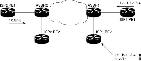
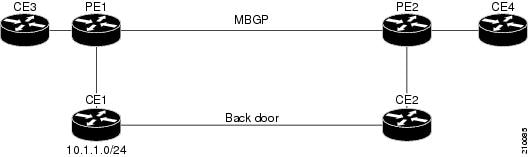
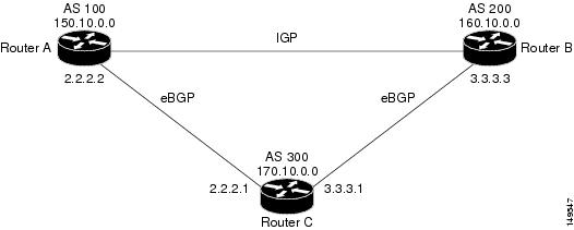
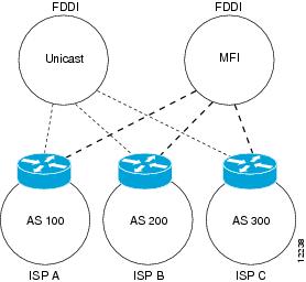
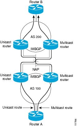
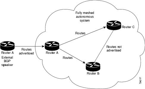
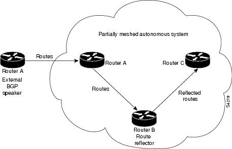
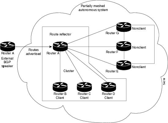
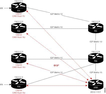
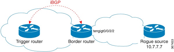
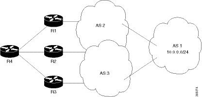
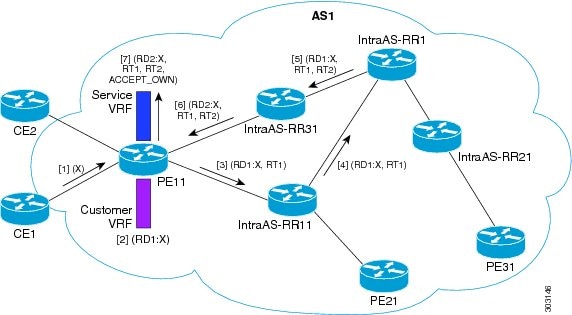

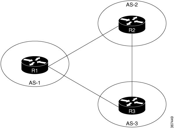

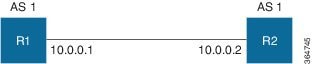
 Feedback