General Administration Guide on Cisco ASR 9000 Series Routers, Cisco IOS XR Releases
Bias-Free Language
The documentation set for this product strives to use bias-free language. For the purposes of this documentation set, bias-free is defined as language that does not imply discrimination based on age, disability, gender, racial identity, ethnic identity, sexual orientation, socioeconomic status, and intersectionality. Exceptions may be present in the documentation due to language that is hardcoded in the user interfaces of the product software, language used based on RFP documentation, or language that is used by a referenced third-party product. Learn more about how Cisco is using Inclusive Language.
OpenFlow is a specification developed by the Open Networking Foundation (ONF). It defines a flow-based forwarding model for
Ethernet switches (Layers 2–4) and provides a standardized protocol interface for programmatic control.
OpenFlow enables a centralized controller to manage the forwarding behavior of network switches via a secure channel. Through
this interface, the controller can
discover switch capabilities,
add or remove flow entries, and
request flow statistics
Note
OpenFlow does not handle local device configuration. This remains outside the scope of the protocol.
At its core, OpenFlow acts as a forwarding instruction set, allowing applications to program routing and switching behavior
directly. It supports flexible packet handling, including
arbitrary matching on packet header fields,
custom actions such as header rewriting, and
any-to-any routing and switching logic
Traditional routers and switches combine packet forwarding and routing decisions within the same device. These decisions are
typically governed by built-in protocols and control plane logic, with limited user configuration. In contrast, OpenFlow separates
control from forwarding, enabling more dynamic and programmable network behavior.
Key features
These are some of the key features of the OpenFlow Agent:
Flow-Based Forwarding: Implements a model that allows forwarding decisions based on flows rather than individual packets.
Standardized API: Defines a protocol that enables:
Learning switch capabilities
Adding and removing flow control entries
Requesting flow statistics
Controller Integration: Allows a controller to securely manage the forwarding behavior of a switch through a secure channel.
For details regarding OpenFlow, see the OpenFlow chapter in the System Management Configuration Guide for Cisco ASR 9000 Series Routers.
Prerequisites
These are the prerequisites required to configure OpenFlow agent on the platforms supporting IOS-XR.
Release 5.1.x software that has the OpenFlow functionality.
The Enhanced Ethernet line card for the Cisco ASR 9000 Series Router is required for the OpenFlow agent feature.
Any controller with version 1.1 or 1.3 is required, for example, POX, ODL.
The asr9k-k9sec Package Installation Envelope (PIE) must be present. The asr9k-mpls PIE is required for support on MPLS core
(such as, PWHE).
Limitations and guidelines for OpenFlow agent
These are some of the limitations you must be aware before configuring OpenFlow agent.
Same interface cannot be added to more than one logical OpenFlow switch.
No support for the output as an action for layer3 OpenFlow logical switch, such as pipeline131 and 132.
Only layer 3 interface support the NetFlow sampling statistics.
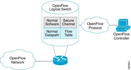
How does OpenFlow Agent work
The OpenFlow protocol is based on the Ethernet switch model. It uses an internal flow table and a standardized interface to
manage traffic flows by adding or removing flow entries. OpenFlow defines the communication channel between the OpenFlow Agent
on the switch and the OpenFlow controller on an external server. All network management functions are either integrated into
the controller or performed through it.
A physical switch can be segmented into multiple logical switches. This segmentation is configured using the CLI, where each
logical switch is associated with a specific controller connection and a set of enabled interfaces. The OpenFlow Agent software
manages these logical switches and facilitates communication with the controller.
Note
The OpenFlow Agent resides on the switch and is responsible for managing flow entries and interfacing with the controller.
The following figure illustrates the Cisco OpenFlow network architecture:
Figure 1. OpenFlow network architecture
Key Elements in the Cisco OpenFlow Architecture Diagram
OpenFlow Controller (External Server)
Resides outside the switch.
Manages flow entries and network behavior.
Communicates with the OpenFlow Agent via a secure channel.
OpenFlow Agent (On the Switch)
Embedded in the switch OS.
Interfaces with the controller to receive flow instructions.
Manages flow tables and applies actions to packets.
Logical Switches
A single physical switch is divided into multiple logical switches.
Each logical switch is configured via CLI and associated with a specific controller.
Interfaces are assigned to logical switches for traffic segmentation.
Flow Tables
Contain match-action rules.
Define how packets are processed (e.g., forward, drop, modify headers).
Secure Channel
TLS or TCP-based communication between the controller and the agent.
Ensures secure and reliable control traffic.
Data Plane vs. Control Plane
The data plane handles packet forwarding based on flow table rules.
The control plane (controller) makes high-level routing decisions.
This architecture enables centralized control and programmable network behavior, which is a core principle of Software Defined
Networking (SDN).
Note
Openflow for the Cisco ASR 9000 Series router functions in the Integrated Hybrid mode. In this mode, both Openflow and normal
switching and routing (for layer 3) operations such as L2 ethernet switching, L3 routing, etc are supported. Packets processed
as the Openflow forwarding path can be processed as a normal forwarding path.
OpenFlow table types
An OpenFlow flow table is a structured collection of flow entries, where each entry defines specific match criteria and associated
actions to be performed on matching packets. The capabilities of a flow table are determined by the types of match fields
and actions it supports, which may vary depending on the switch implementation.
Flow tables operate exclusively in the ingress direction, meaning they are applied only to incoming traffic. This behavior
is analogous to how a policy-map is applied in traditional networking. As such, OpenFlow matches and actions are evaluated
and executed solely on packets as they enter the switch.
In OpenFlow, a pipeline refers to a sequence of one or more flow tables arranged in a specific order. Each packet entering
the switch is processed through this ordered set of tables according to defined pipeline rules.
On the ASR 9000 (ASR9K) platform, the OpenFlow pipeline is limited to a single flow table. This means that all packet matching and action execution must occur within that single table, without the ability to chain
multiple tables as in more complex OpenFlow implementations.
VRF and global interfaces, BVI (ipv4 only), Bridge-domain, Gigabit ethernet, Bundle, Bundle-subinterfaces
Supports L3 (IPv4) header matches.
Supports L3 (IPv4) actions.
Can be applied to the ingress L3 interfaces.
L3_DS
132
VRF and global interfaces, BVI, Bridge-domain, Gigabit ethernet, Bundle, Bundle-subinterfaces
Supports L2 and L3 (IPv4/IPv6) header matches.
Supports L3 (IPv4/IPv6) actions.
Can be applied to the ingress L3 interfaces.
Packet-In and Packet-Out Feature
The Packet-In and Packet-Out feature enables communication between the OpenFlow Agent (logical switch) and the OpenFlow Controller. This mechanism allows
the agent to forward specific packets to the controller for processing or decision-making.
To achieve this, the flow entry is programmed with a special output action that uses the OFP_CONTROLLER port. When a packet matches such a flow, it is sent directly to the controller.
Additionally, this feature supports the standard OpenFlow output-to-port action. This action instructs the OpenFlow Agent to forward all packets matching a given flow to a designated physical or
logical port on the switch.
On-Demand Analytics with OpenFlow and NetFlow
Applications can be provided with on-demand analytics by using the OpenFlow protocol with NetFlow. NetFlow provides statistics
on packets flowing through the router, and is the standard for acquiring IP operational data from IP networks.
The following NetFlow maps must be configured:
Flow Exporter Map—Specifies the destination IP address of the NetFlow collector where the NetFlow Version 9 packets are sent.
Flow Monitor Map—Specifies the profile of the NetFlow producer, including the timeout values of active and inactive timers,
size of the NetfFow cache and the exporter to be used.
Sampler Map—Specifies how often Network Processor (NPU) needs to sample incoming and outgoing packets and create flow-packets
to punt to the Line Card (LC) Central Processing Unit (CPU).
The following parameters must be specified on the OpenFlow Agent logical switch:
Interface associated with the OpenFlow Agent logical switch that is enabled for NetFlow.
Flow Monitor Map
Sampler Map
Controller IP address
OpenFlow can be integrated with NetFlow to provide applications with on-demand traffic analytics. NetFlow is a widely adopted protocol for collecting IP traffic
statistics, offering detailed insights into packets traversing the router.
Enable NetFlow based analytics
To enable NetFlow-based analytics, the following NetFlow maps must be configured:
Flow Exporter Map: Defines the destination IP address of the NetFlow collector where NetFlow Version 9 packets are exported.
Flow Monitor Map: Specifies the characteristics of the NetFlow producer, including
active and inactive timeout values,
NetFlow cache size, and
associated Flow Exporter Map
Sampler Map: Determines the sampling rate for the Network Processor (NPU), indicating how frequently packets (incoming and
outgoing) are sampled and forwarded to the Line Card (LC) CPU for flow creation.
OpenFlow Agent configuration requirements
The following parameters must be specified on the OpenFlow Agent logical switch to enable NetFlow integration.
The interface associated with the OpenFlow Agent logical switch that is enabled for NetFlow
The configured Flow Monitor Map
The configured Sampler Map
The Controller IP address
OpenFlow Agent (OFA) on Cisco routers and switches
OpenFlow Software-Defined Networking (SDN) applications rely on network elements that support the standard OpenFlow protocol
and implement the OpenFlow switch model. On Cisco platforms, the OpenFlow Agent (OFA) operates as a local process that enables this functionality by providing the following capabilities:
Key Features of the OpenFlow Agent
OpenFlow Protocol Stack: Implements the standard OpenFlow protocol for communication with SDN controllers.
OpenFlow Switch Model: Abstracted from Cisco’s diverse hardware and software platforms.
Version and Feature Negotiation: Supports dynamic negotiation of OpenFlow versions and capabilities with controllers.
Local State and Statistics Aggregation: Collects and maintains flow and interface statistics locally.
Native CLI and Troubleshooting Tools: Offers dedicated command-line interface support for configuration and diagnostics.
High Availability: Designed for resilient operation in high-availability environments.
Functional components
The OpenFlow Agent supports the configuration of multiple controllers per logical switch. It can establish connections with up to eight controllers simultaneously, providing them access to the logical switch’s flow tables and interfaces. The agent receives flow entries
from the controllers and reports flow and interface statistics back to them.
For Layer 3 match conditions, Cisco extends the OpenFlow 1.0 and 1.3 protocols with a proprietary set-nexthop action to enable routing functionality.
OpenFlow Agent on Cisco ASR 9000 series routers
On the Cisco ASR 9000 platform, the OpenFlow Agent supports multiple logical switch instances. Each logical switch can manage
a set of physical or logical interfaces,
a Layer 2 bridge domain, or
a Virtual Routing and Forwarding (VRF) instance
Each logical switch can establish
a single OpenFlow connection to one controller, or
multiple connections to different controllers for redundancy
Connections to controllers use either plain TCP or TLS for secure communication.
Controller connection behavior
When a logical switch initiates a connection to a configured controller, the OpenFlow version is negotiated based on the supported
version bitmap on both the agent and the controller.
If a logical switch starts for the first time or loses connectivity with all controllers, it enters one of the following modes
based on configuration:
Fail-Secure Mode (default): Continues forwarding based on a predefined default rule.
Fail-Standalone Mode: Operates independently without controller input. This mode is enabled or disabled via CLI using the
fail-standalone option.
OpenFlow matches
Matches are supported on ingress port and various packet headers depending upon the packet type. Flows can have priorities.
Hence, the highest priority flow entry that matches the packet gets selected.
Following table shows the list of matches supported for various table types on Cisco ASR 9000 series routers
OpenFlow Matches
OpenFlow Switch Types Supported on ASR9K
Applied to L2 Bridge domain
Applied to L3 or L3 VRF interface
OXM Flow match field type for OpenFlow basic class
Description
L2 only
L2_L3
L3_V4
L3_DS
OFPXMT_OFB_IN_PORT
Switch input port
Yes
Yes
Yes
Yes
OFPXMT_OFB_IN_PHY_PORT
Switch physical port
No
No
No
No
OFPXMT_OFB_METADATA
Metadata passed between tables
No
No
No
No
OFPXMT_OFB_ETH_DST
Ethernet destination address
Yes
Yes
No
Yes
OFPXMT_OFB_ETH_SRC
Ethernet source address
Yes
Yes
No
Yes
OFPXMT_OFB_ETH_TYPE
Ethernet frame type
Yes
Yes
No
Yes
OFPXMT_OFB_VLAN_VID
VLAN ID
Yes
Yes
No
Yes
OFPXMT_OFB_VLAN_PCP
VLAN priority
Yes
Yes
No
Yes
OFPXMT_OFB_IP_DSCP
IP DSCP (6 bits in ToS field)
No
Yes
Yes
Yes
OFPXMT_OFB_IP_ECN
IP ECN (2 bits in ToS field)
No
No
No
No
OFPXMT_OFB_IP_PROTO
IP protocol
No
Yes
Yes
Yes
OFPXMT_OFB_IPV4_SRC
IPv4 source address
No
Yes
Yes
Yes
OFPXMT_OFB_IPV4_DST
IPv4 destination address
No
Yes
Yes
Yes
OFPXMT_OFB_TCP_SRC
TCP source port
No
Yes
Yes
Yes
OFPXMT_OFB_TCP_DST
TCP destination port
No
Yes
Yes
Yes
OFPXMT_OFB_UDP_SRC
UDP source port
No
Yes
Yes
Yes
OFPXMT_OFB_UDP_DST
UDP destination port
No
Yes
Yes
Yes
OFPXMT_OFB_SCTP_SRC
SCTP source port
No
Yes
Yes
Yes
OFPXMT_OFB_SCTP_DST
SCTP destination port
No
No
No
No
OFPXMT_OFB_ICMPV4_TYPE
ICMP type
No
No
No
No
OFPXMT_OFB_ICMPV4_CODE
ICMP code
No
No
No
No
OFPXMT_OFB_ARP_OP
ARP opcode
No
No
No
No
OFPXMT_OFB_ARP_SPA
ARP source IPv4 address
No
No
No
No
OFPXMT_OFB_ARP_TPA
ARP target IPv4 address
No
No
No
No
OFPXMT_OFB_ARP_SHA
ARP source hardware address
No
No
No
No
OFPXMT_OFB_ARP_THA
ARP target hardware address
No
No
No
No
OFPXMT_OFB_IPV6_SRC
IPv6 source address
No
Yes
No
Yes
OFPXMT_OFB_IPV6_DST
IPv6 destination address
No
Yes
No
Yes
OFPXMT_OFB_IPV6_FLABEL
IPv6 Flow Label
No
No
No
No
OFPXMT_OFB_ICMPV6_TYPE
ICMPv6 type
No
No
No
No
OFPXMT_OFB_ICMPV6_CODE
ICMPv6 code
No
No
No
No
OFPXMT_OFB_IPV6_ND_TARGET
Target address for ND
No
No
No
No
OFPXMT_OFB_IPV6_ND_SLL
Source link-layer for ND
No
No
No
No
OFPXMT_OFB_IPV6_ND_TLL
Target link-layer for ND
No
No
No
No
OFPXMT_OFB_MPLS_LABEL
MPLS label
No
No
No
No
OFPXMT_OFB_MPLS_TC
MPLS TC
No
No
No
No
OFPXMT_OFP_MPLS_BOS
MPLS BoS bit
No
No
No
No
OFPXMT_OFB_PBB_ISID
PBB I-SID
No
No
No
No
OFPXMT_OFB_TUNNEL_ID
Logical Port Metadata
No
No
No
No
OFPXMT_OFB_IPV6_EXTHDR
IPv6 Extension Header pseudo-field
No
No
No
No
OpenFlow actions
Packet forwarding and packet modification types of actions are supported. The lists of actions are always immediately applied
to the packet.
Note
Only “Apply-actions” instruction (OFPIT_APPLY_ACTIONS) of OpenFlow 1.3 is supported.
Pipeline processing instructions that allow packets to be sent to subsequent tables for further processing are not supported
in this release.
Group tables and Meter tables are not supported.
Following table shows the list of action types supported for various table types on Cisco ASR 9000 series routers
OpenFlow Actions
OpenFlow Switch Types Supported on ASR9K
Applied to L2 Bridge domain
Applied to L3 or L3 VRF interface
OXM Flow action field type for OpenFlow basic class
Description
L2 only
L2_L3
L3_V4
L3_DS
OFPAT_OUTPUT
Output to switch port.
Yes
Yes
No
No
OFPAT_COPY_TTL_OUT
Copy TTL "outwards"
No
No
No
No
OFPAT_COPY_TTL_IN
Copy TTL "inwards"
No
No
No
No
OFPAT_SET_MPLS_TTL
MPLS TTL
No
No
No
No
OFPAT_DEC_MPLS_TTL
Decrement MPLS TTL
No
No
No
No
OFPAT_PUSH_VLAN
Push a new VLAN tag
Yes
Yes
No
No
OFPAT_POP_VLAN
Pop the outer VLAN tag
Yes
Yes
No
No
OFPAT_PUSH_MPLS
Push a new MPLS tag
No
No
No
No
OFPAT_POP_MPLS
Pop the outer MPLS tag
No
No
No
No
OFPAT_SET_QUEUE
Set queue id when outputting to a port
No
No
No
No
OFPAT_GROUP
Apply group
No
No
No
No
OFPAT_SET_NW_TTL
IP TTL
No
No
No
No
OFPAT_DEC_NW_TTL
Decrement IP TTL
No
No
No
No
OFPAT_SET_FIELD
Set a header field using OXM TLV format
Yes
Yes
Yes
Yes
OFPAT_PUSH_PBB
Push a new PBB service tag (I-TAG)
No
No
No
No
OFPAT_POP_PBB
Pop the outer PBB service tag
No
No
No
No
Cisco extension actions
The set ipv4 or set ipv6 nexthop actions are used to redirect an ipv4 or ipv6 packet to the specified nexthop address, instead
of using the destination address in the packet. This provides ABF (ACL Based Forwarding) kind of functionality using OpenFlow.
However, VRF support and nexthop tracking as supported by CLI based ABF feature is not supported in this release.
The set fcid (Forward Class ID) action can be used to support PBTS (Policy Based Tunnel Selection) functionality using OpenFlow.
Following table shows the list of actions added by Cisco to support some extra features on Cisco ASR 9000 series routers.
Cisco proprietary actions
OpenFlow Switch Types Supported on ASR9K
Applied to L2 Bridge domain
Applied to L3 or L3 VRF interface
OXM Flow match field type for OpenFlow basic class
Description
L2 only
L2_L3
L3_V4
L3_DS
Set Ipv4 Nexthop
Set ipv4 nexthop address
No
No
Yes
Yes
Set Ipv6 Nexthop
Set ipv6 nexthop address
No
No
No
Yes
Set Forward Class ID
Set forward class ID
No
No
Yes
Yes
Set Field Actions
This table lists the set field actions supported by the Cisco ASR 9000 series router:
OpenFlow Matches
OpenFlow Switch Types Supported on ASR9K
Applied to L2 Bridge domain
Applied to L3 or L3 VRF interface
OXM Flow match field type for OpenFlow basic class
Description
L2 only
L2_L3
L3_V4
L3_DS
OFPXMT_OFB_ETH_DST
Ethernet destination address
Yes
Yes
No
No
OFPXMT_OFB_ETH_SRC
Ethernet source address
Yes
Yes
No
No
OFPXMT_OFB_ETH_TYPE
Ethernet frame type
No
No
No
No
OFPXMT_OFB_VLAN_VID
VLAN ID
Yes
Yes
No
No
OFPXMT_OFB_VLAN_PCP
VLAN priority
Yes
Yes
No
No
OFPXMT_OFB_IP_DSCP
IP DSCP (6 bits in ToS field)
No
No
Yes
Yes
OFPXMT_OFB_IP_ECN
IP ECN (2 bits in ToS field)
No
No
No
No
OFPXMT_OFB_IP_PROTO
IP protocol
No
No
No
No
OFPXMT_OFB_IPV4_SRC
IPv4 source address
No
No
Yes
Yes
OFPXMT_OFB_IPV4_DST
IPv4 destination address
No
No
Yes
Yes
OFPXMT_OFB_TCP_SRC
TCP source port
No
No
Yes
Yes
OFPXMT_OFB_TCP_DST
TCP destination port
No
No
Yes
Yes
OFPXMT_OFB_UDP_SRC
UDP source port
No
No
Yes
Yes
OFPXMT_OFB_UDP_DST
UDP destination port
No
No
Yes
Yes
OFPXMT_OFB_SCTP_SRC
SCTP source port
No
No
No
No
OFPXMT_OFB_SCTP_DST
SCTP destination port
No
No
No
No
OFPXMT_OFB_ICMPV4_TYPE
ICMP type
No
No
No
No
OFPXMT_OFB_ICMPV4_CODE
ICMP code
No
No
No
No
OFPXMT_OFB_ARP_OP
ARP opcode
No
No
No
No
OFPXMT_OFB_ARP_SPA
ARP source IPv4 address
No
No
No
No
OFPXMT_OFB_ARP_TPA
ARP target IPv4 address
No
No
No
No
OFPXMT_OFB_ARP_SHA
ARP source hardware address
No
No
No
No
OFPXMT_OFB_ARP_THA
ARP target hardware address
No
No
No
No
OFPXMT_OFB_IPV6_SRC
IPv6 source address
No
No
No
No
OFPXMT_OFB_IPV6_DST
IPv6 destination address
No
No
No
No
OFPXMT_OFB_IPV6_FLABEL
IPv6 Flow Label
No
No
No
No
OFPXMT_OFB_ICMPV6_TYPE
ICMPv6 type
No
No
No
No
OFPXMT_OFB_ICMPV6_CODE
ICMPv6 code
No
No
No
No
OFPXMT_OFB_IPV6_ND_TARGET
Target address for ND
No
No
No
No
OFPXMT_OFB_IPV6_ND_SLL
Source link-layer for ND
No
No
No
No
OFPXMT_OFB_IPV6_ND_TLL
Target link-layer for ND
No
No
No
No
OFPXMT_OFB_MPLS_LABEL
MPLS label
No
No
No
No
OFPXMT_OFB_MPLS_TC
MPLS TC
No
No
No
No
OFPXMT_OFP_MPLS_BOS
MPLS BoS bit
No
No
No
No
OFPXMT_OFB_PBB_ISID
PBB I-SID
No
No
No
No
OFPXMT_OFB_TUNNEL_ID
Logical Port Metadata
No
No
No
No
OFPXMT_OFB_IPV6_EXTHDR
IPv6 Extension Header pseudo-field
No
No
No
No
Configure OneP for OpenFlow
Purpose of this task is to configure OneP (One Platform Kit) for OpenFlow.
Before you begin
To configure OneP (One Platform Kit) for OpenFlow, it's important to note that OnePK support was discontinued starting with
Cisco IOS XR Release 5.3.4. Therefore, OneP is no longer used or supported for OpenFlow configuration.
Instead, you can configure OpenFlow directly through the OpenFlow Agent (OFA) using native CLI commands. This includes setting up logical switches, controller connections, flow tables, and optionally
integrating with NetFlow for analytics.
Procedure
Run the onep command to enter the OneP configuration submode. This is where you define the parameters related to the One Platform
Kit, which provides APIs for external applications to interact with the router.
Configure Layer 2_Layer 3 logical switch for the OpenFlow Agent
The purpose of this task is to enable centralized control and dynamic routing of both Layer 2 (switching) and Layer 3 (routing)
traffic by allowing the OpenFlow controller to manage a unified logical switch.
Procedure
Step 1
Run the following command to configure Layer 2_Layer 3 logical switch for the OpenFlow Agent
Repeat to configure another logical switch for the OpenFlow Agent.
Configure a Layer 3_VRF logical switch
The purpose of this task is to configure a Layer 3 VRF logical switch to enable the OpenFlow Agent to centrally manage routing
and traffic segmentation across virtual routing instances.
Procedure
Step 1
Run the following command to configure a Layer 3_VRF logical switch
Configure a Layer 3_dual-stack logical switch for the OpenFlow Agent
The purpose of this task is to configure a Layer 3 dual-stack logical switch to enable the OpenFlow agent to centrally manage
both IPv4 and IPv6 routing within a unified virtual network environment.
Procedure
Step 1
Run the following commands to configure a Layer 3_dual-stack logical switch
Repeat these steps to configure another logical switch for the OpenFlow Agent.
Enable Transport Layer Security (TSL)
The purpose of this task is to enable Transport Layer Security (TLS) to ensure secure, encrypted communication between network
components, protecting data integrity and confidentiality.
The purpose of this task is to configure NetFlow for the OpenFlow Agent to enable detailed traffic monitoring and flow analysis
for enhanced network visibility and performance management.
Procedure
Run the following commands to configure NetFlow for the OpenFlow Agent
Example:
Router# configure
Router(config)# flow exporter-map fem
Router(config-fem)# destination 10.0.1.2
Router(config-fem)# version v9
Router(config-fem-ver)# commit
Router(config-fem-ver)# exit
Router(config)# flow monitor-map mmap
Router(config-fmm)# record ipv4
Router(config-fmm)# exporter fmap
Router(config-fmm)# cache entries 4096
Router(config-fmm)# cache timeout active 10
Router(config-fmm)# commit
Router(config-fmm)# exit
Router(config)# sampler-map
Router(config-sm)# random 1 out-of 65535
Router(config-sm)# commit
Router(config-sm)# exit
Configuration Examples: Openflow
The purpose of the task is to view the configuration examples of OpenFlow.
Procedure
Step 1
Attaching a bridge domain to an Openflow Switch: Examples
Example:
Attaching a L2-only Openflow switch
openflow
switch 1 pipeline 129
  tls trust-point local tp1 remote tp1
  bridge-group SDN-2 bridge-domain OF-2
  controller ipv4 5.0.1.200 port 6653 security tls\


Attaching a L2_L3 Openflow switch
openflow
switch 1 pipeline 130
  tls trust-point local tp1 remote tp1
  bridge-group SDN-2 bridge-domain OF-2
  controller ipv4 5.0.1.200 port 6653 security tls

L3_V4 switch can be attached either to a VRF or directly to layer 3 interfaces under global VRF.
In case of VRF, all the interfaces in that VRF become part of the OpenFlow switch.
openflow
switch l1 pipeline 131
  vrf IPv4
  controller ipv4 5.0.1.200 port 6653 security none
 !


L3_DS switch can be attached either to a VRF or directly to layer 3 interfaces under global VRF.
openflow
switch l2 pipeline 132
  vrf IPv4
  controller ipv4 5.0.1.200 port 6653 security none
 !
Step 2
OpenFlow Agent with NetFlow Collection and Analytics Configuration: Example
Example:
The following example describes the NetFlow exporter map configuration for the OpenFlow logical switch.
Device> enable
Device# configure terminal
Device(config)# flow exporter-map fem
Device(config-fem)# destination 10.0.1.2
Device(config-fem)# version v9
Device(config-fem-ver)# commit
Device(config-fem-ver)# exit
The following example describes the NetFlow monitor map configuration for the OpenFlow logical switch.
The following example describes how the OpenFlow Agent logical switch is configured so that the NetFlow collection and analytics
are associated with it.
The following example describes show command output for an OpenFlow Agent logical switch that is configured with NetFlow collection and analytics.
Device# show openflow switch 100
Fri Jan 25 14:29:21.078 UTC

Logical Switch Context
         Id:                    100
         Switch type:           Netflow
         Layer:                 NONE
         Signal version:        Openflow 1.0
         Data plane:            secure
         Fallback:              normal
         Config state:          no-shutdown
         Working state:         enabled
         TLS version:           NONE
         TLS private key:       none:none
         TLS private key file:  NONE
         TLS certificate file:  NONE
         Controller:            10.0.1.2:6633, last alive ping: 2013-01-25 14:29:20
         Netflow Monitor:       mmap
         Netflow Sampler:       smap
         Loopback i/f:          <none>
         Loopback addr:         <none>
         Interfaces:
                GigabitEthernet0/1/0/6

Device# show openflow switch 100 flows
Fri Jan 25 14:29:24.787 UTC

Logical Openflow Switch [100]:
NXST_FLOW reply (xid=0x0):
cookie=0x0, duration=204.729s, table=0, n_packets=0, n_bytes=0, priority=500 actions=netflow

Switch flow count: 1

Device# show openflow switch 100 controllers
Fri Jan 25 14:29:28.660 UTC

Logical Openflow Switch [100]:
        Controller [tcp:10.0.1.2:6633]
           role                :  Other
           connected           :  Yes
           state               :  ACTIVE
           sec_since_connect   :  487
Step 3
Usecase for Layer2
The Scenario: Enterprise Data Center needs to perform data backup to multiple other backup sites based on the Traffic flow.
The Main DC is in Vlan 100 and Backup sites are at VLAN 1000,1001,1002. These Sites are interconnected through L2VPN.
The Solution: Openflow, we can match any Layer 2 header field (in this example we have taken priority bits) and steer the
traffic to go on any L2 interconnect and also rewrite the VLANs appropriately.
Step 4
Usecase for Layer3
The Scenario: Three different flows from 3 different sites connected to PE1 are trying to send 350 mbps of traffic each to
PE2. The bandwidth of the shortest link, Path-2 (between PE1 and PE2) is only 1 Gigabit. Hence Path-2 gets congested as soon
as the third site begins to send traffic.
The Solution: Openflow controller can be used to install rules on PE1:
Match on Flow 1 (destined to Video server) and redirect traffic to Path-2
Match on Flow 2 (destined to Web server) and redirect traffic to Path-1
Match on Flow 3 (destined to File transfer server) and redirect traffic to Path-3
The Inference: Effectively utilizing the network bandwidth by redirecting destination specific traffic using OpenFlow rules.

 Feedback