Installing VSM Cards in the Cisco ASR 9000 Series Router
This guide contains instructions for installing VSM cards in the Cisco ASR 9000 Series Aggregation Services Router.
Pre-Installation Information
This section contains information about the following topics:
- Product Numbers and Supported Platforms
- Router Hardware Installation
- Cisco IOS XR Software Release and Hardware Revision Requirements
- Related Documentation
Product Numbers and Supported Platforms
Table 1-1 lists the Cisco product number to which this publication applies, and the supported router platforms for the VSM card.
|
|
|
|
|---|---|---|
Cisco ASR 9010 Router, Cisco ASR 9006 Router, Cisco ASR 9904 Router, Cisco ASR 9912 Router, Cisco ASR 9922 Router |
Router Hardware Installation
For hardware installation and configuration information for the Cisco ASR 9000 Series Router, refer to the Cisco ASR 9000 Series Aggregation Services Router Installation Guide. The guide includes information on how to install, maintain, and replace router subsystems, such as cooling fans, power supplies, chassis backplanes, and so on.
Cisco IOS XR Software Release and Hardware Revision Requirements

Note![]() The A9K-VSM-500 is not supported on Cisco IOS XR 64-bit images.
The A9K-VSM-500 is not supported on Cisco IOS XR 64-bit images.
The VSM cards have certain Cisco IOS XR software requirements. Also, to ensure compatibility with the software, your VSM cards should have a specific hardware revision number. The number is printed on a label affixed to the component side of the card and is displayed by the show diag command.
Table 1-2 lists the hardware and software requirements for cards.
|
|
Part Number |
|
|
|---|---|---|---|
The show diag and show version commands display the current hardware configuration of the router, including the system software version that is currently loaded and running. For complete descriptions of show commands, refer to the command reference or configuration guide for the installed Cisco IOS XR release.
If the command displays indicate that the Cisco IOS XR software is a version earlier than you need, go to http://www.cisco.com/web/Cisco_IOS_XR_Software/index.html for information about how to upgrade Cisco IOS XR Software.
For software configuration information, refer to the Cisco IOS XR software configuration and command reference publications for the installed Cisco IOS XR release. Also refer to the Cisco IOS XR software release notes for additional information.
Related Documentation
This publication describes the basic installation of the Cisco ASR 9000 Virtualized Services Module (VSM) Card card. For complete configuration information, refer to the following publications:
- Cisco ASR 9000 Series Aggregation Services Router Hardware Installation Guide
- Cisco ASR 9000 Series Aggregation Services Router Getting Started Guide
- Cisco ASR 9000 Series Aggregation Services Router Regulatory Compliance and Safety Guide
- Cisco ASR 9000 Series Aggregation Services Router Interface and Hardware Component Configuration Guide
- Cisco ASR 9000 Seriess Aggregation Services Router CGv6 Configuration Guide
See the “Obtaining Documentation and Submitting a Service Request” for information on how to obtain these publications.
VSM Card Product Overview
The VSM card is the next generation service card that provides a virtualized platform on the Cisco ASR 9000 Series Aggregation Services Router. The VSM card allows Cisco and third-party services and applications to be hosted simultaneously on top of a virtualized hardware environment.
- Platform service infrastructure (SIM)—This sub-module provides the hardware infrastructure for connecting the services components to the rest of the platform. It consists of two NPUs connected to the backplane.
- Application Processor Module—This sub-module provides the hardware framework for running services on the VSM card. It consists of four CPUs that are connected in a four-socket configuration over the high speeds QPI bus. This allows software running on any of these CPU cores to access the memories and peripherals connected to any of the four CPUs. A hardware assist block is attached to each of the CPUs.
The VSM card has four 10 Gigabit Ethernet SFP+ module ports. Each SFP+ port on the VSM card has an adjacent Link LED visible on the front panel that indicates the status of the associated SFP+ port.
The VSM card has the following guidelines and limitations:
- The VSM card is supported in any slot on the Cisco ASR 9000 Series Aggregation Services Router (ASR90xx and ASR99xx).
- There is no limit on the number of VSM cards that can be installed in the chassis at any one time.
- Traffic from satellite nV access interfaces can be redirected to the VSM card, and vice-versa.
- By default, there is no default VM application installed on the VSM card.
- The VSM card is not supported on the Cisco Aggregation Services Router ASR9001 Router.
- The VSM card is supported with the Cisco ASR 9000 Series Route Switch Processor 440, Cisco ASR 9000 Series Route Switch Processor 880, or later installed in the router. The VSM card is not supported with RSP2 installed in the router.
- The VSM card and Cisco ASR9000 ISM (Integrated Service Module) line card can operate simultaneously in the Cisco ASR 9000 Series Aggregation Services Router.
- The four 10 Gigabit Ethernet SFP+ module ports and their associated LEDS on the VSM card are not supported in the current release.
The VSM card is shown in Figure 1-1.
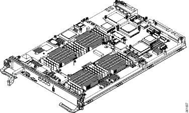
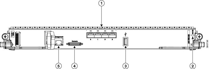
Figure 1-2 shows the front panel on the VSM card.
|
|
Four 10 Gigabit Ethernet SFP+ module ports and LEDs (not supported in current release) |
|
|
|
|
|
||
|
|
|
Preparing for Installation
The following sections provide information about preparing to install a VSM card:
Safety Guidelines
Before you perform any procedure in this publication, review the safety guidelines in this section to avoid injuring yourself or damaging the equipment.
The following guidelines are for your safety and to protect equipment. The guidelines do not include all hazards. Be alert.
Note![]() Before installing, configuring, or maintaining a card, review the safety warnings listed in the Cisco ASR 9000 Series Aggregation Services Router Regulatory Compliance and Safety Information publication that accompanied your router.
Before installing, configuring, or maintaining a card, review the safety warnings listed in the Cisco ASR 9000 Series Aggregation Services Router Regulatory Compliance and Safety Information publication that accompanied your router.
- Keep the work area clear and dust free during and after installation. Do not allow dirt or debris to enter into any laser-based components.
- Do not wear loose clothing, jewelry, or other items that could get caught in the router while working with cards.
- Cisco equipment operates safely when it is used in accordance with its specifications and product usage instructions.

Preventing Electrostatic Discharge
Electrostatic discharge (ESD) damage, which can occur when electronic cards or components are improperly handled, results in complete or intermittent failures. Electromagnetic interference (EMI) shielding is an integral component of the VSM card. Cisco recommends using an ESD-preventive strap whenever you are handling network equipment or one of its components.
The following are guidelines for preventing ESD damage:
- Always use an ESD-preventive wrist or ankle strap and ensure that it makes good skin contact. Connect the equipment end of the connection cord to an ESD connection socket on the router or to bare metal on the chassis.
- Avoid touching card circuit boards or connector pins. When sliding cards in or out of slots, you should handle them only by the faceplate or metal card carrier.
- When carrying a card, carry it only by the metal card carrier or inside a static shielding bag.
- Place removed cards component-side-up on an antistatic surface or in a static shielding bag. If you plan to return the component to the factory, immediately place it in a static shielding bag.
- Avoid contact between the cards and clothing. The wrist strap only protects the board from ESD voltages on the body; ESD voltages on clothing can still cause damage.
Required Tools and Equipment
You need the following tools and parts to remove and install VSM cards:
Note![]() If you need additional equipment, see Cisco.com or your service representative for ordering information.
If you need additional equipment, see Cisco.com or your service representative for ordering information.
Removing and Installing a VSM Card
The following sections provide procedures for removing or installing a VSM card:
- Handling a VSM Card
- Guidelines for VSM Card Removal and Installation
- Removing a Card
- Installing a VSM Card
Note![]() See “Guidelines for VSM Card Removal and Installation” before removing a VSM card while power to the router is on.
See “Guidelines for VSM Card Removal and Installation” before removing a VSM card while power to the router is on.
Handling a VSM Card
Each VSM card circuit board is mounted to a metal carrier and is sensitive to electrostatic discharge (ESD) damage. Before you begin installation, read “Preparing for Installation” for a list of parts and tools required for installation.
When a slot is not in use, a blank must fill the empty slot to allow the router to conform to electromagnetic interference (EMI) emissions requirements and to allow proper airflow across the installed modules. If you plan to install a VSM card in a slot that is not in use, you must first remove the blank.
Guidelines for VSM Card Removal and Installation
Guidelines for card removal and installation include the following:
- Online insertion and removal (OIR) is supported, enabling you to remove and install VSM cards while the router is operating. OIR is seamless to users on the network, maintains all routing information, and ensures session preservation. However, you must power down a VSM card prior to removing it from the chassis.
Note![]() To avoid solid state disk failures, it is mandatory to power down the VSM card before OIR.
To avoid solid state disk failures, it is mandatory to power down the VSM card before OIR.
- To power down the VSM card, use the hw-module power disable command in administration configuration mode. To power up the VSM card after OIR, use the no form of this command. The example below shows how to power down the VSM card installed in slot 0:
After removing and inserting a card into the same slot, allow at least 60 seconds before removing or inserting another card.
- Cards have two ejector levers to release the card from its backplane connector. Use the levers when you are removing the card and to seat the card firmly in its backplane connector when you are installing the card. The ejector levers align and seat the card connectors in the backplane.
When you install a card, always use the ejector levers to ensure that the card is correctly aligned with the backplane connector; the connector pins should make contact with the backplane in the correct order, indicating that the card is fully seated in the backplane. If a card is only partially seated in the backplane, the router will hang and subsequently crash.
Removing a Card
If you are migrating from a line card to a VSM card or replacing a failed VSM card, you must first remove the existing card and then install the new VSM card in the same slot. To remove a line card or VSM card, follow these steps:
Step 1![]() Attach an ESD-preventive wrist or ankle strap and follow its instructions for use.
Attach an ESD-preventive wrist or ankle strap and follow its instructions for use.
Step 2![]() Disconnect and remove all interface cables from the ports; note the current connections of the cables to the ports on the card.
Disconnect and remove all interface cables from the ports; note the current connections of the cables to the ports on the card.
Step 3![]() Detach the card cable-management bracket from the card.
Detach the card cable-management bracket from the card.
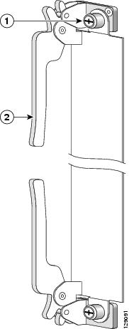
Step 4![]() Use a screwdriver to loosen the captive screw at each end of the card faceplate.
Use a screwdriver to loosen the captive screw at each end of the card faceplate.
Step 5![]() Simultaneously pivot the ejector levers away from each other to release the card from the backplane connector.
Simultaneously pivot the ejector levers away from each other to release the card from the backplane connector.
Figure 1-3 Ejector Levers and Captive Screws
|
|
|
Step 6![]() Grasp the ejector levers and pull the card halfway out of the slot.
Grasp the ejector levers and pull the card halfway out of the slot.
Step 7![]() Grasp the card and gently pull it straight out of the slot, keeping your other hand under the card to guide it. Avoid touching the card printed circuit board, components, or any connector pins.
Grasp the card and gently pull it straight out of the slot, keeping your other hand under the card to guide it. Avoid touching the card printed circuit board, components, or any connector pins.
Step 8![]() Place the removed card on an antistatic mat, or immediately place it in an antistatic bag if you plan to return it to the factory.
Place the removed card on an antistatic mat, or immediately place it in an antistatic bag if you plan to return it to the factory.
Step 9![]() If the card slot is to remain empty, install a line card blank (Product Number A9K-LC-FILR) to keep dust out of the chassis and to maintain proper airflow through the line card compartment. Secure the line card blank to the chassis by tightening its captive screws.
If the card slot is to remain empty, install a line card blank (Product Number A9K-LC-FILR) to keep dust out of the chassis and to maintain proper airflow through the line card compartment. Secure the line card blank to the chassis by tightening its captive screws.
Note![]() Always insert a dust plug in an optical port opening for each port that is not in use.
Always insert a dust plug in an optical port opening for each port that is not in use.
Installing a VSM Card
A VSM card slides into any available line card slot and connects directly to the backplane. If you are installing a new VSM card, you must first remove the line card blank from the available slot.
Note![]() Refer to the installation and configuration guide for your router for information on line card slot types, slot width, and slot location.
Refer to the installation and configuration guide for your router for information on line card slot types, slot width, and slot location.
To install a VSM card, follow these steps:
Step 1![]() Attach an ESD-preventive wrist or ankle strap and follow its instructions for use.
Attach an ESD-preventive wrist or ankle strap and follow its instructions for use.
Step 2![]() Choose an available line card slot for the VSM card, and verify that the card interface cable is long enough for you to connect the VSM card with any external equipment.
Choose an available line card slot for the VSM card, and verify that the card interface cable is long enough for you to connect the VSM card with any external equipment.
Step 3![]() Grasp the faceplate of the VSM card with one hand and place your other hand under the metal card carrier to support the weight of the card (see Figure 1-4). Position the VSM card for insertion into the line card cage slot. Avoid touching the VSM card printed circuit board, components, or any connector pins.
Grasp the faceplate of the VSM card with one hand and place your other hand under the metal card carrier to support the weight of the card (see Figure 1-4). Position the VSM card for insertion into the line card cage slot. Avoid touching the VSM card printed circuit board, components, or any connector pins.
Step 4![]() Carefully slide the VSM card into the slot until the ejector levers make contact with the edges of the card cage, then stop when the ejector lever hooks catch the lip of the card cage. If they do not catch, try reinserting the VSM card until the ejector levers are fully latched.
Carefully slide the VSM card into the slot until the ejector levers make contact with the edges of the card cage, then stop when the ejector lever hooks catch the lip of the card cage. If they do not catch, try reinserting the VSM card until the ejector levers are fully latched.
Step 5![]() Simultaneously pivot both ejector levers toward each other until they are perpendicular to the VSM card faceplate. This action firmly seats the card in the backplane. See Figure 1-4.
Simultaneously pivot both ejector levers toward each other until they are perpendicular to the VSM card faceplate. This action firmly seats the card in the backplane. See Figure 1-4.
Step 6![]() Tighten the captive screw on each end of the VSM card faceplate to ensure proper EMI shielding and to prevent the VSM card from becoming partially dislodged from the backplane. Tighten the captive screws to a torque of 10 +/–1 in-lb. See Figure 1-4.
Tighten the captive screw on each end of the VSM card faceplate to ensure proper EMI shielding and to prevent the VSM card from becoming partially dislodged from the backplane. Tighten the captive screws to a torque of 10 +/–1 in-lb. See Figure 1-4.
Figure 1-4 VSM Card Ejector Lever Positions During Installation
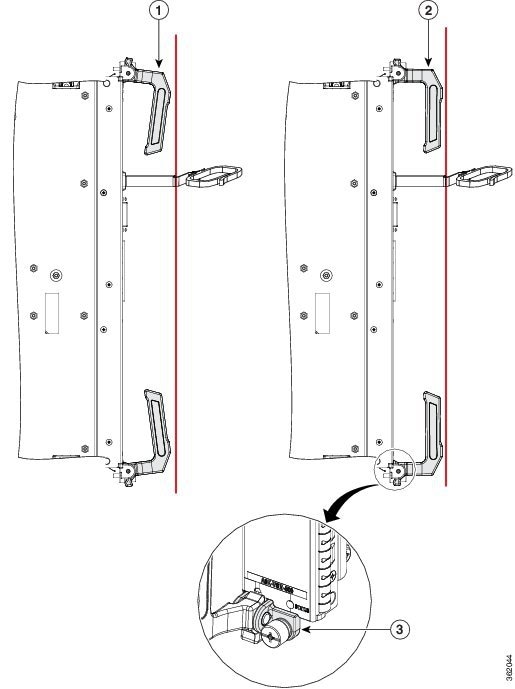
| Note: Vertical red lines in Figure 1-4 indicate a line fully parallel to the VSM card front panel. |
|||||
|
|
Slightly loose position of ejector levers when the VSM card is fully seated in the backplane, but the captive installation screws are not fully tightened |
|
Fully parallel position of ejector levers when the VSM card is fully seated in the backplane and captive installation screws are fully tightened |
|
Slight gap that may be present when the VSM card is fully seated in the backplane and captive installation screws are fully tightened |
Checking the Installation
This section describes the procedures you can use to verify the VSM card installation and includes information on the following topics:
Verifying the Installation
This section describes how to verify the VSM card installation by observing the VSM card LED states and the information displayed on the console terminal. See the “Status LEDs” section for detailed information about the status LEDs on the VSM card.
When the system has reinitialized all interfaces, the VSM card STATUS LED should be green (on). The console screen also displays a message as the system discovers each interface during its reinitialization.
Use the following procedure to verify that a VSM card is installed correctly:
Step 1![]() Observe the console display messages and verify that the system discovers the VSM card, while the system reinitializes each interface, as follows:
Observe the console display messages and verify that the system discovers the VSM card, while the system reinitializes each interface, as follows:
- As a VSM card is initialized, the STATUS LED will first be amber, indicating that power is on, but the VSM card is being configured. When the VSM card is active, the STATUS LED will illuminate green.
Step 2![]() When the VSM card STATUS LED is green, all associated interfaces are configurable.
When the VSM card STATUS LED is green, all associated interfaces are configurable.
- If a VSM card is replaced with a VSM card of the same type (as in an OIR or hardware swap), the previous configuration is reinstated when the VSM card becomes active.
- If a VSM card has not been previously installed in the same slot, then the configuration for all associated interfaces is empty. New interfaces are not available until you configure them.
Step 3![]() If the VSM card has not become active, refer to the system console messages. If there is no indication that an upgrade is underway, see “Verifying and Troubleshooting the VSM Card Installation” .
If the VSM card has not become active, refer to the system console messages. If there is no indication that an upgrade is underway, see “Verifying and Troubleshooting the VSM Card Installation” .
Using show Commands to Verify VSM Card Status
The following procedure uses show commands to verify that the new VSM card is installed correctly and operating correctly.
Step 1![]() Use the show running-config command to display the system configuration.
Use the show running-config command to display the system configuration.
Step 2![]() Display information about the installed VSM cards using the show diag command.
Display information about the installed VSM cards using the show diag command.
Step 3![]() Use the show hw-module fpd location <rack/slot/subslot> command to verify the FPD version information of the VSM card installed in the system. The hw-module fpd location <rack/slot/subslot> command can be used for upgrading the FPD version on the installed VSM cards.
Use the show hw-module fpd location <rack/slot/subslot> command to verify the FPD version information of the VSM card installed in the system. The hw-module fpd location <rack/slot/subslot> command can be used for upgrading the FPD version on the installed VSM cards.
Note![]() If a VSM card does not meet the minimum version required, the FPD may need to be updated. Refer to Cisco ASR 9000 Series Aggregation Services Router System Management Configuration Guide for instructions.
If a VSM card does not meet the minimum version required, the FPD may need to be updated. Refer to Cisco ASR 9000 Series Aggregation Services Router System Management Configuration Guide for instructions.
Step 4![]() Use the show platform command to check the state of all the boards in the chassis, including the VSM card.
Use the show platform command to check the state of all the boards in the chassis, including the VSM card.
The VSM card state should be “IOS XR RUN” in the show platform command output.
Step 5![]() Finally, you can use the show version command to obtain software version information for the installed VSM cards.
Finally, you can use the show version command to obtain software version information for the installed VSM cards.
Table 1-3 describes the show commands you can use to display VSM card information.
For complete descriptions of show commands, refer to the command reference or configuration guide for the installed Cisco IOS XR release.
Use the following procedure to verify that the VSM card is installed correctly:
Step 1![]() Observe the console display messages and verify that the system discovers the VSM card.
Observe the console display messages and verify that the system discovers the VSM card.
Step 2![]() Verify that the STATUS LED on the VSM card goes on (is green) and remains on after the reinitialization is complete. If the STATUS LED remains on, proceed to Step 5. If the STATUS LED does not remain on, proceed to Step 3.
Verify that the STATUS LED on the VSM card goes on (is green) and remains on after the reinitialization is complete. If the STATUS LED remains on, proceed to Step 5. If the STATUS LED does not remain on, proceed to Step 3.
Step 3![]() If the STATUS LED on a VSM card fails to go on, the VSM card might not be fully seated.
If the STATUS LED on a VSM card fails to go on, the VSM card might not be fully seated.
2.![]() Inspect the VSM card. Verify there are no bent pins or parts and that there is nothing lodged in the devices that could prevent a good connection.
Inspect the VSM card. Verify there are no bent pins or parts and that there is nothing lodged in the devices that could prevent a good connection.
3.![]() Re-insert the VSM card in the router.
Re-insert the VSM card in the router.
4.![]() After the system reinitialization, the STATUS LED on the VSM card should go on and remain on. If the STATUS LED remains on, proceed to Step 5. If it does not, try reseating the VSM card in another available slot on the router. Wait for the STATUS LED on the VSM card to turn green.
After the system reinitialization, the STATUS LED on the VSM card should go on and remain on. If the STATUS LED remains on, proceed to Step 5. If it does not, try reseating the VSM card in another available slot on the router. Wait for the STATUS LED on the VSM card to turn green.
5.![]() If the STATUS LED goes on, suspect a failed backplane port in the original slot.
If the STATUS LED goes on, suspect a failed backplane port in the original slot.
6.![]() If the STATUS LED fails to go on, remove the VSM card and reinstall it accordingly.
If the STATUS LED fails to go on, remove the VSM card and reinstall it accordingly.
7.![]() If no LEDs on the VSM card go on, suspect a faulty VSM card. Contact a service representative to report the problem and obtain further instructions.
If no LEDs on the VSM card go on, suspect a faulty VSM card. Contact a service representative to report the problem and obtain further instructions.
Step 4![]() If the VSM card is new and is not a replacement, configure the new VSM card using the instructions in Cisco IOS XR Getting Started Guide for the Cisco ASR 9000 Series Router and Cisco ASR 9000 Series Aggregation Services Router Interface and Hardware Component Configuration Guide.
If the VSM card is new and is not a replacement, configure the new VSM card using the instructions in Cisco IOS XR Getting Started Guide for the Cisco ASR 9000 Series Router and Cisco ASR 9000 Series Aggregation Services Router Interface and Hardware Component Configuration Guide.
Step 5![]() Repeat Step 1 through Step 4 to verify that any additional VSM cards are properly installed.
Repeat Step 1 through Step 4 to verify that any additional VSM cards are properly installed.
 Feedback