Installing and Removing the SFP and XFP Modules
This chapter describes how to install and remove small form-factor pluggables (SFP modules or XFP modules) on the Cisco ASR 1000 Series Fixed Ethernet Line Card. This chapter contains the following sections:
Removing and Installing SFP Modules

Note![]() The Cisco ASR 1000 Series Fixed Ethernet Line Card will accept only the SFP modules listed as supported in this document. An SFP check is run every time an SFP module is inserted into a Cisco ASR 1000 Series Fixed Ethernet Line Card, and only those SFP modules that pass this check are usable.
The Cisco ASR 1000 Series Fixed Ethernet Line Card will accept only the SFP modules listed as supported in this document. An SFP check is run every time an SFP module is inserted into a Cisco ASR 1000 Series Fixed Ethernet Line Card, and only those SFP modules that pass this check are usable.
Before you remove or install an SFP module, read the installation information provided in this section and the “Laser and LED Safety” section.

Removing and inserting an SFP module can shorten its useful life. Therefore, you should not remove and insert SFP modules unless it is absolutely necessary.
SFP modules use one of four different latching devices to install and remove the module from a port. The four types of SFP module-latching devices are described in the following sections:
Bale Clasp SFP Module
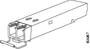
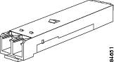
The bale clasp SFP module has a clasp that you should use to remove or install the SFP module. (See Figure 5-1.)
Figure 5-1 Bale Clasp SFP Module
Removing a Bale Clasp SFP Module
To remove this type of SFP module, follow these steps:
Step 1![]() Attach an ESD-preventive wrist strap or ankle strap by following the instructions provided.
Attach an ESD-preventive wrist strap or ankle strap by following the instructions provided.
Step 2![]() Disconnect and remove all the interface cables from the ports and note the current connections of the cables to the ports on the line card.
Disconnect and remove all the interface cables from the ports and note the current connections of the cables to the ports on the line card.
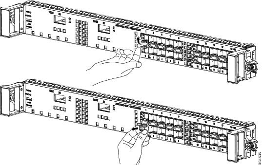
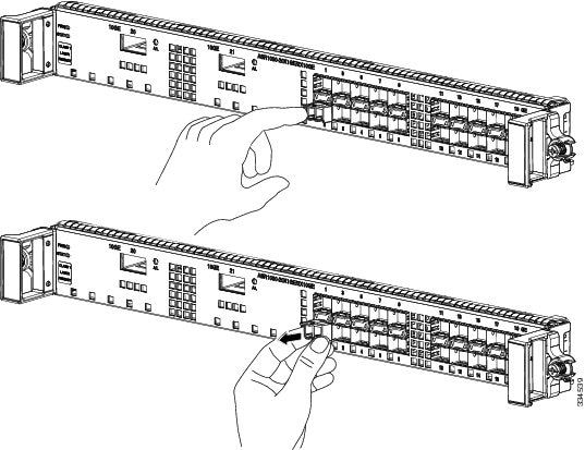
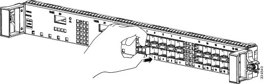
Step 3![]() Open the bale clasp on the SFP module with your index finger in a downward direction, as shown in Figure 5-2. If the bale clasp is obstructed and you cannot use your index finger to open it, use a small flat-blade screwdriver to open the bale clasp.
Open the bale clasp on the SFP module with your index finger in a downward direction, as shown in Figure 5-2. If the bale clasp is obstructed and you cannot use your index finger to open it, use a small flat-blade screwdriver to open the bale clasp.
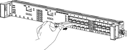
Step 4![]() Grasp the SFP module between your thumb and index finger and carefully remove it from the port as shown in Figure 5-2.
Grasp the SFP module between your thumb and index finger and carefully remove it from the port as shown in Figure 5-2.
Figure 5-2 Removing a Bale Clasp SFP Module
Step 5![]() Place the removed SFP module on an antistatic mat, or immediately place it in a static shielding bag if you plan to return it to the factory.
Place the removed SFP module on an antistatic mat, or immediately place it in a static shielding bag if you plan to return it to the factory.
Step 6![]() Protect your line card by inserting clean SFP module cage covers into the optical module cage when no SFP modules are installed.
Protect your line card by inserting clean SFP module cage covers into the optical module cage when no SFP modules are installed.
Installing a Bale Clasp SFP Module
To install this type of SFP module, follow these steps:
Step 1![]() Attach an ESD-preventive wrist strap or ankle strap according to the instructions provided.
Attach an ESD-preventive wrist strap or ankle strap according to the instructions provided.
Step 2![]() Close the bale clasp before inserting the SFP module.
Close the bale clasp before inserting the SFP module.
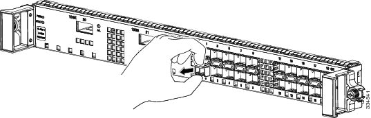
Step 3![]() Line up the SFP module with the port, and slide it into the port. (See Figure 5-3.)
Line up the SFP module with the port, and slide it into the port. (See Figure 5-3.)
Figure 5-3 Installing a Bale Clasp SFP Module into a Port
Note![]() Verify that the SFP modules are completely seated and secured in their assigned receptacles on the line card by firmly pushing on each SFP module. If the SFP module is not completely seated and secured in the receptacle, you will hear a click as the triangular pin at the bottom of the SFP module snaps into the hole in the receptacle.
Verify that the SFP modules are completely seated and secured in their assigned receptacles on the line card by firmly pushing on each SFP module. If the SFP module is not completely seated and secured in the receptacle, you will hear a click as the triangular pin at the bottom of the SFP module snaps into the hole in the receptacle.
Mylar Tab SFP Module
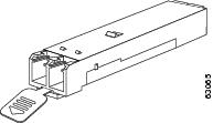
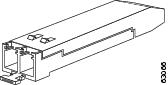
The mylar tab SFP module has a tab that you pull to remove the module from a port. (See Figure 5-4.)
Figure 5-4 Mylar Tab SFP Module
Removing a Mylar Tab SFP Module
To remove this type of SFP module, follow these steps:
Step 1![]() Attach an ESD-preventive wrist strap or ankle strap according to the instructions provided.
Attach an ESD-preventive wrist strap or ankle strap according to the instructions provided.
Step 2![]() Disconnect and remove all the interface cables from the ports; note the current connections of the cables to the ports on the line card.
Disconnect and remove all the interface cables from the ports; note the current connections of the cables to the ports on the line card.
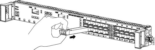
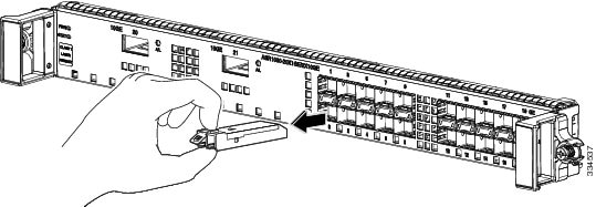
Step 3![]() Pull the tab gently in a slightly downward direction until it disengages from the port and then pull the SFP module out. (See Figure 5-5.)
Pull the tab gently in a slightly downward direction until it disengages from the port and then pull the SFP module out. (See Figure 5-5.)
Figure 5-5 Removing a Mylar Tab SFP Module
Step 4![]() Place the removed SFP module on an antistatic mat, or immediately place it in a static shielding bag if you plan to return it to the factory.
Place the removed SFP module on an antistatic mat, or immediately place it in a static shielding bag if you plan to return it to the factory.
Step 5![]() Protect your line card by inserting clean SFP module cage covers on the optical module cage when there is no SFP module installed.
Protect your line card by inserting clean SFP module cage covers on the optical module cage when there is no SFP module installed.
Installing a Mylar Tab SFP Module
To install this type of SFP module, follow these steps:
Step 1![]() Attach an ESD-preventive wrist strap or ankle strap according to the instructions provided.
Attach an ESD-preventive wrist strap or ankle strap according to the instructions provided.
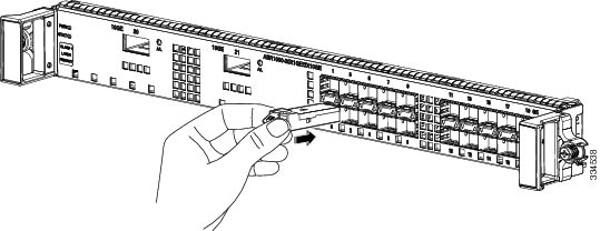
Step 2![]() Line up the SFP module with the port, and slide it into place. (See Figure 5-6.)
Line up the SFP module with the port, and slide it into place. (See Figure 5-6.)
Figure 5-6 Installing a Mylar Tab SFP Module
Note![]() Verify that the SFP modules are completely seated and secured in their assigned receptacles on the line card by firmly pushing on each SFP module. If the SFP module is not completely seated and secured in the receptacle, you will hear a click as the triangular pin at the bottom of the SFP module snaps into the hole in the receptacle.
Verify that the SFP modules are completely seated and secured in their assigned receptacles on the line card by firmly pushing on each SFP module. If the SFP module is not completely seated and secured in the receptacle, you will hear a click as the triangular pin at the bottom of the SFP module snaps into the hole in the receptacle.
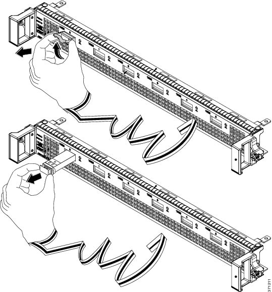
Actuator Button SFP Module
The actuator button SFP module includes a button that you should push in order to remove the SFP module from a port. (See Figure 5-7.)
Figure 5-7 Actuator Button SFP Module
Removing an Actuator Button SFP Module
To remove this type of SFP module, follow these steps:
Step 1![]() Attach an ESD-preventive wrist strap or ankle strap according to the instructions provided.
Attach an ESD-preventive wrist strap or ankle strap according to the instructions provided.
Step 2![]() Disconnect and remove all the interface cables from the ports; note the current connections of the cables to the ports on the line card.
Disconnect and remove all the interface cables from the ports; note the current connections of the cables to the ports on the line card.
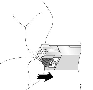
Step 3![]() Gently press the actuator button on the front of the SFP module until it clicks and the latch mechanism is activated, releasing the SFP module from the port. (See Figure 5-8.)
Gently press the actuator button on the front of the SFP module until it clicks and the latch mechanism is activated, releasing the SFP module from the port. (See Figure 5-8.)
Figure 5-8 Removing an Actuator Button SFP Module from a Port
Step 4![]() Grasp the actuator button between your thumb and index finger and carefully pull the SFP module from the port.
Grasp the actuator button between your thumb and index finger and carefully pull the SFP module from the port.
Step 5![]() Place the removed SFP module on an antistatic mat, or immediately place it in a static shielding bag if you plan to return it to the factory.
Place the removed SFP module on an antistatic mat, or immediately place it in a static shielding bag if you plan to return it to the factory.
Step 6![]() Protect your line card by inserting clean SFP module cage covers on the optical module cage when there is no SFP module installed.
Protect your line card by inserting clean SFP module cage covers on the optical module cage when there is no SFP module installed.
Installing an Actuator Button SFP Module
To install this type of SFP module, follow these steps:
Step 1![]() Attach an ESD-preventive wrist strap or ankle strap according to the instructions provided.
Attach an ESD-preventive wrist strap or ankle strap according to the instructions provided.
Step 2![]() Line up the SFP module with the port and slide it in until the actuator button clicks into place. (See Figure 5-9.) Do not press the actuator button as you insert the SFP module because you might inadvertently disengage the SFP module from the port.
Line up the SFP module with the port and slide it in until the actuator button clicks into place. (See Figure 5-9.) Do not press the actuator button as you insert the SFP module because you might inadvertently disengage the SFP module from the port.
Figure 5-9 Installing an Actuator Button SFP Module
Note![]() Verify that the SFP modules are completely seated and secured in their assigned receptacles on the line card by firmly pushing on each SFP module. If the SFP module is not completely seated and secured in the receptacle, you will hear a click as the triangular pin at the bottom of the SFP module snaps into the hole in the receptacle.
Verify that the SFP modules are completely seated and secured in their assigned receptacles on the line card by firmly pushing on each SFP module. If the SFP module is not completely seated and secured in the receptacle, you will hear a click as the triangular pin at the bottom of the SFP module snaps into the hole in the receptacle.
Slide Tab SFP Module
The slide tab SFP module has a tab underneath the front of the SFP module. Use the tab to disengage the module from a port. (See Figure 5-10.)
Figure 5-10 Slide Tab SFP Module
Removing a Slide Tab SFP Module
To remove this type of SFP module, follow these steps:
Step 1![]() Attach an ESD-preventive wrist strap or ankle strap according to the instructions provided.
Attach an ESD-preventive wrist strap or ankle strap according to the instructions provided.
Step 2![]() Disconnect and remove all the interface cables from the ports; note the current connections of the cables to the ports on the line card.
Disconnect and remove all the interface cables from the ports; note the current connections of the cables to the ports on the line card.
Step 3![]() Grasp the SFP module between your thumb and index finger.
Grasp the SFP module between your thumb and index finger.
Step 4![]() With your thumb, push the slide tab at the bottom front of the SFP module in the direction of the line card to disengage the module from the line card port. (See Figure 5-11.)
With your thumb, push the slide tab at the bottom front of the SFP module in the direction of the line card to disengage the module from the line card port. (See Figure 5-11.)
Figure 5-11 Disengaging the Slide Tab
Step 5![]() With the tab still pushed, carefully pull the SFP module from the port, as shown in Figure 5-12.
With the tab still pushed, carefully pull the SFP module from the port, as shown in Figure 5-12.
Figure 5-12 Removing a Slide Tab SFP Module
Step 6![]() Place the removed SFP module on an antistatic mat, or immediately place it in a static shielding bag if you plan to return it to the factory.
Place the removed SFP module on an antistatic mat, or immediately place it in a static shielding bag if you plan to return it to the factory.
Step 7![]() Protect your line card by inserting clean SFP module cage covers on the optical module cage when there is no SFP module installed.
Protect your line card by inserting clean SFP module cage covers on the optical module cage when there is no SFP module installed.
Installing a Slide Tab SFP Module
To install this type of SFP module, follow these steps:
Step 1![]() Attach an ESD-preventive wrist strap or ankle strap according to the instructions provided.
Attach an ESD-preventive wrist strap or ankle strap according to the instructions provided.
Step 2![]() Hold the SFP module with the hardware label facing up.
Hold the SFP module with the hardware label facing up.
Step 3![]() Insert the SFP module into the appropriate slot and gently push on it until it snaps into the slot tightly. (See Figure 5-13.)
Insert the SFP module into the appropriate slot and gently push on it until it snaps into the slot tightly. (See Figure 5-13.)
Figure 5-13 Installing a Slide Tab SFP Module
Note![]() Verify that the SFP modules are completely seated and secured in their assigned receptacles on the line card by firmly pushing on each SFP module. If the SFP module is not completely seated and secured in the receptacle, you will hear a click as the triangular pin on the bottom of the SFP module snaps into the hole in the receptacle.
Verify that the SFP modules are completely seated and secured in their assigned receptacles on the line card by firmly pushing on each SFP module. If the SFP module is not completely seated and secured in the receptacle, you will hear a click as the triangular pin on the bottom of the SFP module snaps into the hole in the receptacle.
Removing and Installing XFP Modules
Note![]() The dual LC connector on the XFP transceiver modules support network interface cables with either Physical Contact (PC) or Ultra-Physical Contact (UPC) polished face types. The dual LC connector on the XFP transceiver modules do not support network interface cables with an Angle Polished Connector (APC) polished face type.
The dual LC connector on the XFP transceiver modules support network interface cables with either Physical Contact (PC) or Ultra-Physical Contact (UPC) polished face types. The dual LC connector on the XFP transceiver modules do not support network interface cables with an Angle Polished Connector (APC) polished face type.
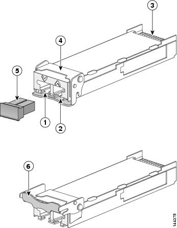
The 10-GE XFP transceiver module is a hot-swappable I/O device that plugs into 10-GE ports. (See Figure 5-14.) The XFP transceiver module connects the electrical circuitry of the system with the optical network.
Figure 5-14 10-GE XFP Transceiver Module
|
|
|
||
|
|
|
||
|
|
|
Installing the 10-GE XFP Transceiver Module
To install an XFP transceiver, follow these steps:
Step 1![]() Remove the XFP transceiver from its protective packaging.
Remove the XFP transceiver from its protective packaging.
Note![]() Do not remove the optical bore dust plugs until directed to do so later in the procedure.
Do not remove the optical bore dust plugs until directed to do so later in the procedure.
Step 2![]() Check the label on the XFP transceiver body to verify that you have the correct model for your network.
Check the label on the XFP transceiver body to verify that you have the correct model for your network.
Step 3![]() Position the XFP transceiver in front of the XFP socket opening on the module. Slide the XFP transceiver part of the way into the transceiver socket on the system module’s front panel.
Position the XFP transceiver in front of the XFP socket opening on the module. Slide the XFP transceiver part of the way into the transceiver socket on the system module’s front panel.
Step 4![]() Remove the optical bore dust plug from the XFP transceiver.
Remove the optical bore dust plug from the XFP transceiver.
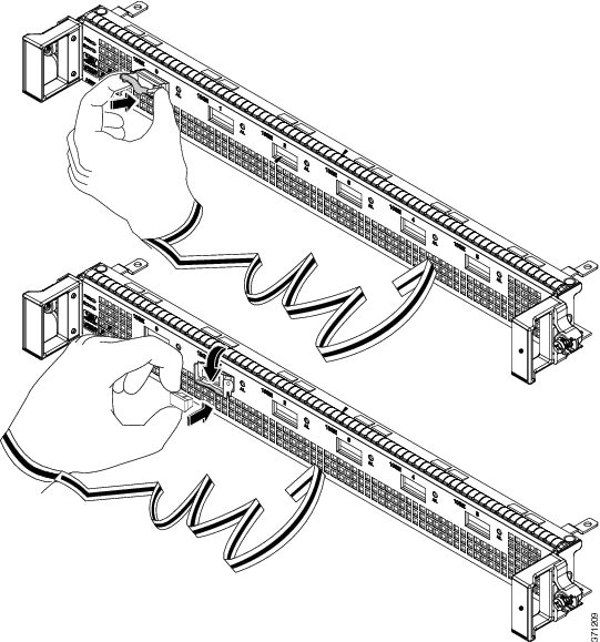
Step 5![]() Pivot the bale clasp up such that it is parallel with the transceiver body. (See Figure 5-15.)
Pivot the bale clasp up such that it is parallel with the transceiver body. (See Figure 5-15.)
Step 6![]() Continue sliding the XFP transceiver into the socket until the XFP transceiver fits into the transceiver socket connector.
Continue sliding the XFP transceiver into the socket until the XFP transceiver fits into the transceiver socket connector.
Step 7![]() Latch the XFP transceiver in the transceiver socket by pivoting the bale clasp down such that the bale clasp is perpendicular to the transceiver body. (See Figure 5-15.)
Latch the XFP transceiver in the transceiver socket by pivoting the bale clasp down such that the bale clasp is perpendicular to the transceiver body. (See Figure 5-15.)
Step 8![]() Immediately reinstall the dust plug in the XFP transceiver optical bores. Do not remove the dust plug until you are ready to attach the network interface cable.
Immediately reinstall the dust plug in the XFP transceiver optical bores. Do not remove the dust plug until you are ready to attach the network interface cable.
Figure 5-15 Installing the 10-GE XFP Transceiver Module
Note![]() 10-GE XFP transceivers are keyed to prevent incorrect insertion.
10-GE XFP transceivers are keyed to prevent incorrect insertion.
Before removing the dust plugs and making any optical connections, follow these guidelines:
- Always keep the protective dust plugs on the unplugged fiber-optic cable connectors and the transceiver optical bores until you are ready to make a connection.
- Always inspect and clean the LC connector end faces just before making any connections. Refer to the For complete information on inspecting and cleaning fiber-optic connections, refer to this white paper: http://www.cisco.com/en/US/tech/tk482/tk607/technologies_white_paper09186a0080254eba.shtml on this page for a pointer about fiber-optic inspection and cleaning.
- Always grasp the LC connector housing to plug or unplug a fiber-optic cable.
a.![]() Remove the dust plugs from the optical network interface cable LC connectors. Save the dust plugs for future use.
Remove the dust plugs from the optical network interface cable LC connectors. Save the dust plugs for future use.
b.![]() Inspect and clean the LC connector’s fiber-optic end faces.
Inspect and clean the LC connector’s fiber-optic end faces.

Tip For complete information on inspecting and cleaning fiber-optic connections, refer to this white paper:
http://www.cisco.com/en/US/tech/tk482/tk607/technologies_white_paper09186a0080254eba.shtml
c.![]() Remove the dust plugs from the XFP transceiver module optical bores.
Remove the dust plugs from the XFP transceiver module optical bores.
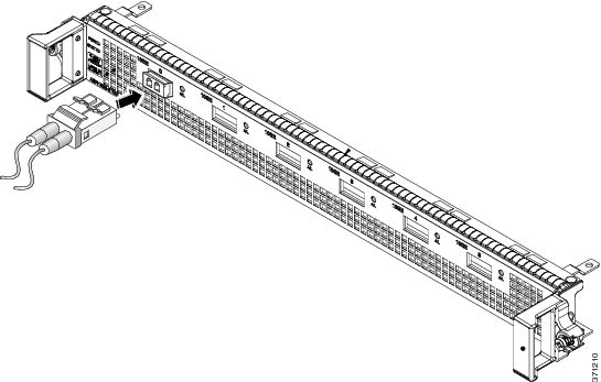
d.![]() Immediately attach the network interface cable LC connectors to the XFP transceiver module. (See Figure 5-16 for cabling the XFP transceiver module.)
Immediately attach the network interface cable LC connectors to the XFP transceiver module. (See Figure 5-16 for cabling the XFP transceiver module.)
Figure 5-16 Cabling a10-GE XFP Transceiver Module
Removing the 10-GE XFP Transceiver Module
To remove an XFP transceiver, follow these steps:
Step 1![]() Disconnect the network interface cable from the XFP transceiver connectors. Immediately reinstall the dust plug into the fiber-optic cable LC connector.
Disconnect the network interface cable from the XFP transceiver connectors. Immediately reinstall the dust plug into the fiber-optic cable LC connector.
Step 2![]() Pivot the XFP transceiver bale clasp up to release the XFP transceiver from the socket. (See Figure 4-17.)
Pivot the XFP transceiver bale clasp up to release the XFP transceiver from the socket. (See Figure 4-17.)
Step 3![]() Slide the XFP transceiver out of the socket. Pivot the bale clasp down and immediately install the dust plug into the XFP transceiver optical bores. (See Figure 4-17.)
Slide the XFP transceiver out of the socket. Pivot the bale clasp down and immediately install the dust plug into the XFP transceiver optical bores. (See Figure 4-17.)
Step 4![]() Immediately place the XFP transceiver in an antistatic bag.
Immediately place the XFP transceiver in an antistatic bag.
Figure 4-17 Removing the 10-GE XFP Transceiver
 Feedback