Supported Hardware
Components
This chapter contains information about the supported hardware components on the Cisco ASR 1001-HX Router and Cisco ASR 1002-HX Router, and contains the following sections:
- Supported EPAs
- Supported NIMs
- Supported Transceivers
- Supported Crypto Module
- Supported DIMM Upgrade
- Power Supplies
Supported EPAs
The following table lists the supported EPAs on the Cisco ASR 1002-HX Router.
PID |
Description |
|---|---|
EPA-18X1GE |
Eighteen 1GE-ports that support small form-factor pluggable (SFP) optical transceivers to provide network connectivity. Ports are numbered 0 – 17. See Table 1 for supported transceivers. |
EPA-10X10GE |
Ten 10GE-ports that support small form-factor pluggable (SFP+) optical transceivers to provide network connectivity. Ports are numbered 0 – 9. See Table 2 for supported transceivers. |
EPA-1X100GE |
EPA-1X100GE uses a CPAK module to provide network connectivity. See Table 3 for supported CPAKs. |
|
EPA-CPAK-2X40GE |
EPA-CPAK-2X40GE uses a CPAK module and a 2x40 GE breakout cable to provide network connectivity See Table 3 for supported CPAKs. |
|
EPA-1X40GE and EPA-2X40GE |
QSFP-40G-BD-RX QSFP-40G-ER4 QSFP-40G-LR4-S QSFP-40G-CSR4 QSFP-40G-SR4 QSFP-40G-SR4-S QSFP-40G-SR-BD QSFP-40G-LR4 QSFP-H40G-AOC1M QSFP-H40G-AOC2M QSFP-H40G-AOC3M QSFP-H40G-AOC5M QSFP-H40G-AOC7M QSFP-H40G-AOC10M QSFP-H40G-AOC15M QSFP-H40G-AOC20M QSFP-H40G-ACU7M QSFP-H40G-ACU10M |
An EPA has two types of LEDs: an A/L (Active/Link) LED for each port on the EPA, and a STATUS LED, as shown in the following figure.
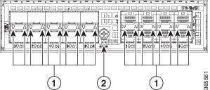
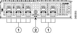
1 |
A/L |
2 |
STATUS |
Function |
Color or State |
Description |
|---|---|---|
A/L (Active/Link) |
Green |
Port is enabled and the link is up. |
Amber |
Port is enabled and the link is down. |
|
Off |
Port is not enabled. |
|
Status |
Green |
EPA is ready and operational. |
Amber |
EPA power is on and good, and the EPA is being configured. |
|
Off |
EPA power is off. |
Supported NIMs
The following table lists the supported NIMs on the Cisco ASR 1002-HX router.
|
PID |
Description |
|---|---|
|
NIM-SSD |
The solid state drive (SSD) carrier card network interface module (NIM) enables SSD support on the platform NIM slot. It provides flash storage to the platform and supports dual 2.5" (7mm max) SATA SSDs. The carrier card fits into the NIM slot in the router. The router supports only a single SSD Carrier Card NIM. |
Supported Transceivers
The Cisco ASR 1001-HX Router and Cisco ASR 1002-HX Router support the following small form-factor pluggable (SFP) and CPAK optical transceiver types:
|
Bay |
Ports |
Cisco ASR 1001-HX Router |
Cisco ASR 1002-HX Router |
|---|---|---|---|
|
Bay 0 |
Ports GE0 – GE7 |
SFP |
SFP |
|
Bay 1 |
Ports TE4 - TE7 use 1GE SFP Ports TE0 - TE3 use 10GE SFP+ |
SFP or SFP+ |
SFP+ |
|
Bay 2 |
EPA-18X1GE — Ports 0 – 17 EPA-10X10GE — Ports 0 – 9 EPA-1X100GE — Port 0 EPA-CPAK-2X40GE — Port 0 - 1 |
— |
SFP SFP+ CPAK CPAK |
|
Bay 3 |
NIM -SSD |
— |
Supported from Cisco IOS XE Fuji 16.7.1. |
|
PID |
Description |
|---|---|
|
GLC-GE-100FX |
100BASE-FX SFP transceiver module, MMF, 1310nm |
|
GLC-SX-MMD |
1000BASE-SX SFP transceiver module, MMF, 850nm, DOM |
|
GLC-LH-SMD |
1000BASE-LX/LH SFP transceiver module, MMF/SMF, 1310nm, DOM |
|
SFP-GE-T |
1000BASE-T SFP (NEBS 3 ESD) |
|
GLC-BX-U |
1000BASE-BX SFP, 1310nm |
|
GLC-BX-D |
1000BASE-BX SFP, 1490nm |
|
GLC-TE |
1000BASE-T SFP transceiver module for category 5 copper wire |
|
GLC-SX-MM |
GE SFP, LC connector SX transceiver |
|
GLC-LH-SM |
GE SFP, LC connector LX/LH transceiver |
|
GLC-EX-SMD |
GE SFP, LC Connector, EX transceiver |
|
GLC-ZX-SMD |
1000BASE-ZX SFP transceiver module, SMF, 1550nm, DOM |
|
DWDM-SFP |
1000BASE DWDM |
|
CWDM-SFP |
1000BASE CWDM |
|
PID |
Description |
|---|---|
|
SFP-10G-SR |
10GBASE-SR SFP+ Module for MMF |
|
SFP-10G-SR-X |
10GBASE-SR SFP+ Module for Extended Temp range |
|
SFP-10G-LR |
10GBASE-LR SFP+ Module for SMF |
|
SFP-10G-LR-X |
10GBASE-LR SFP+ Module for Extended Temp range |
|
SFP-10G-ER |
10GBASE-ER SFP+ Module for SMF |
|
SFP-H10GB-ACU7M |
10GBASE-CU SFP+ Cable 7 Meter, active |
|
SFP-H10GB-ACU10M |
10GBASE-CU SFP+ Cable 10 Meter, active |
|
DWDM-SFP10G-C |
10GBASE DWDM SFP+ Tunable Optic |
The following table lists the supported CPAK transceivers that can be used in the EPA-1x100GE Ethernet port adapter.
|
PID |
Description |
|---|---|
|
CPAK-100G-SR10 |
CPAK 100GBASE-SR10 Delivers 100-Gbps links over 24-fiber ribbon cables terminated with MPO/MTP connectors. It supports link lengths of 100m and 150m on laser-optimized OM3 and OM4 multifiber cables. OTN rates are also supported. |
|
CPAK-100G-LR4 |
CPAK 100GBASE-LR4 Supports 100-Gbps optical links over standard single-mode fiber (SMF, G.652) terminated with SC connectors. Nominal power consumption is less than 5.5W. The LR4 module is IEEE 802.3ba-compliant and supports link lengths of up to 10 km over standard SMF, G.652. It delivers an aggregate data signal of 100-Gbps, carried over four wavelength-division multiplexing (WDM) wavelengths operating at a nominal 25 Gbps per lane in LAN mode. OTU4 rate is also supported. Optical multiplexing and demultiplexing of the four wavelengths are managed within the module. |
|
CPAK-100G-SR4 |
CPAK 100G-SR4 Delivers 100-Gbps links for multi mode fiber, short wavelength over 4 lanes, in the 850-nm wavelength window, MPO-12 connector with up to 70m on OM3 / 100m on OM4 reach per IEEE 802.3ba requirements . |
Supported Crypto Module
The Cisco ASR 1001-HX Router and Cisco ASR 1002-HX Router support the following crypto module:
|
PID |
Description |
|---|---|
|
ASR1001HX-IPSECHW |
Cisco ASR1001-HX crypto module with no default crypto throughput. You can upgrade the throughput (8 Gbps or 16 Gbps) by applying a software-activated performance upgrade license. |
|
ASR1002HX-IPSECHW |
Cisco ASR1002-HX crypto module with no default crypto throughput. You can upgrade the throughput (8 Gbps, 16 Gbps, or 25 Gbps) by applying a software-activated performance upgrade license. |
Supported DIMM Upgrade
The Cisco ASR 1001-HX Router and Cisco ASR 1002-HX Router support the following DIMM upgrade:
|
PID |
Description |
|---|---|
|
M-ASR1001HX-16GB |
The Cisco ASR 1001-HX Router has two DIMM slots and supports 8-GB configuration by default (two 4-GB DIMMS), and can be upgraded to 16-GB (two 8-GB DIMMS) configuration. |
|
M-ASR1002HX-32GB |
The Cisco ASR 1002-HX Router has four DIMM slots and supports 16-GB configuration by default (two 8-GB DIMMS), and can be upgraded to 32-GB (four 8-GB DIMMS) configuration. |
Power Supplies
The Cisco ASR 1001-HX Router and Cisco ASR 1002-HX Router support AC or DC power supply options. The modular chassis configurations support the installation of two power supplies for redundancy. When an external power supply fails or is removed, the other power supply provides power requirements for the chassis. This allows you to hot-swap the power supply without impacting the functionality of the router.
 Caution | A router can support two AC or two DC power supplies. Do not install mixed AC and DC power supply units in the same chassis. |
Caution | The power supplies used in Cisco ASR 1001-HX Router and Cisco ASR 1002-HX Router are different and they should not be mixed or swapped. The size and structural dimensions are the same, therefore they both look alike. It would be hazardous if you accidently inserted the wrong power supply into the PEM slot. |
The power supplies are used in a 1 + 1 redundant configuration. There is no input switch on the faceplate of the power supplies. A power supply is switched from Standby to On by way of a system chassis power switch.
The following table lists the power supplies that you can order:
|
Part Number |
Power Supply |
|---|---|
|
ASR1000X-AC-750W |
Cisco ASR 1002-HX Router power supply module with plug-side intake airflow, A/C, 750W, 85–264V |
|
ASR1000X-AC-750W= |
Cisco ASR 1002-HX Router power supply module with plug-side intake airflow, A/C, 750W, 85–264V, spare |
|
ASR1000X-DC-950W |
Cisco ASR 1002-HX Router power supply module with plug-side intake airflow, DC 950W |
|
ASR1000X-DC-950W= |
Cisco ASR 1002-HX Router power supply module with plug-side intake airflow, DC 950W, spare |
|
ASR1KX-AC-750W-R |
Cisco ASR 1001-HX Router power supply module with plug-side exhaust airflow, A/C, 750W, 85–264V |
|
ASR1KX-AC-750W-R= |
Cisco ASR 1001-HX Router power supply module with plug-side exhaust airflow, A/C, 750W, 85–264V, spare |
|
ASR1KX-DC-950W-R |
Cisco ASR 1001-HX Router power supply module with plug-side exhaust airflow, DC 950W |
|
ASR1KX-DC-950W-R= |
Cisco ASR 1001-HX Router power supply module with plug-side exhaust airflow, DC 950W, spare |
Caution | The chassis has a front-to-rear airflow. All of the power supplies and fan modules in the chassis must use the same airflow direction or an error will occur with possible overheating and shut down of the router. If you power up the router with more than one airflow direction, you must power down the router and replace the modules with the wrong airflow direction before powering up the router. |
AC Power Supply
Caution | The power supplies used in Cisco ASR 1001-HX Router and Cisco ASR 1002-HX Router are different and they should not be mixed or swapped. The size and structural dimensions are the same, therefore they both look alike. It would be hazardous if you accidently inserted the wrong power supply into the PEM slot. |
 Note | The direction of the airflow is different for the Cisco ASR 1001-HX Router and the Cisco ASR 1002-HX Router as shown by the arrows in the illustrations below. |
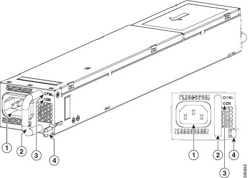
The following figure shows the Cisco ASR 1001-HX Router AC power supply.
|
1 |
AC power connector |
3 |
FAIL and OK LEDs |
|
2 |
Handle |
Retaining latch |
The following figure shows the Cisco ASR 1002-HX Router AC power supply.

|
1 |
AC power connector |
3 |
FAIL and OK LEDs |
|
2 |
Handle |
Retaining latch |
DC Power Supply
The ASR1000X-DC-950W input connector is a two-wire connector with connection polarity from left to right (when facing the unit) of positive (+) negative (–).
The power supply has a handle to be used for insertion and extraction. The module must be supported with one hand because of its length.
Caution | The power supplies used in Cisco ASR 1001-HX Router and Cisco ASR 1002-HX Router are different and they should not be mixed or swapped. The size and structural dimensions are the same, therefore they both look alike. It would be hazardous if you accidently inserted the wrong power supply into the PEM slot. |
Note | The direction of the airflow is different for the Cisco ASR 1001-HX Router and the Cisco ASR 1002-HX Router as shown by the arrows in the illustrations below. |
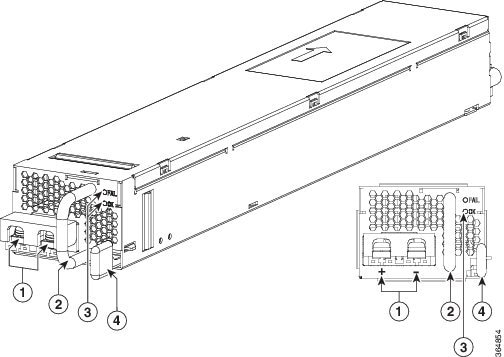
The following figure shows the Cisco ASR 1001-HX Router DC power supply.

|
1 |
DC power connections |
3 |
FAIL and OK LEDs |
|
2 |
Handle |
Retaining latch |
The following figure shows the Cisco ASR 1002-HX Router DC power supply.
|
1 |
DC power connections |
3 |
FAIL and OK LEDs |
|
2 |
Handle |
Retaining latch |
Power Supply LEDs
The following table describes the power supply LEDs.
|
Power Supply Condition |
Green (OK) LED Status |
Amber (FAIL) LED Status |
|---|---|---|
|
No AC power to all power supplies |
OFF |
OFF |
|
Power Supply Failure (includes over voltage, over current, over temperature and fan failure) |
OFF |
ON |
|
Power Supply Warning events where the power supply continues to operate (high temperature, high power and slow fan) |
OFF |
1Hz Blinking |
|
AC Present/3.3VSB on (PSU OFF) |
1Hz Blinking |
OFF |
|
Power Supply ON and OK |
ON |
OFF |
Power Supply Fans
The fans in the power supply module are used for cooling the power supply module itself while system-level cooling is provided by fans within the chassis. The power supplies do not depend on the system-level fans for cooling. Fan failure is determined by fan-rotation sensors.
Note | The fans in the Cisco ASR 1001-HX Router power supplies have plug-side exhaust airflow. The fans in the Cisco ASR 1002-HX Router power supplies have plug-side intake airflow. |
Caution | The chassis has a front-to-rear airflow. All of the power supplies and fan modules in the same chassis must use the same airflow direction or an error will occur with possible overheating and shut down of the router. If you power up the router with more than one airflow direction, you must power down the router and replace the modules with the wrong airflow direction before powering up the router. |
Note | The fans in the power supply modules will run as soon as the power supply is plugged in, even if the power switch is in the Standby position. |
Power Cords
The following table lists the supported power cords.
|
Power Cord Item Number |
Description |
|---|---|
|
CAB-AC |
Power Cord, 110 V |
|
CAB-ACA Plug |
Power Cord, Australia, 10 A |
|
CAB-ACC |
Power Cord, China |
|
CAB-ACE AC |
Power Cord, Europe, C13, CEE 7, 1.5 M |
|
CAB-ACI AC |
Power Cord, Italy, C13, CEI 23-16, 2.5 m |
|
CAB-ACR AC |
Power Cord, Argentina, C13, EL 219 (IRAM 2073), 2.5m |
|
CAB-ACS AC |
Power Cord, Switzerland, C13, IEC 60884-1, 2.5 m |
|
CAB-ACU AC |
Power Cord, UK, C13, BS 1363, 2.5 m |
|
CAB-IND AC |
Power Cord, India |
|
CAB-JPN AC |
Power Cord, Japan, C13, JIS C 8303, 2.5 m |
|
CAB-L620P-C13-US |
Power Cord, 250 VAC, 15A, NEMA L6-20 to C13, U.S. |
|
CAB-L620P-C13-JPN |
Power Cord, 250 VAC, 15A, NEMA L6-20 to C13, Japan |
|
CAB-C13-CBN Cabinet Jumper |
Power Cord, 250 VAC 10 A, C14-C13 Connectors |
|
CAB-C13-C14-JMPR Cabinet Jumper |
Power Cord, 250 VAC 13 A, C14-C15 Connector |
|
CAB-C13-C14-2M |
Power Cord Jumper, C13-C14 Connectors, 2-Meter Length |
|
CAB-C13-C14-AC |
Power Cord Jumper, C13-C14 Connectors, 3-Meter Length |
 Feedback