Console and Auxiliary Port Cables and Pinouts
Your Cisco VG450 Voice Gateway comes with the cable and adapters you need to connect a PC, an ASCII terminal, or a modem to your Cisco VG450 Voice Gateway. The cable kit includes:
-
RJ-45-to-RJ-45 rollover cable
-
RJ-45-to-DB-9 adapter cable for console connection
-
RJ-45-to-DB-25 adapter cable for modem connection
The following illustrations and tables provide cable pinout information:
- Console port to a PC—See Table A - 1 and Table A - 4.
- Console port to an ASCII terminal—See Table A - 2 and Table A - 4.
- Auxiliary port to a modem—See Table A - 3 and Table A - 4.
The console port is configured as data communications equipment (DCE); the auxiliary port is configured as data terminal equipment (DTE). Both are asynchronous serial ports and use RJ-45 connectors.
Console Port to PC
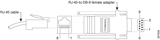
Figure A-1 shows the RJ-45-to-RJ-45 rollover cable assembly and the RJ-45-to-DB-9 female DTE adapter (labeled TERMINAL); Table A-1 lists the pinouts.
|
Console Port (DCE, RJ-45) |
RJ-45-to-RJ-45 Rollover Cable |
RJ-45-to-DB-9 Adapter “TERMINAL” |
PC Port (DTE, DB-9) |
||
|---|---|---|---|---|---|
|
Signal |
RJ-45 Pin |
RJ-45 Pin |
RJ-45 Pin |
DB-9 Pin |
Signal |
|
RTS |
11 |
8 |
8 |
8 |
CTS |
|
DTR |
2 |
7 |
7 |
6 |
DSR |
|
TxD |
3 |
6 |
6 |
2 |
RxD |
|
GND |
4 |
5 |
5 |
5 |
GND |
|
GND |
5 |
4 |
4 |
5 |
GND |
|
RxD |
6 |
3 |
3 |
3 |
TxD |
|
DSR |
7 |
2 |
2 |
4 |
DTR |
|
CTS |
81 |
1 |
1 |
7 |
RTS |
Console Port to ASCII Terminal
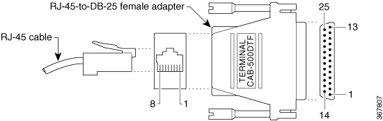
Figure A-2 shows the RJ-45-to-RJ-45 rollover cable assembly and the RJ-45-to-DB-25 female DTE adapter (labeled TERMINAL); Table A-2 lists the pinouts.
|
Console Port (DCE, RJ-45) |
RJ-45-to-RJ-45 Rollover Cable |
RJ-45-to-DB-25 Adapter “TERMINAL” |
Terminal Port (DTE, DB-25) |
||
|---|---|---|---|---|---|
|
Signal |
RJ-45 Pin |
RJ-45 Pin |
RJ-45 Pin |
DB-25 Pin |
Signal |
|
RTS |
12 |
8 |
8 |
5 |
CTS |
|
DTR |
2 |
7 |
7 |
6 |
DSR |
|
TxD |
3 |
6 |
6 |
3 |
RxD |
|
GND |
4 |
5 |
5 |
7 |
GND |
|
GND |
5 |
4 |
4 |
7 |
GND |
|
RxD |
6 |
3 |
3 |
2 |
TxD |
|
DSR |
7 |
2 |
2 |
20 |
DTR |
|
CTS |
81 |
1 |
1 |
4 |
RTS |
Auxiliary Port to Modem
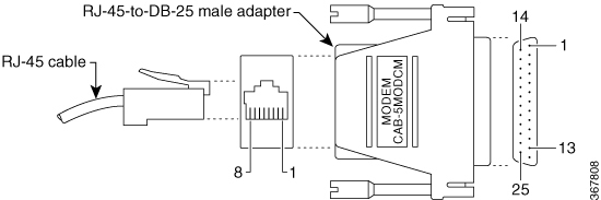
Figure A-3 shows the RJ-45-to-RJ-45 rollover cable assembly and the RJ-45-to-DB-25 male DCE adapter (labeled MODEM); Table A-3 lists the pinouts.
|
Auxiliary Port (DTE, RJ-45) |
RJ-45-to-RJ-45 Rollover Cable |
RJ-45-to-DB-25 Adapter “MODEM” |
Modem Port (DCE, DB-25) |
||
|---|---|---|---|---|---|
|
Signal |
RJ-45 Pin |
RJ-45 Pin |
RJ-45 Pin |
DB-25 Pin |
Signal |
|
RTS |
1 |
8 |
8 |
4 |
RTS |
|
DTR |
2 |
7 |
7 |
20 |
DTR |
|
TxD |
3 |
6 |
6 |
2 |
TxD |
|
GND |
4 |
5 |
5 |
7 |
GND |
|
GND |
5 |
4 |
4 |
7 |
GND |
|
RxD |
6 |
3 |
3 |
3 |
RxD |
|
DSR |
7 |
2 |
2 |
8 |
DCD |
|
CTS |
8 |
1 |
1 |
5 |
CTS |
Alternative Connections to Terminal and Modem
Your Cisco VG450 Voice Gateway ships with an RJ-45-to-RJ-45 rollover cable and two adapters for connection to a PC, a terminal, or a modem. If you want to use an RJ-45 straight-through cable or other adapters, see Table A-4 for usable cable and adapter combinations.
|
Cisco VG450 Port Connection |
RJ-45 Cable Type |
Adapter |
|---|---|---|
|
Console port to PC |
Straight-through |
DCE, DB-9 female |
|
Auxiliary port to modem |
Rollover3 |
DCE4, DB-25, male |
|
Straight-through |
DTE2, DB-25, male |

 Feedback