Installing the Router
This chapter describes the equipment and the procedures for successfully installing the IR807 and contains the following sections:
Before installing the IR807, make sure you have read and understood all of the information included in the documentation included with the product. An on-line version is also available here:
http://www.cisco.com/c/dam/en/us/td/docs/routers/access/800/807/GettingStarted/78-101247.pdf
CAUTION : Do not install the router or power supplies next to a heat source of any kind, including heating vents.
WARNING: Read the installation instructions before connecting the system to the power source. Statement 1004
WARNING: Only trained and qualified personnel should be allowed to install, replace, or service this equipment. Statement 1030
WARNING: No user-serviceable parts inside. Do not open. Statement 1073
WARNING: Ultimate disposal of this product should be handled according to all national laws and regulations. Statement 1040
WARNING: Do not locate the antenna near overhead power lines or other electric light or power circuits, or where it can come into contact with such circuits. When installing the antenna, take extreme care not to come into contact with such circuits, because they may cause serious injury or death. For proper installation and grounding of the antenna, please refer to national and local codes (for example, U.S.:NFPA 70, National Electrical Code, Article 810, Canada: Canadian Electrical Code, Section 54). Statement 1052
WARNING: This product is not intended to be directly connected to the Cable Distribution System. Additional regulatory compliance and legal requirements may apply for direct connection to the Cable Distribution System. This product may connect to the Cable Distribution System ONLY through a device that is approved for direct connection. Statement 1078
Equipment, Tools, and Connections
This section describes the equipment, tools, and connections necessary for installing your device. It contains the following topics:
Items Shipped with your Router
Unpack the box and verify that all items listed on the invoice were shipped with the Cisco 807 ISR.
The following items are shipped with your router:
- IR807 Printed Document Of Compliance
- Grounding Lug Kit
- Power Connector
Additional Items
The following items are not shipped with the router but are required for installation:
- Screws for mounting the router on a wall.
- Wire crimper for chassis grounding.
- Wire for connecting the chassis to an earth ground.
- Ethernet cables for connecting devices to the Ethernet ports.
- Ratcheting torque flathead screwdriver that exerts up to 15 in-lb (1.69 N-m) of pressure.
- A number-2 Phillips screwdriver.
Ethernet Devices
Identify the Ethernet devices that you will connect to the router: hub, servers, and workstations or PCs. Ensure that each device has a network interface card (NIC) for connecting to Ethernet ports.
Installing the Router
This section describes how to install the Cisco 807 ISR. This router can be installed on a table top or other flat horizontal surface, mounted on a wall, or DIN rail.
The recommended clearance when horizontally mounted is 1 inch on non-connector sides and 2 inches on bottom. Stacking heat-dissipating objects on top of the router is not allowed. I/O side clearance is needed as it is required to access the cable connections.
Clearance is required to attach, mount the DIN rail bracket, and Wall mount bracket. The same clearances apply when mounted vertically.
This section also describes how to attach external antennas to the routers and contains the following topics:
Warnings
WARNING: For NEC-compliant grounding, use size 14 AWG (1.6mm) or larger copper wire and a ring terminal with an inner diameter of 1/4 in. (5 to 7 mm).
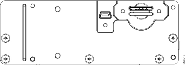
Accessing the SIM Slots
Two USIM sockets are provided with easy access via a secured panel on the back side of the router. The SIM Slots will be connected directly to the 4G radio.
Note : The IR800 series of routers use the Mini-SIM (2FF). Specifications are:
- ISO/IEC 7810:2003, ID-000
- Length - 25mm, Width - 15mm, Thickness - 0.76mm
This section describes how to install and/or replace a SIM card. Ensure that the router is not mounted to a wall, floor, or DIN rail.
CAUTION : Do not touch any part of the exposed PCB circuit area when the SIM cover is removed.
WARNING: The covers are an integral part of the safety design of the product. Do not operate the unit without the covers installed. Statement 1077
WARNING: Hot surface. Statement 1079
To access the SIM card in the Cisco IR807, follow these steps:
- Power off the router and disconnect the power cable from the power source.
- Place the router on its bottom and ensure that any installed antennas are carefully oriented or disconnected to be out of the way.
- Remove the protective cover (1 ) over the SIM slots by unscrewing the screws and setting them aside.
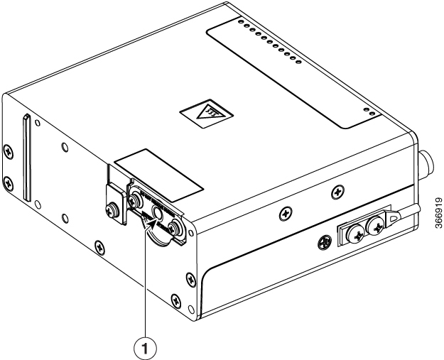
- Locate the SIM card you wish to install/replace. SIM0 is the bottom and SIM1 is the top. The following figure shows the slots with the protective cover removed.
Note : The IR807G-LTE-GA-K9 and IR807G-LTE-NA-K9 will have 2 SIM slots. The IR807G-LTE-VZ-K9 has only 1 slot.
- If SIM card is present, then push the SIM card to eject it out of the slot. Install the new SIM card by pushing it into the slot until you hear a clicking sound.
- Replace the protective cover and the screws.
Modems
The Cisco IR807 uses the WP7502, WP7504, and WP7601 series modems:
|
Product |
Carrier/Region |
Modem Used |
4G/LTE Bands Supported |
3G UMTS Bands Supported |
2G GSM/CDMA Bands supported |
|---|---|---|---|---|---|
|
IR807-LTE-GA-K9 |
EMEA |
WP7502 |
1, 3, 7, 8, 20 |
1, 8 |
E-GSM 900DCS 1800 |
|
IR807-LTE-NA-K9 |
North America/AT&T |
WP7504 |
2, 4, 5, 12, 17, 25, 26 |
2, 4, 5 |
CDMA BC0,BC1BC1- |
|
IR807-LTE-VZ-K9 |
Verizon, USA |
WP7601 |
4, 13 |
N/A |
N/A |
Installing Antennas
There are two TNC connectors on the device. The TNC connectors are used to connect to the 4G modem. The SMA connector is for the GPS antenna.
Orient the antennas. For optimum wireless performance, the antennas should be perpendicular with respect to the floor.
If the router is being mounted on a desk, orient the antennas straight up.
To attach the radio antennas to your wireless router, follow these steps:
- Manually screw the antenna tight to the TNC connectors on the front of the router.
- Orient the antennas. For optimum wireless performance, antennas should be generally perpendicular to each other.
Dual Antennas
In all cases, an antenna must be connected to the main port. It is highly recommended in order to achieve optimal performance that a second antenna is connected to the diversity port:
- Sierra Wireless WP7xxx modem series supports SIMO on LTE. WCDMA UMTS HSPA DC-HSPA+ is diversity only, without SIMO.
- The IR807 must be installed with 2 antennas (Main & Aux) to guarantee the best performance level. Using a single antenna may impact downlink performance by a minimum of 3dB, and can be much more (10-20dB) due to multipath fading (destructive interference between direct and reflected radio waves).
- In case of 3G UMTS, a solo antenna would not be able to switch to the diversity port.
Mounting on a Wall, Table, or Other Flat Surface
The Cisco IR807 can be mounted in a vertical or horizontal orientation. It can be mounted to a wall or other flat surface, and can also be mounted to a DIN rail.
TIP : When choosing a location for wall-mounting the router, consider cable limitations and wall structure.
WARNING: Read the wall-mounting instructions carefully before beginning installation. Failure to use the correct hardware or to follow the correct procedures could result in a hazardous situation to people and damage to the system. Statement 378
To mount the router on a wall or other flat surface, follow these steps:
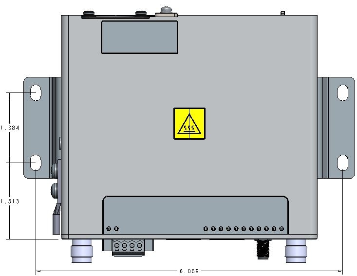
- Mark the location for the mounting brackets to attach to the wall. The dimensions are described in Figure 1.
NOTE : For hollow-wall mounting, each bracket requires two wall anchors with washers. Wall anchors and washers must be size number 10.
- Attach the mounting brackets to the bottom of the router.
- Align the mounting brackets over the mounting holes so that the larger holes on the brackets extend out over the router.
- Attach the brackets to the router with the 4 screws provided using a Phillips head driver. Torque to 13-15 in-lbs.
- Mount the router with the attached brackets to the wall using screws that are adequate for your mounting area.
- Route the cables so that they do not put a strain on the connectors or mounting hardware.
Installing a DIN Rail
The DIN Rail kit is ordered separately.
The DIN Rail can be installed in two different orientations, horizontally and vertically. There are two different mounting kits; IR807-DINRAIL(=) for horizontal mounting, and IR807-VM-DINRAIL(=) for vertical mounting.
To attach the DIN rail bracket to the Cisco IR807, follow these steps.
Mounting the DIN Rail Bracket on the Router
- First, attach the DIN rail bracket to the back of the router. The DIN rail bracket mounts in two different ways, depending on the orientation you wish to use. See Figure 1 for vertical orientation, and Figure 2 for horizontal orientation.
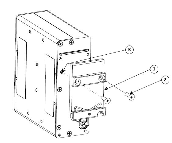
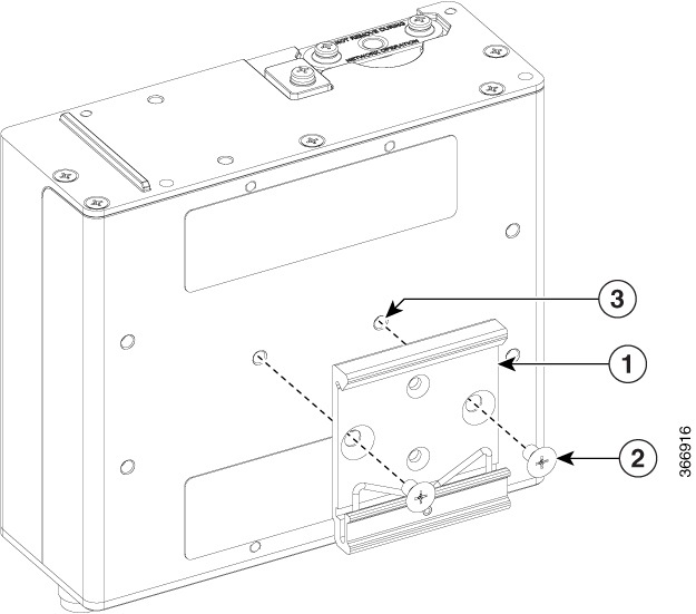
- Attach the DIN mounting bracket (1 ) to the router using the two screws provided in the kit (2 ). Position the bracket over the two mounting holes (3 ) that correspond to your orientation. Then use 13-15 in-lbs pounds of torque to screw the bracket onto the router.
- Once the bracket is attached to the router, it can be mounted onto the DIN Rail.
Attaching the Bracket onto the DIN Rail
To attach the Cisco IR807 with the bracket to a DIN rail, follow these steps. Refer to Figure 1 for details.
 Note |
The rail is 35mm wide and can be either 7.5 or 15mm high. |
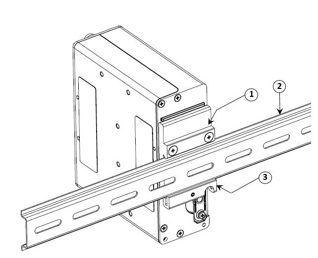
- Position the router so that the spring of the Din clip (1 ) rest on the Din rail (2 ).
- Push up the router so that the spring of the Din clip (1 ) compresses and the top hook of the Din clip (3 ) slides and clamps to the Din rail (2 ).
- To remove the router from the DIN Rail, simply reverse the procedure.
Note |
The procedure to attach the unit to the rail is the same with both orientations. |
Installing the Router Ground Connection
The router must be connected to a reliable earth ground. Install the ground wire in accordance with local electrical safety standards.
- For NEC-compliant grounding, use size 14 AWG (1.6mm) or larger copper wire and a ring terminal with an inner diameter of 1/4 in. (5 to 7 mm).
- For EN/IEC 60950-1 compliant grounding, use size 18 AWG (1.02mm) or larger copper wire.
WARNING: This equipment must be grounded. Never defeat the ground conductor or operate the equipment in the absence of a suitably installed ground conductor. Contact the appropriate electrical inspection authority or an electrician if you are uncertain that suitable grounding is available. Statement 1024
NOTE : Depending on the kit shipped with your router, the grounding lug may have one hole or two holes.
CAUTION: Cable distribution system should be grounded (earthed) in accordance with ANSI/NFPA 70, the National Electrical Code (NEC), in particular Section 820.93, Grounding of Outer Conductive Shield of a Coaxial Cable.
To install the ground connection, follow these steps:
| 1. |
Locate the ring terminal lug and screws in the packaging kit. Store the ground screws for later use. |
|
| 2. |
Use a wire stripping tool to strip the 14 or 18 AWG (1.6mm or 1.02mm) grounding wire to 0.22 in. (5.56 mm). |
|
| 3. |
Insert the ground wire into the ring terminal lug, and using a crimping tool, crimp the terminal to the wire. |
 |
| 4. |
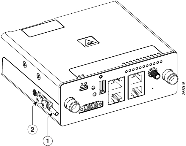
Insert the ground screws (2 ) into the grounding lug (1 ) shown in the graphic and attach the lug to the router. NOTE : if your grounding lug is a single hole type, attach it in the same manner as the dual hole using the first hole from the front panel. |
 |
| 5. |
Use a ratcheting torque screwdriver to tighten the ground screw and ring terminal to the router side panel to 3.5 in-lb (0.4 N-m). The torque should not exceed 3.5 in-lb (0.4 N-m). |
|
| 6. |
Attach the other end of the ground wire to a grounded bare metal surface, such as a ground bus, a grounded DIN rail, or a grounded bare rack. |
 Feedback