Product Overview
This chapter provides an overview of the features available for the device and contains the following sections:
Hardware Overview
This section covers the overview of the IR807.
SKU Information
Table 1 lists the different SKUs available for the Cisco 807 Integrated Services Router. All SKUs support external antenna.
|
SKU ID |
Description |
Modem Type |
|---|---|---|
|
IR807G-LTE-VZ-K9 |
North America (Verizon) |
WP7601 |
|
IR807G-LTE-NA-K9 |
North America (AT&T) |
WP7504 |
|
IR807G-LTE-GA-K9 |
EMEA |
WP7502 |
Note : The IR809G-LTE-VZ-K9 SKU has a single SIM card socket. The IR807G-LTE-NA-K9 and IR807G-LTE-GA-K9 are equipped with dual SIM card sockets. Graphics in this guide show the dual SIM SKUs.
Front Panel Icons and LEDs
The IR807 uses icons to show the different features of the device. Table 1 shows Icons and their associated LEDs with descriptions. LEDs are visible from the top cover and from the front panel. The LEDs allows easy visibility for wall and desk mounted installations regardless of chassis orientation. Table 3 shows the Icons without associated LEDs and their descriptions.
|
Icon |
Description/Activity |
Icon |
Description/Activity |
|---|---|---|---|

|
System - Power and System Status. Off — No power Green Steady on — Normal operation Green Flashing — Boot up phase or in ROM Monitor mode Amber Steady on — Power is OK but possible internal FPGA program failure |

|
Alarm - Alarm Input Status Off — Normal operation Red - Alarm State on the Alarm Input |

|
VPN Off — No VPN tunnel Steady Green — At least one VPN tunnel is up |

|
User Configurable LED |

|
GPS - GPS Status Off — GPS not configured Steady Green — GPS configured Slow Flash — GPS Acquiring in Standalone GPS Fast Flash — GPS Acquiring in Assisted GPS Slow Flash is defined as the LED will be on for 0.25 seconds and off for 0.75 seconds.Fast Flash is defined as the LED will be on for 0.25 seconds and off for 0.25 seconds. |

|
RJ45 Fast Ethernet Ports -Link Status 0:1 Off — No link Steady Green — Link is up Flashing — Transmitting and Receiving data |

|
RSSI - Received Signal Strength Indication The RSSI LEDs are a 3 LED bar graph to indicate signal strength. Their functionality is described in the RSSI LED Table 2. |

|
SIM Slots - SIM0/SIM1 Off — No USIM Green — USIM installed and active |

|
WWAN - Wireless WAN Activity Off — Offline On — In Service Flash (on 200ms off 5 sec) — No Service Flash (on 1 sec off 1 sec) — Low Power Mode Flash (on 5 sec off 200ms) — Roaming Flash (on 400ms off 100ms) — Data Active |
|
RSSI |
RSSI (2) |
RSSI (1) |
RSSI (0) |
|---|---|---|---|
|
Green |
Green |
Green/Amber |
|
|
< -110dBm |
Off |
Off |
Off |
|
-110 to -90dBm |
Off |
Off |
On - Amber |
|
-90 to -75dBm |
Off |
Off |
On - Green |
|
-75 to -60dBm |
Off |
On - Green |
On - Green |
|
> -60dBm |
On - Green |
On - Green |
On - Green |
|
Icon |
Description |
Icon |
Description |
|---|---|---|---|

|
Console |

|
USB 2.0 Type A Port for Storage and Networking |

|
Grounding point (located on side of device) |

|
Reset Button |

|
DC Power Input (12V to 48V) |

|
DC Power Return |

|
Alarm Common |

|
Alarm IN |

|
Serial Ports |

|
Fast Ethernet Ports |

|
Antenna 1 (TNC) Main |

|
Antenna 1 (TNC) Div |

|
Warning |
Figure 1shows the front panel details of the Cisco IR807.
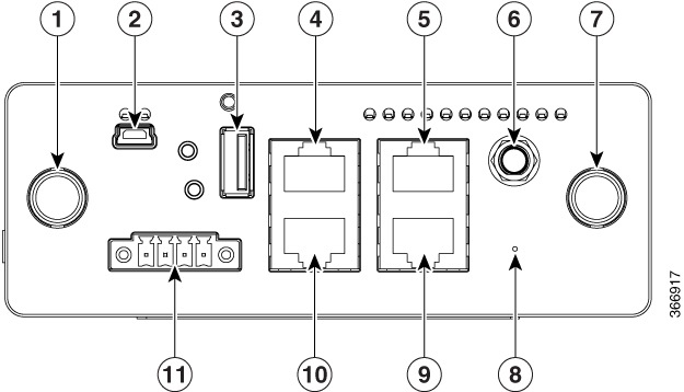
|
1 |
Antenna 1 (TNC) MAIN |
7 |
Antenna 2 (TNC) DIV |
|---|---|---|---|
|
2 |
USB Console (Type B) |
8 |
Reset Button |
|
3 |
USB Type A |
9 |
FE1 10/100 Base-T RJ-45 |
|
4 |
S0 (DTE) |
10 |
S1 (DCE) |
|
5 |
FE0 10/100 Base-T RJ-45 |
11 |
External DC Power Input and Alarm |
|
6 |
GPS (SMA) |
Figure 2 shows the back panels details of the Cisco IR807.
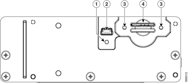
|
1 |
Screw hole for protective cover over USB |
|---|---|
|
2 |
USB Type B (under a protective cover) Reserved to be used with Modem for external provisioning. |
|
3 |
Screw holes for protective cover over SIMs (one on each side) |
|
4 |
SIM0 (bottom) and SIM1 (top) Slots |
Memory
The Cisco IR807 uses flash memory and main memory. The flash memory contains the Cisco IOS software image and the boot flash contains the ROMMON boot code. All memory components are factory default and not upgradeable by the end user.
The following table shows the memory allocation.
|
Memory |
Specification |
|---|---|
|
Default and maximum DRAM |
1GB |
|
Default and maximum flash memory |
4 GB eMMC |
Antennas
The Cisco IR807 ships without antennas. All antennas are options that can be ordered separately.
There are two TNC connectors on the front side of the device. The TNC connectors are used to connect to the 4G modem. The SMA connector is for the GPS antenna.
NOTE : Before choosing your antenna type and installation scenario, read through the following information.
Supported Cisco Antennas and Cables
The following section lists the supported Antennas and Cables for the Cisco IR807. For detailed information about Cisco Antennas, please refer to the following guides:
Cisco Industrial Routers and Industrial Wireless Access Points Antenna Guide:
Cisco Aironet Antennas and Accessories Reference Guide
The following antennas and cables are available:
ANT-3-4G2G1-O
Description: Cisco Quinta 3 element 3-in-1 transportation antenna
- 2x 4G cellular, 1xGPS
- Color: Black radome
- RoHS compliant
- Environment: Outdoor
Electrical Specifications:
- Frequency ranges: 698 to 960 MHz and 1710 to 2700 MHz
- Typical gain (dBi): 698 to 960 MHz = 2.6 dBi, and 1710 to 2700 MHz = 4.6 dBi
- Efficiency: 60%
- Polarization: Linear and vertical
- Port impedance: 50 Ohms
- Voltage standing wave ratio (VSWR): < 2.1:1 (698 to 960 MHz) and < 2.0:1 (1710 to 2700 MHz)
- Radiation pattern: Omnidirectional
- Integrated RF cables: 2 ft, LMR-195 type, TNC (male)
GPS electrical specifications:
- Frequency range: 1575.42 MHz +/–1 MHz (GPS L1)
- Amplifier gain: 27dB +/–3dB
- Noise figure: 4dB max
- Port impedance: 50 Ohms
- Output VSWR: < 2.0:1
- Radiation pattern: RHCP
- DC voltage: 2.7–12V DC
- DC current: < 20 mA over –40 to 85°C temperature range
- Integrated RF cable: 17 ft, LMR-100 type, SMA(m)
Mechanical and environmental specifications:
- Mount style: Vehicular roof or similar; stud and nut mount
- Environment: Outdoor, vehicular roof, transportation ruggedized and qualified to subset of SAE1455 and MILSTD 810G
- Connectors: 2 x TNC(m) cellular and 1 x SMA(m) GPS
- Antenna dimensions: 7.1 in. diameter x 2.4 in. height (18.0 x 6.5 cm), excluding RF cables
- Weight: 1.48 lb (0.67 kg)
- Operating temperature range: –40 to 70°C
- Storage temperature: –40 to 85°C
- Maximum power: 10W
- Radome: Polycarbonate, UV, black
- Material substance compliance: ROHS compliant
ANT-4G-OMNI-OUT-N
Description: Cisco outdoor omnidirectional antenna for 2G, 3G, and 4G LTE cellular
- UV-stable radome
- Mast-mounting bracket
- Applicable for both 2G and 3G solutions
- Domestic LTE 700 band and global LTE 2600 band
- Domestic cellular and global GSM
- WiMAX 2300 and 2500
Electrical Specifications:
- Frequency ranges: 698 to 960 MHz, 1710 to 2170 MHz, and 2300 to 2700 MHz
- Nominal gain (dBi): 698 to 960 MHz = 1.5 dBi, and 1710 to 2700 MHz = 3.5 dBi
- 3 dB beam width (E plane): 698 to 960 MHz = 81 degrees, 1710 to 2170 MHz = 75 degrees, and 2300 to 2700 MHz = 100 degrees
- 3 dB beam width (H plane): 360 degrees, omnidirectional
- Polarization: vertical and linear
- Nominal impedance: 50 Ohms
- VSWR: < 2.5:1 (698 to 960 MHz) and < 2.0:1 (1710 to 2690 MHz)
- Radiation pattern: omnidirectional
Mechanical Specifications:
- Mount style: mast mount, upright position only
- Environment: outdoor
- Connector: N-type socket
- Antenna length (height): 9.8 x 1 in. (24.9 x 2.45 cm)
- Weight: 1.5 lb. (0.68 kg)
- Dimensions (H x Outside dimensions): 9.8 x 1 in. (248 x 24.5 mm)
- Operating temperature range: -22° to 158°F (-30° to 70°C)
- Storage temperature: -40° to 185°F (-40° to 85°C)
- Maximum power: 20W
- Radome: polycarbonate, UV, white
- Material substance compliance: ROHS compliant
ANT-4G-PNL-OUT-N
Description - Cisco multiband panel outdoor 4G LTE antenna:
- Supports 3G and 4G LTE solutions
- Multiband
- Wall mount and mast mount
- Indoor and outdoor
- Dual type-N socket connector
Electrical specifications:
- Frequency ranges: 698 to 960 MHz and 1710 to 2700 MHz
- VSWR: 2.0:1 maximum
- Gain: 5.5 to 10.5 dBi (698 to 960 MHz) and 6.5 to 9.0 dBi (1710 to 2700 MHz)
- 3-dB beam width (vertical plane): 55 to 70 degrees = 698 to 960 MHz, 53 to 98 degrees = 1710 to 2200 MHz, 60 to 70 degrees = 2200 to 2500 MHz, and 55 to 70 degrees = 2500 to 2700 MHz
- 3-dB beam width (horizontal plane): 55 to 70 degrees = 698 to 960 MHz and 50 to 90 degrees = 1710 to 2200 MHz
- F/B ratio: > 15 dB, typical 20 dB = 698 to 960 MHz, and > 17 dB, typical 23 dB = 1700 to 2700 MHz
- Isolation: > 30 dB
- Polarization: slant +/- 45 degrees
- Nominal impedance: 50 Ohms
- Radiation pattern: directional
Mechanical specifications:
- Mount style: wall or mast mount
- Environment: outdoor
- Connector: dual type N female (direct connect or dual 12 in (30 cm))
- Antenna length (height): 11.6" (2.95 cm)
- Temperature Range (Operating): -22 to 158-degrees F (-30 to 70° C)
- Storage temperature: -40 to +85° C
- Wind rating: 160 km/H
- IP rating: IP54
- Radome: polycarbonate, UV resistant, white
- Material substance compliance: ROHS compliant
ANT-4G-SR-OUT-TNC
Description - Cisco integrated 4G LTE low-profile outdoor saucer antenna:
- Applicable for both 3G and 4G LTE solutions
- Domestic LTE 700 band and global LTE 2600 band
- Domestic cellular and global GSM
- Weatherproof UV stable radome
- Performance optimized
- Excellent flame rating
Electrical specifications:
- Frequency ranges: 698 to 960 MHz and 1710 to 2700 MHz
- Peak gain with 1-ft cable: 1.5 dBi (698 to 960 MHz) and 3.7 dBi (1710 to 2700 MHz)
- Peak gain with 15-ft cable: 0.8 dBi (698 to 960 MHz) and 0.2 dBi (1710 to 2700 MHz)
- Average efficiency with 1-ft cable: 90% (698 to 960 MHz) and 82% (1710 to 2700 MHz)
- Average efficiency with 15-ft cable: 60% (698 to 960 MHz) and 40% (1710 to 2700 MHz)
- Nominal impedance: 50 Ohms
- VSWR (maximum): 2.0:1 (698 to 960 MHz) and 2.0:1 (1710 to 2700 MHz)
Mechanical specifications:
- H-plane 3 dB beam width: omnidirectional
- Polarization: linear and vertical
- Power: 3W
- Cable: 15-ft LMR 195
- RF connector: type N (f); TNC (plug) available
- Mount style: ceiling mount
- Radome: PC/ABS, UV stable, black
- Material substance compliance: RoHS compliant
- Operational temperature: -22° to 158°F (-30° to 70°C)
- Storage temperature: -40° to 185°F (-40° to 85°C)
- Environment: indoor
- Dimensions (H x Outside dimensions): 3.4 x 7.9 in. (87 x 200 mm)
ANT-4G-DP-IN-TNC
Description : Cisco indoor swivel-mount dipole antenna
- Low-profile blade style sheath
- Applicable for both 3G and 4G solutions
- Domestic LTE 700 and global LTE 2600 bands
- Domestic cellular and global GSM
- Conformance to RoHS
- Complete cellular and 4G data communications in a single antenna
Electrical Specifications:
- Operating frequency ranges: 698 to 806 MHz, 824 to 894 MHz, 880 to 960 MHz, 1710 to 1880 MHz, 1850 to 1990 MHz, 1920 to 2170MHz, 2100 to 2500 MHz and 2500 to 2690 MHz
- Peak gain: 0.5 dBi (698 to 960 MHz) and 2.2 dBi (1710 to 2700 MHz)
- Average efficiency: 55% (698 to 960 MHz) 73% (1710 to 2700 MHz)
- Maximum input power: 3 watts
- Voltage standing wave ratio (VSWR): < 2.5:1
- Characteristic impedance: 50 Ohms
- Polarization: linear
Mechanical Specifications:
- Type: dipole
- Antenna dimensions (L x W x D): 229 mm x 30.5 mm x 15 mm
- Mount style: direct mount
- Environment: indoor
- RF Connector: TNC (m)
- Antenna weight: 49 g
- Temperature rating: -31 to 158 degrees F (-35 to +70 degrees C)
- Material substance compliance: RoHS compliant
4G-LTE-ANTM-O-3-X
Description :
- Multiband low profile indoor or outdoor omnidirectional antenna (IP67 ingress protection)
- Ceiling mount, dual 4G LTE and standalone GPS
Electrical Specifications:
- Frequency range: 698 to 960 MHz and 1710 to 2700 MHz
- Gain: 2.5 dBi
- Maximum power: 3W
- Connector: SMA with TNC male adapters, and SMA for GPS
- VSWR: < 2.5:1
- Nominal impedance: 50 Ohms
- Polarization: linear vertical
Mechanical Specifications:
- Radome material: white, black, red, or blue ABS, UL-94 V0
- Cable: 4 ft RG174 VW-1 compliant
- Height and base diameter: 90 mm and 137 mm
- Temperature rating: -40° to 185°F (-40° to 85°C)
- Mounting: 5/8-inch lug with serrated face nut (5/8-inch diameter hole through mounting surface)
- Can be used with the following cable extensions: 4G-CAB-ULL-20 and 4G-CAB-ULL-50
4G-LTE-ANTM-D
Description :
- Omnidirectional dipole antenna is designed for indoor use with Cisco 4G and Cisco 3G wireless Integrated Services Routers Generation 2 systems
- Articulating Joint —It can be rotated 360 degrees and is capable of maneuvering into three stop positions: 0 degrees, 45 degrees, and 90 degrees.
- Male threaded Neill-Concelman (TNC) Connector —It lets you directly mount the antenna to any Cisco 4G and Cisco 3G wireless Integrated Services Router (ISR) EHWIC with a TNC connector (Cisco 4G-LTE-ANTM-D Ominidirectional Dipole Antenna, TNC Connector, and Articulation Joint). The threads on the connector must comply with the ANSI 7/16-28 UNEF 2B thread specification.
Electrical Specifications:
-
Frequency range:
- 698–806 MHz
- 824–894 MHz
- 925–960 MHz
- 1710–1885 MHz
- 1920–1980 MHz
- 2110–2170 MHz
- 2500–2690 MHz
- Maximum input power: 3W
- Connector: TNC male
- VSWR: 2.5:1 or less
- Nominal impedance: 50 Ohms
- Maximum Peak Gain: 2 dBi
Mechanical Specifications:
- Antenna base and radome color: Cisco Raven Black
- Dimensions: 9 (L) x 1.2 (W) x 7/16 in (D) (229 x 30.5 x 11 mm)
- Temperature rating: –22° to 158°F (–30° to 70°C)
Antenna Extension 4G-AE015-R
Description :
- Single-unit antenna extension base (15 ft [457.2 cm])
Electrical Specifications:
- Frequency range: 6 GHz
- Attenuation: less than 3 dB at or below 2.5 GHz
- Base connector: TNC socket
- Pigtail connector: TNC plug
Mechanical Specifications:
- Base material: Cisco gray UL94 V0 PC/ABS plastic
- Dimensions: 2.8 x 2.4 x 1.8 in. (7.1 x 6.1 x 4.6 cm)
- Weight: 6 oz. (0.17 kg)
- Cable: 15 ft. (457.2 cm) non-plenum rated Pro-Flex Plus 195
Antenna Extension 4G-AE010-R
Description :
- Single-unit antenna extension base (10 ft. [304.8 cm], one cable included)
Electrical Specifications:
- Frequency range: 6 GHz
- Attenuation: less than 3 dB at or below 2.5 GHz
- Base connector: TNC socket
- Pigtail connector: TNC plug
Mechanical Specifications:
- Base material: UL 94 V0PC and ABS plastic
- Dimensions: 2.8 x 2.4 x 1.8 in. (7.1 x 6.1 x 4.6 cm)
- Weight: 6 oz. (0.17 kg)
- Cable: 10 ft. (304.8 cm) non-plenum rated Pro-Flex Plus 195
Modem Support
The Cisco IR807 uses the WP7502, WP7504, and WP7601 series modems. The software download page can be found here:
https://software.cisco.com/download/navigator.html?mdfid=286288566&flowid=76082
|
Region/Carrier |
Modem Used |
4G/LTE |
3G UMTS/HSPA |
2G GSM/GPRS/EDGE |
|---|---|---|---|---|
|
US / Verizon |
WP7601 |
700 MHz (band 13) 1700/2100 MHz (band 4 AWS) |
N/A |
N/A |
|
North America/ AT&T |
WP7504 |
700 MHz (band 17) 1900 MHz (band 2 PCS) 1700/2100 MHz (band 4 AWS) 1850-1915 (band 25) 814-849 (band 26) |
850 MHz (band 5) 1900 MHz (band 2) |
850 MHz 1900 MHz |
|
EMEA |
WP7502 |
800 MHz (band 20) 900 MHz (band 8) 1800 MHz (band 3) 2100 MHz (band 1) 2600 MHz (band 7) |
850 MHz 900 MHz 1900 MHz 2100 MHz |
850 MHz 900 MHz 1900 MHz 2100 MHz |
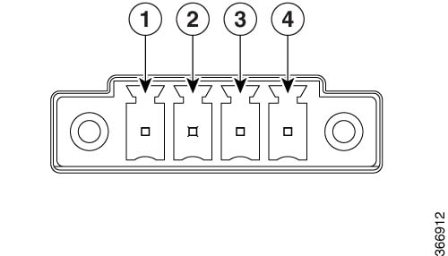
Power Supply
The Cisco IR807 comes with an external DC power connector. The 4-pin power entry connector (receptacle) is mounted to the unit. The 4-pin power entry mating connector (plug) is attached to the receptacle. It is removed during installation and used to connect to the DC power source, then reattached to provide power to the unit.
Refer to Figure 1 for the location and values of the power connector.
|
Pin Number |
Name |
Description |
Color |
|---|---|---|---|
|
1 |
DC In + |
DC Power Positive Input |
Red |
|
2 |
DC In - |
DC Power Return |
Black |
|
3 |
ALM REF |
Alarm Common |
N/A |
|
4 |
ALM IN |
Alarm Input |
N/A |
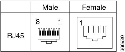
RJ45 Ports
The IR807 supports two ISOLATED RS232 ports which conforms to EIA-561 standard. RS232 pin out is shown in the following figure applies to serial 0 and serial 1, but the directions of the DTE and DCE port are opposite.
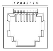
The RS232 DTE pin out applies to both serial 0 and serial 1. This port is not shared with the Console port.
Note: The RS232 DTE pin out is different from the Cisco standard Console/Auxiliary port.
The following figure shows the characteristics of the S0 and S1 ports:
The following table shows the S0 and S1 Details
|
Pin Number |
Description |
Abbreviation |
DTE |
DCE |
|---|---|---|---|---|
|
1 |
DCE Ready, Ring Indicator |
DSR/RI |
<— |
—> |
|
2 |
Received Line Signal Detector |
DCD |
<— |
—> |
|
3 |
DTE Ready |
DTR |
—> |
<— |
|
4 |
Signal Ground |
COM |
||
|
5 |
Received Data |
RxD |
<— |
—> |
|
6 |
Transmitted Data |
TxD |
—> |
<— |
|
7 |
Clear To Send |
CTS |
<— |
—> |
|
8 |
Request To Send |
RTS |
—> |
<— |
Accessories
See the following table for a partial listing of IR807 Accessories.
|
Cisco Part Number |
Accessory |
|---|---|
|
PWR-IE50W-AC |
DIN-rail mount AC/DC power supply - Input AC 100-240V/1.25A or Input DC 125-250V/1A, Output DC 24V/2.1A |
|
IR807-DINRAIL(=) |
Din rail kit and mounting screws for horizontal mounting |
|
IR807-VM-DINRAIL(=) |
Din rail kit and mounting screws for vertical mounting |
|
IR807-WALLMNT(=) |
Wall mount kit and mounting screws |
|
CAB-CONSOLE-USB 37-1090-01 |
Cisco USB Type A Male to Mini B Male 6ft Console Cable |
- Depending on your particular model of the router, there will be either a single hole or double hole grounding.
- 53-100629-01 - Contains Getting started with the Cisco 807 Integrated Services Router document, associated hardware, and the single hole grounding kit.
- 53-100797-01 - Contains Getting started with the Cisco 807 Integrated Services Router document, associated hardware, and the two hole grounding kit.
 Feedback