Installing and Upgrading Internal Modules and FRUs
Installing and Upgrading Internal Modules and FRUs
This document describes how to install and upgrade internal modules and field replaceable units (FRUs) in the Cisco 1100 Series Integrated Services Routers (ISRs). The install and upgrade information is contained in these sections:
- Safety Warnings
- Accessing Internal Modules
- Locating Internal and External Slots for Modules
- Removing and Replacing the USB Flash Token Memory Stick
- AC Power Supplies
- Installing and Removing SFP Modules
Safety Warnings
 Warning | Class 1 laser product. Statement 1008 |
Warning | Only trained and qualified personnel should be allowed to install, replace, or service this equipment. Statement 1030 |
Accessing Internal Modules
To access the internal modules on the router, you must first disconnect from the power source and then remove the chassis cover. See the Replacing the Cover section for instructions on how to remove and later replace the chassis cover on the routers.
Warning | Before opening the unit, disconnect the telephone-network cables to avoid contact with telephone-network voltages. Statement 1041 |
Replacing the Chassis Cover
The Cisco 1100 Series ISRs have a removable cover.
Do not run the router with the cover off. Doing so can cause the router to overheat very quickly.
Use a number-2 Phillips screwdriver to perform the following tasks.
Removing the Cover
To remove the cover, perform the following steps.
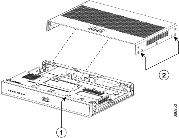
Replacing the Cover
To replace the cover, perform the following steps.
| Step 1 | Read the Safety Warnings and disconnect the power supply before you begin. |
| Step 2 | Confirm the router is turned off and disconnected from the power supply or power supplies. If a redundant power is used disconnect from the redundant power supply. |
| Step 3 | Place the chassis on a flat surface. |
| Step 4 | Locate the cover hooks on the mating slots and slide the cover towards the bezel side. |
| Step 5 | Install seven screws on each side. |
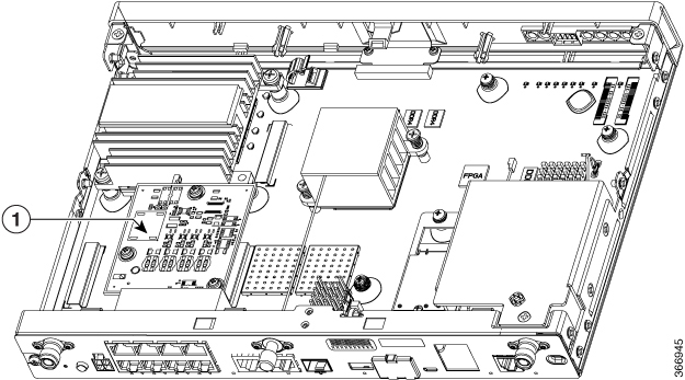
Locating Internal and External Slots for Modules
This section describes the locations of internal modules on the router motherboard. Internal modules include PoE daughter card on the Cisco1100 Series ISRs.
|
1 |
PoE Module |
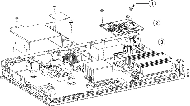
Installing the Internal PoE Daughter Card
Use the following procedure to install an Internal PoE daughter card:
| Step 1 | Read the Safety Warnings and disconnect the power supply before you perform any module installation. | ||||||||
| Step 2 | Confirm the router is turned off and disconnected from the power supply. | ||||||||
| Step 3 | Open the chassis according to the instructions in the Removing the Chassis section. | ||||||||
| Step 4 | Locate the three metal standoff holes, and install the metal standoffs into the three holes. Make sure that the standoffs are straight when installed. Tighten them gently but firmly, to a torque of 6-8 in-lbf. | ||||||||
| Step 5 | Place the PoE daughter card on top of the three metal standoffs, lining up the screw holes in the PoE daughter card with the metal standoffs. | ||||||||
| Step 6 | Gently push the PoE daughter card down towards the system board until it is firmly fixed. | ||||||||
| Step 7 | Insert the three M3 (48-0530-01) screws provided, through the PoE daughter card and into the metal standoffs. Tighten the screws using a torque of 5 in-lb. | ||||||||
| Step 8 | Close the chassis cover according to the instructions in the Replacing the Cover section, and connect the power supply cable.
|
Removing and Replacing the Internal PoE Daughter Card
Use the following procedure to remove and replace the Internal PoE daughter card:
| Step 1 | Read the Safety Warnings and disconnect the power supply before you remove or replace the module. | ||
| Step 2 | Open the chassis, locate the PoE daughter card assembly. | ||
| Step 3 | Remove the three M3 (48-0530-01) screws. | ||
| Step 4 | Pull the PoE daughter card out of the connector. If replacing the card, insert the new PoE daughter card and tighten the screws to a torque of 5 in-lb. | ||
| Step 5 | Place the removed card in an anti-static bag to protect it from ESD damage.
|
Removing and Replacing the USB Flash Token Memory Stick
The Cisco 1100 Series ISRs contain port for a 1 GB flash token memory stick to store configurations or Cisco IOS XE consolidated packages.
 Note | Only Cisco USB Flash memory modules are supported by Cisco routers. |
 Caution | Do not remove a USB Flash memory module when issuing some file access command or a read/write operation to the Flash memory module when it is processing. The router might reload or the USB Flash memory module can be damaged. You can check to see if the USB activity LED on the router front panel is flashing, prior to the removal of the USB device |
To remove and then replace a USB flash token memory stick from the router, follow these steps:
What to Do Next
This completes the USB Flash memory installation procedure.
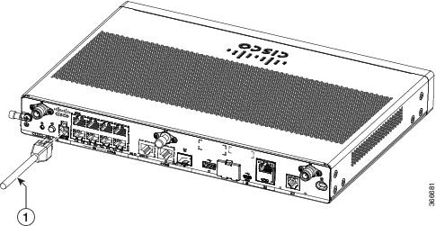
AC Power Supplies
Overview of the AC Power Supply
Power supply of the Cisco 1100 Series ISRs is an external AC to DC power adapter. The external power adapter DC power connector plugs in to the router 4-pin power connector, to power the unit.
|
1 |
Power Cable |
Installing and Removing SFP Modules
This section describes how to install optional small-form-factor pluggable (SFP) modules in the router to provide optical Gigabit Ethernet connectivity.
The SFP module installs into a slot on the router rear panel. When selected in Cisco IOS software, it is assigned port gigabitethernet 0/0/0. The default is the built-in RJ-45 1000Base-T connector, which is enabled on this port.
Only SFP modules certified by Cisco are supported on the routers.
|
Cisco Model Number |
Minimum IOS-XE Version |
Description |
|---|---|---|
| GLC-EX-SMD |
3.15 |
1000BASE-EX SFP transceiver module, SMF, 1310nm, DOM |
|
GLC-LH-SM |
3.10 |
GE SFP, LC connector LX/LH transceiver |
|
GLC-ZX-SM-X= |
1000Base-ZX |
9/125 |
| GLC-LH-SMD | 3.10 |
GE SFP, LC connector LX/LH transceiver; with DOM |
|
GLC-SX-MM |
3.10 |
GE SFP, LC connector SX transceiver |
| GLC-SX-MMD | 3.10 |
GE SFP, LC connector SX transceiver; with DOM |
| GLC-ZX-SM | 3.10 |
1000BASE-ZX SFP |
| GLC-ZX-SMD | 3.16.1 |
1000BASE-ZX SFP; with DOM |
| GLC-FE-100FX | 3.10 | 100BASE-FX SFP for FE port |
| GLC-FE-100LX | 3.10 |
100BASE-LX SFP for FE port |
| GLC-FE-100ZX | 3.10 |
100BASE-ZX SFP (80km) |
| GLC-FE-100EX | 3.10 |
100BASE-EX SFP (40km) |
| GLC-FE-100BX-D | 3.11 |
100BASE-BX10-D SFP |
| GLC-FE-100BX-U | 3.11 | 100BASE-BX10-U SFP |
| GLC-GE-100 V02 | 3.10 |
100 V02 SFP on GE ports |
| GLC-BX80-D-I | 3.16.1 |
1000BASE-BX80 SFP, 1570NM |
| GLC-BX80-U-I | 3.16.1 |
1000BASE-BX80 SFP, 1490NM |
| GLC-BX40-D-I | 3.16.1 |
1000BASE-BX40 SFP, 1550NM |
| GLC-BX40-U-I | 3.16.1 |
1000BASE-BX40 SFP, 1310NM |
| GLC-BX-D | 3.10 | 1000BASE-BX SFP, 1490NM |
| GLC-BX-U | 3.10 | 1000BASE-BX SFP, 1310NM |
| SFP-GE-S | 3.13 | 1000BASE-SX SFP transceiver module for MMF, 850-nm wavelength, extended operating temperature range and DOM support, dual LC/PC connector |
| CWDM-SFP-1470 | 3.10 | CWDM 1470 NM SFP Gigabit Ethernet and 1G/2G FC |
| CWDM-SFP-1490 | 3.10 | CWDM 1490 NM SFP Gigabit Ethernet and 1G/2G FC |
| CWDM-SFP-1510 | 3.10 | CWDM 1510 NM SFP Gigabit Ethernet and 1G/2G FC |
| CWDM-SFP-1530 | 3.10 | CWDM 1530 NM SFP Gigabit Ethernet and 1G/2G FC |
| CWDM-SFP-1550 | 3.10 | CWDM 1550 NM SFP Gigabit Ethernet and 1G/2G FC |
| CWDM-SFP-1570 | 3.10 | CWDM 1570 NM SFP Gigabit Ethernet and 1G/2G FC |
| CWDM-SFP-1590 | 3.10 | CWDM 1590 NM SFP Gigabit Ethernet and 1G/2G FC |
| CWDM-SFP-1610 | 3.10 | CWDM 1610 NM SFP Gigabit Ethernet and 1G/2G FC |
| DWDM-SFP-3033 | 3.10 | DWDM SFP 1530.33 nm SFP (100 GHz ITU grid) |
| DWDM-SFP-3112 | 3.10 | DWDM SFP 1531.12 nm SFP (100 GHz ITU grid) |
| DWDM-SFP-3190 | 3.10 | DWDM SFP 1531.90 nm SFP (100 GHz ITU grid) |
| DWDM-SFP-3268 | 3.10 | DWDM SFP 1532.68 nm SFP (100 GHz ITU grid) |
| DWDM-SFP-3425 | 3.10 | DWDM SFP 1534.25 nm SFP (100 GHz ITU grid) |
| DWDM-SFP-3504 | 3.10 | DWDM SFP 1535.04 nm SFP (100 GHz ITU grid) |
| DWDM-SFP-3582 | 3.10 | DWDM SFP 1535.82 nm SFP (100 GHz ITU grid) |
| DWDM-SFP-3661 | 3.10 | DWDM SFP 1536.61 nm SFP (100 GHz ITU grid) |
| DWDM-SFP-3819 | 3.10 | DWDM SFP 1538.19 nm SFP (100 GHz ITU grid) |
| DWDM-SFP-3898 | 3.10 | DWDM SFP 1538.98 nm SFP (100 GHz ITU grid) |
| DWDM-SFP-3977 | 3.10 | DWDM SFP 1539.77 nm SFP (100 GHz ITU grid) |
| DWDM-SFP-4056 | 3.10 | DWDM SFP 1540.56 nm SFP (100 GHz ITU grid) |
| DWDM-SFP-4214 | 3.10 | DWDM SFP 1542.14 nm SFP (100 GHz ITU grid) |
| DWDM-SFP-4294 | 3.10 | DWDM SFP 1542.94 nm SFP (100 GHz ITU grid) |
| DWDM-SFP-4373 | 3.10 | DWDM SFP 1543.73 nm SFP (100 GHz ITU grid) |
| DWDM-SFP-4453 | 3.10 | DWDM SFP 1544.53 nm SFP (100 GHz ITU grid) |
| DWDM-SFP-4612 | 3.10 | DWDM SFP 1546.12 nm SFP (100 GHz ITU grid) |
| DWDM-SFP-4692 | 3.10 | DWDM SFP 1546.92 nm SFP (100 GHz ITU grid) |
| DWDM-SFP-4772 | 3.10 | DWDM SFP 1547.72 nm SFP (100 GHz ITU grid) |
| DWDM-SFP-4851 | 3.10 | DWDM SFP 1548.51 nm SFP (100 GHz ITU grid) |
| DWDM-SFP-5012 | 3.10 | DWDM SFP 1550.12 nm SFP (100 GHz ITU grid) |
| DWDM-SFP-5092 | 3.10 | DWDM SFP 1550.92 nm SFP (100 GHz ITU grid) |
| DWDM-SFP-5172 | 3.10 | DWDM SFP 1551.72 nm SFP (100 GHz ITU grid) |
| DWDM-SFP-5252 | 3.10 | DWDM SFP 1552.52 nm SFP (100 GHz ITU grid) |
| DWDM-SFP-5413 | 3.10 | DWDM SFP 1554.13 nm SFP (100 GHz ITU grid) |
| DWDM-SFP-5494 | 3.10 | DWDM SFP 1554.94 nm SFP (100 GHz ITU grid) |
| DWDM-SFP-5575 | 3.10 | DWDM SFP 1555.75 nm SFP (100 GHz ITU grid) |
| DWDM-SFP-5655 | 3.10 | DWDM SFP 1556.55 nm SFP (100 GHz ITU grid) |
| DWDM-SFP-5817 | 3.10 | DWDM SFP 1558.17 nm SFP (100 GHz ITU grid) |
| DWDM-SFP-5898 | 3.10 | DWDM SFP 1558.98 nm SFP (100 GHz ITU grid) |
| DWDM-SFP-5979 | 3.10 | DWDM SFP 1559.79 nm SFP (100 GHz ITU grid) |
| DWDM-SFP-6061 | 3.10 | DWDM SFP 1560.61 nm SFP (100 GHz ITU grid) |
 Tip | Use the show controller command at the Cisco IOS prompt to determine whether you are using an SFP certified by Cisco. |
Note | Currently, GLC-GE-100FX V01 is not supported. |
Installing SFPs
Removing SFP Modules
Follow these steps to remove an SFP from the router:
| Step 1 | Read the Safety Warnings section and disconnect the power supply before you perform any module replacement. | ||||
| Step 2 | Disconnect all cables from the SFP.
| ||||
| Step 3 | Disconnect the SFP latch.
| ||||
| Step 4 | Grasp the SFP on both sides and remove it from the router. |
 Feedback