- Installing and Connecting the Router
Installing and Connecting the Router
Installing and Connecting the Router
This document describes how to install and connect the Cisco 1100 Series Integrated Services Routers (ISRs) to LAN and WAN networks. The following sections provide technical details.
- Safety Warnings
- What You Need to Know
- Before You Begin
- Unpacking the Router
- Installing the Router
- Connecting to a Console Terminal or Modem
- Installing the Cisco Microsoft Windows USB Device Driver
- Uninstalling the Cisco Microsoft Windows USB Driver
- Connecting WAN and LAN Interfaces
Safety Warnings
 Warning | Read the installation instructions before using, installing or connecting the system to the power source. Statement 1004 |
What You Need to Know
CLI Console Access
Use the USB or RJ-45 console port on the router to access the Cisco Internet Operating System (IOS-XE) command line interface (CLI) on the router and perform configuration tasks. A terminal emulation program is required to establish communication between the router and a PC. See the Connecting to a Console Terminal or Modem for instructions.
 Note | A Microsoft Windows USB driver must be installed before you establish physical connectivity between the router and the PC. |
Slot and Port Numbers
The routers have built in ports and slots. See the About Slots and Interfaces section for slot and port numbering.
Software Licenses
To use all the features on the router, you must purchase a software package.
See the Licensing section of the Software Configuration Guide for the Cisco 1100 Series ISRs for more information.
Before You Begin
Before installing and connecting a Cisco Integrated Services Router, read the safety warnings and gather the following tools and equipment. For more information about the required tools and equipment.
Note | For more information on cable specifications, see the Cisco Modular Access Router Cable Specifications document on Cisco.com. |
Unpacking the Router
Do not unpack the router until you are ready to install it. If the final installation site will not be ready for some time, keep the chassis in its shipping container to prevent accidental damage. When you are ready to install the router, proceed with unpacking it.
The router, accessory kit, publications, and any optional equipment you ordered may be shipped in more than one container. When you unpack the containers, check the packing list to ensure that you received all of the items on the list.
Installing the Router
If you need to install PoE daughter card, you can install them before you install the router. Ideally, the PoE daughter card should be purchased pre-installed.
There are two methods of installing the router:
 Caution | To prevent damage to the chassis, never attempt to lift or tilt the chassis by holding it by the plastic panel on the front. Always hold the chassis by the sides of the metal body. |
Installing a Cisco 1100 Series ISR
This section describes how to install the Cisco 1100 Series ISR. These routers can be installed on a table top or other flat horizontal surface mounted on a wall or DIN rail.
Warning | Radiofrequency Exposure - To maintain compliance, installations should ensure a separation distance of at least 20 cm. |
Note | More clearance is required when stacking multiple Cisco 1100 ISRs or having heat removal capability to maintain the surrounding air temperature to stay within the specified operating condition. |
Attaching the Chassis
The tasks that you perform for attaching the router chassis to the wall or for mounting it in a rack are based on the specific model of the Cisco 1100 Series Integrated Service Router.
The recommended clearance when horizontally mounted is 1.5 inches on both sides for clearance and 1.75 inches on top. I/O side clearance is needed as it is required to access the cable connections. Clearance is not required on the backside (opposite side from I/O face) unless DIN rail mounting is required. Clearance is required to attach and mount the DIN rail bracket.
Mounting on the Wall
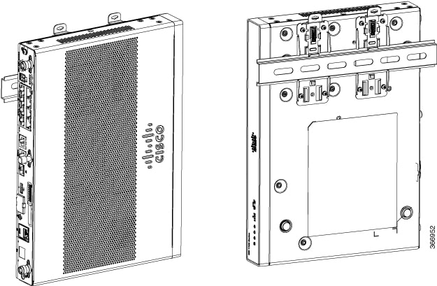
The Cisco 1100 Series ISRs have mounting key-hole slots on the bottom of the chassis for mounting the unit on a wall or other vertical surface, as shown in the figure below.
Note | The unit must not be mounted with the output ports facing downwards. You must mount the unit with the cables going sideways. |
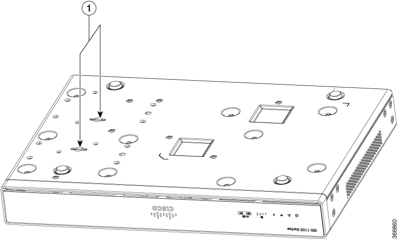
|
1 |
Key-hole slots |
Note | To attach to a wall stud, each bracket requires one number-10 wood screws (round- or pan-head) with number-10 washers, or two number-10 washer-head screws. The screws must be long enough to penetrate at least 1.5 inches (38.1 mm) into the supporting wood or metal wall stud. |
Note | For hollow-wall mounting, each bracket requires two wall anchors with washers. Wall anchors and washers must be size number 10. Route the cables so that they do not put a strain on the connectors or mounting hardware. |
Note | When choosing a location for wall-mounting the router, consider cable limitations and wall structure. |
The figure below shows the orientation for wall mounting of the router.
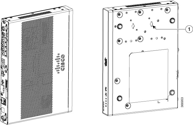
|
1 |
Key-hole slots |
Attaching DIN Rail Brackets
Step 1: Attach the brackets to the router chassis as shown in the figure below, using the PHMS screws and the plastic spacers provided for each bracket.
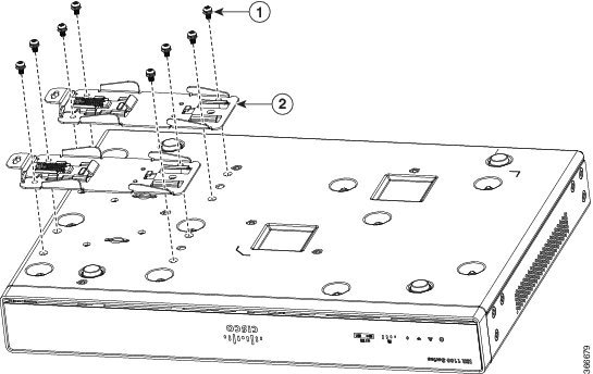
|
1 |
Screws |
|
2 |
DIN Rail Brackets |
Note | Do not over-torque the screws. The recommended torque is 8 to 10 inch-lbf (.9 to 1.1 N-m). |
Note | Your chassis installation must allow unrestricted airflow for chassis cooling. |
Step 2: Attach the router to the wall using the key-hole slots.
The figure below displays the orientation of the DIN rail bracket.
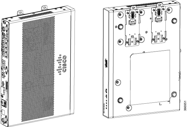
The figure below displays the DIN rail orientation and mount.
After the router is installed, you must connect the chassis to a reliable earth ground. For the chassis ground connection procedures, see the “Chassis Grounding” section.
Mounting the Router in a Rack
-
Attach the brackets to the router chassis (towards the left or right) as shown in figure below. Figure 6. Bracket Installation for Left-Hand-Mounting 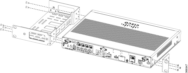
Note
In the similar manner, you can install the bracket on the right-hand for mounting.
-
Use the screws provided with the rack to install the chassis in the rack.
Warning | To prevent bodily injury when mounting or servicing this unit in a rack, you must take special precautions to ensure that the system remains stable. The following guidelines are provided to ensure your safety:
|
Warning | Warning To prevent airflow restriction, allow clearance around the ventilation openings to be at least: 1.75 in. (4.4 cm). Statement 1076 |
After the router is installed, you must connect the chassis to a reliable earth ground. For the chassis ground connection procedures, see the “Chassis Grounding” section.
Setting the Chassis on a Desktop
You can place the router on a desktop, bench top, or shelf.
After the router is installed, you must connect the chassis to a reliable earth ground. For the chassis ground connection procedures, see the Chassis Grounding section.
Chassis Grounding
Warning | This equipment must be grounded. Never defeat the ground conductor or operate the equipment in the absence of a suitably installed ground conductor. Contact the appropriate electrical inspection authority or an electrician if you are uncertain that suitable grounding is available. Statement 1024 |
You must connect the chassis to a reliable earth ground; the ground wire must be installed in accordance with local electrical safety standards.
-
For grounding, use size 14 AWG copper wire and the ground lug (which are not a part of the accessory kit).
-
Use the UNC 6-32 screws, which have a length of about 0.25 inches
Note | Use 14AWG wire for installation. |
To install the ground connection for your router, perform the following steps:
-
Strip one end of the ground wire to the length required for the ground lug or terminal.
-
For the ground lug—approximately 0.75 inch (20 mm)
-
For user-provided ring terminal—as required
-
-
Crimp the ground wire to the ground lug or ring terminal, using a crimp tool of the appropriate size.
-
Attach the ground lug or ring terminal to the chassis as shown in Figure. For a ground lug, one of the screws provided. Tighten the screw to a torque of 8 to 10 in-lb (0.9 to 1.1 N-m).
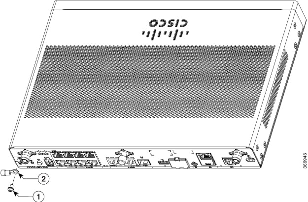
|
1 |
Screw (UNC 6-32) |
|
2 |
Ground Lug |
Connecting to a Console Terminal or Modem
The router has asynchronous serial ports. These ports provide administrative access to the router either locally (with a console terminal or a PC) or remotely (with a modem).To configure the router through the Cisco IOS CLI, you must establish a connection between the router console port and either a terminal or a PC.
Use the following cables and adapters to establish a local or remote connection.
|
Port Type |
Cable |
Section |
|---|---|---|
|
Serial (RJ-45) |
EIA RJ-45 |
Connecting to the Serial Port with Microsoft Windows |
|
Serial (USB) |
Micro USB Type-B to USB Type-A |
- Connecting to the Serial Port with Microsoft Windows
- Connecting to the Console Port with Mac OS X
- Connecting to the Console Port with Linux
Connecting to the Serial Port with Microsoft Windows
Note | Install the USB device driver before establishing a physical connection between the router and the PC using the USB Console cable plugged into the USB serial port, otherwise the connection will fail. See the “Installing the Cisco Microsoft Windows USB Device Driver” section. |
-
Connect the end of the console cable with the RJ-45 connector to the light blue console port on the router.
-
or
Connect a USB 5-pin micro USB Type-B to the USB console port. If you are using the USB serial port for the first time on a Windows-based PC, install the USB driver now according to the instructions in the following sections.
-
“Installing the Cisco Microsoft Windows XP USB Driver” section
-
“Installing the Cisco Microsoft Windows 2000 USB Driver” section
-
“Installing the Cisco Microsoft Windows Vista USB Driver” section
-
"Installing the Cisco Microsoft Windows 8 and Windows 10 USB Driver" section
Note
You cannot use the USB port and the EIA port concurrently. When the USB port is used it takes priority over the RJ-45 EIA port.
-
-
Connect the end of the cable with the DB-9 connector (or USB Type-A) to the terminal or PC. If your terminal or PC has a console port that does not accommodate a DB-9 connector, you must provide an appropriate adapter for that port.
-
To communicate with the router, start a terminal emulator application. This software should be configured with the following parameters:
-
9600 baud
-
8 data bits
-
no parity
-
1 stop bit
-
no flow control
-
Connecting to the Console Port with Mac OS X
This procedure describes how to connect a Mac OS X system USB port to the console using the built in OS X Terminal utility.
Connecting to the Console Port with Linux
This procedure shows how to connect a Linux system USB port to the console using the built in Linux Terminal utility.
Installing the Cisco Microsoft Windows USB Device Driver
A USB device driver must be installed the first time a Microsoft Windows-based PC is connected to the USB serial port on the router.
This section contains the following topics:
- Installing the Cisco Microsoft Windows XP USB Driver
- Installing the Cisco Microsoft Windows 2000 USB Driver
- Installing the Cisco Microsoft Windows Vista USB Driver
- Installing the Cisco Microsoft Windows 8/Windows 10 USB Driver
Installing the Cisco Microsoft Windows XP USB Driver
This procedure shows how to install the Microsoft Windows XP USB driver.
Before you begin, download the appropriate driver for your router model from the Cisco Software Download site, USB Console Software category: http://www.cisco.com/cisco/software/navigator.html
Installing the Cisco Microsoft Windows 2000 USB Driver
This procedure shows how to install the Microsoft Windows 2000 USB driver.
Installing the Cisco Microsoft Windows Vista USB Driver
This procedure shows how to install the Microsoft Windows Vista USB driver.
Installing the Cisco Microsoft Windows 8/Windows 10 USB Driver
This procedure shows how to install the Microsoft Windows 8/Windows 10 USB driver.
| Step 1 | Obtain the Cisco USB console driver file from the Cisco.com web site and unzip it.
| ||
| Step 2 | If using 32-bit Windows 8 or Windows 10, double-click the setup.exe file in the Windows_32 folder. If using 64-bit Windows Vista or Windows 8 or Windows 10, double-click the setup(x64).exe file in the Windows_64 folder. | ||
| Step 3 | The Cisco Virtual Com InstallShield Wizard begins. Click Next. | ||
| Step 4 | The Ready to Install the Program window appears, Click Install.
| ||
| Step 5 | The InstallShield Wizard Completed window appears. Click Finish. | ||
| Step 6 | Connect the USB cable to the PC and router USB console ports. The LED for the USB console port turns green, and within a few moments a series of Found New Hardware Wizard windows appear. Follow the instructions to complete the installation of the driver. | ||
| Step 7 | The USB console is now ready for use. |
Uninstalling the Cisco Microsoft Windows USB Driver
This section provides instructions for how to uninstall the Cisco Microsoft Windows USB device driver.
- Uninstalling the Cisco Microsoft Windows XP and 2000 USB Driver
- Uninstalling the Cisco Microsoft Windows Vista USB Driver
Uninstalling the Cisco Microsoft Windows XP and 2000 USB Driver
This procedure shows you how to uninstall both the Microsoft Windows XP and 2000 USB driver. The driver can be removed using the Windows Add Remove Programs utility or the setup.exe program.
Using the Add Remove Programs utility
Disconnect the router console terminal before uninstalling the driver.
-
Click Start > Control Panel > Add or Remove Programs.
-
Scroll to Cisco Virtual Com and click Remove.
-
When the Program Maintenance window appears, select the Remove radio button. Click Next.
Using the Setup.exe program
Note | Disconnect the router console terminal before uninstalling the driver. |
-
Run the setup.exe for Windows 32-bit or setup(x64).exe for Windows-64bit. Click Next.
-
The InstallShield Wizard for Cisco Virtual Com appears. Click Next.
-
When the Program Maintenance window appears, select the Remove radio button. Click Next.
-
When the Remove the Program window appears, click Remove.
-
When the InstallShield Wizard Completed window appears click Finish.
Uninstalling the Cisco Microsoft Windows Vista USB Driver
This procedure shows you how to uninstall the Microsoft Windows Vista USB driver.
Note | Disconnect the router console terminal before uninstalling the driver. |
| Step 1 | Run the setup.exe for Windows 32-bit or setup(x64).exe for Windows-64bit. Click Next. | ||
| Step 2 | The InstallShield Wizard for Cisco Virtual Com appears. Click Next. | ||
| Step 3 | When the Program Maintenance window appears, select the Remove radio button. Click Next. | ||
| Step 4 | When the Remove the Program window appears, click Remove.
| ||
| Step 5 | When the InstallShield Wizard Completed window appears click Finish. |
Connecting WAN and LAN Interfaces
This section describes how to connect WAN and LAN interface cables. It covers the following topics:
Warning | Do not work on the system or connect or disconnect cables during periods of lightning activity. Statement 1001 |
Warning | Class 1 laser product. Statement 1008 |
Warning | Hazardous network voltages are present in WAN ports regardless of whether power to the unit is OFF or ON. To avoid electric shock, use caution when working near WAN ports. When detaching cables, detach the end away from the unit first. Statement 1026 |
Caution | To comply with the Telcordia GR-1089 NEBS standard for electromagnetic compatibility and safety, connect Gigabit Ethernet ports using RJ-45 connectors for shielded twisted pair cable only to intra-building or unexposed wiring or cable. The intra-building cable must be shielded and the shield must be grounded at both ends. The intra-building port(s) of the equipment or subassembly must not be metallically connected to interfaces that connect to the OSP or its wiring. These interfaces are designed for use as intra-building interfaces only (Type 2 or Type 4 ports as described in GR-1089-CORE, Issue 4) and require isolation from the exposed OSP cabling. The addition of Primary Protectors is not sufficient protection in order to connect these interfaces metallically to OSP wiring. |
Warning | Never install telephone jacks in wet locations unless the jack is specifically designed for wet locations. Statement 1036 |
Warning | Never touch uninsulated telephone wires or terminals unless the telephone line has been disconnected at the network interface. Statement 1037 |
Warning | For connections outside the building where the equipment is installed, the following ports must be connected through an approved network termination unit with integral circuit protection, LAN, PoE. Statement 1044 |
Warning | Avoid using or servicing any equipment that has outdoor connections during an electrical storm. There may be a risk of electric shock from lightning. Statement 1088 |
Ports and Cabling
This chapter summarizes typical WAN and LAN connections for routers. The connections summarized here are also described in detail in the document on Cisco.com: Cisco Modular Access Router Cable Specifications
|
Port or Connection |
Port Type, Color1 |
Connection: |
Cable |
|---|---|---|---|
|
Ethernet |
RJ-45, yellow |
Ethernet hub or Ethernet switch |
Category 5 or higher Ethernet |
|
Cisco serial |
60-pin D-sub, blue |
CSU/DSU and serial network or equipment |
Cisco serial transition cable that matches the signaling protocol (EIA/TIA-232, EIA/TIA-449, V.35, X.21, or EIA-530) and the serial port operating mode (DTE or DCE).2 |
|
Cisco Smart serial |
Cisco Smart compact connector, blue |
CSU/DSU and serial network or equipment |
|
|
Gigabit Ethernet SFP, optical |
LC, color according to optical wavelength |
1000BASE-SX, -LX, -LH, -ZX, -CWDM |
Optical fiber as specified on applicable data sheet |
|
Gigabit Ethernet SFP, copper |
RJ-45 |
1000BASE-T |
Category 5, 5e, 6 UTP |
Connection Procedures and Precautions
-
Connect each WAN and LAN to the appropriate connector on the chassis.
-
Position the cables carefully, so that they do not put strain on the connectors.
-
Organize cables in bundles so that cables do not intertwine.
-
Inspect the cables to make sure that the routing and bend radius is satisfactory. Reposition cables, if necessary.
-
Install cable ties in accordance with site requirements.
For cable pinouts, see Cisco Modular Access Router Cable Specifications .
 Feedback