Configure Optical Modules

This chapter describes how to configure the Optical Amplifier Module and Protection Switching Module (PSM).


Note


When you plan to replace a configured optical module with a different type of optical module, you must clear the configurations of the old module before you install the new module. For example, when replacing a configured EDFA module with a PSM in the same slot, clear the EDFA configurations.

In general, configurations in a card equipped in an NCS 1001 slot include:

  • Card configuration—hw-module parameters configuration related to the slot S where the card is equipped

  • OTS controller configurations

  • Optics controller configurations—only for EDFA cards

The following commands clear the configurations in the previous card.

  1. no hw-module location 0/RP0/CPU0 slot <S>

    Clear the card parameters configuration.

  2. no controller ots Rack/Slot/Instance/Port

    Clear each OTS controller configuration.

  3. no controller optics Rack/Slot/Instance/Port

    (Optional) Clear the controller optics configurations. This must be done only if the card previously equipped in slot S was an EDFA.


Optical Amplifier Module

The optical amplifier module (NCS1K-EDFA) has pre-amplifier and booster amplifier.

The optical amplifier module provides the following functionality.

  • Preamplifier (LINE-RX to COM-TX) - Single preamplifier variant, with switchable gain ranges, according to link loss:

    • Range # 1: 0 to 24 dB gain, Tilt control: 24 to 27 gain, with tilt uncontrolled

    • Range # 2: 20 to 34 dB gain, Tilt control: 34 to 37 dB gain, with tilt uncontrolled

    • 23dBm output power @ COM-TX port

  • Booster amplifier (COM-RX to LINE-TX) - True variable gain booster amplifier

    • Gain range: 1 to 20. 20 to 25 uncontrolled tilt.

    • 23dBm output power @ LINE-TX port

  • ADD/DROP OSC channel supports both 1510nm and 1610nm +/-10nm

  • OCM assesses channel presence and Gain regulation and per channel power monitoring.
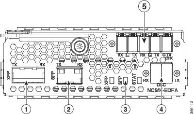
Figure 1. EDFA Front View

EDFA Front View

1

XFP for OSC and additional OTDR feature

2

SFP for OSC (Optical Service Channel)

3

Status LED

4

Service Channel input and output port [OSC - RX, TX]

5

PRE and BST amplifier inputs and output ports

[L (LINE) - RX, TX]

[C (COM) - RX, TX]

[COM - TX CHECK]

The following table describes the mapping of controllers and optical ports for the optical amplifier module.

Controller

Optical Ports

Ots 0/slot/0/0

  • COM-RX (booster input)

  • COM-TX (preamplifier output)

Ots 0/slot/0/1

  • LINE-RX (preamplifier input)

  • LINE-TX (booster output)

Ots 0/slot/0/2

  • OSC-RX

  • OSC-TX

Ots 0/slot/0/3

COM-CHECK

Amplifier Configuration

NCS 1001 supports two methods to control amplifiers.

  • Manual-All the amplifier settings are controlled by the user.

  • Automatic-All the amplifier settings are controlled by the internal amplifier power regulator.

UDC Port Configuration

There are three UDC RJ-45 ports on the faceplate of NCS 1001. Each port is statically associated with a slot (UDC1 to slot 1, UDC2 to slot 2 and UDC3 to slot3). UDC ports are one Gigabit Ethernet ports and the user can transmit any Ethernet traffic into these ports.

UDC traffic flows through the line, added and dropped by the OSC add/drop filters in the optical amplifier module (NCS1K-EDFA). UDC traffic flows through the line tagged. The tagging and untagging operations are performed by NCS 1001, based on the UDC VLAN specified in the configuration, without any limit on the transmitted traffic. The traffic can be tagged, multiple tagged, or untagged. However, 100% utilization cannot be achieved because four bytes of tag are added to each packet.

UDC Application for Remote Management

The following diagrams describe the application of UDC that can be used by EPNM to manage NCS 1000 series at the remote site.

Figure 2. UDC Application for Remote Management - Scenario One
UDC Application for Remote Management
Figure 3. UDC Application for Remote Management - Scenario Two
UDC Application for Remote Management

Configure Amplifier Module

configure

hw-module location 0/RP0/CPU0 slot slot-number ampli

node-type value

grid-mode value

udc-vlan value

commit

end

Example

The following is a sample in which the amplifier module is inserted in slot 3 and udc-vlan is set to 4000.


configure
hw-module location 0/RP0/CPU0 slot 3 ampli
   [
       grid-mode 100GHz
       udc-vlan 4000
   ]

Amplifier Module Configuration Parameters

Table 1. Amplifier Module Configuration Parameters

Parameter

Description

Range/Values

Default

grid-mode

Defines the optical spectrum on the interfaces of the amplifier module.

  • 100GHz-Configures the amplifier with 100GHz grid of channels with 48 channel spacing.

  • 50GHz-Configures the amplifier with 50GHz grid of channels with 96 channel spacing.

  • gridless-Configures the amplifier in the flex spectrum.

50GHz

node-type

Defines the type of the node in which the amplifier is set to work.

TERM, ILA

TERM

udc-vlan

Defines the VLAN associated to the selected slot and its UDC port.

2 to 4080

Protection Switching Module

The protection switching module (NCS1K-PSM) provides the following functionality.

  • In TX section:

    • Splits input optical channels to both working and protection lines.

    • Forces the switch in the remote site by opening one of the two line paths (by putting the related VOA in AVS).

  • In RX section:

    • Selects the signals from working or protection line. Each line is monitored through a PD.

    • Balances the two line losses by changing the VOA attenuation value at the same time of the switch change of state.

Figure 4. PSM Front View

PSM Front View

1

Protected path input and output port [P - RX, TX]

2

Working path input and output port [W - RX, TX]

3

COM input and output port [COM - RX, TX]

4

Status LED

The following table describes the mapping of controllers and optical ports for the protection switching module.

Controller

Optical Ports

Ots 0/slot/0/0

COM-TX

Ots 0/slot/0/1

Working path input and output port [W - RX, TX]

Ots 0/slot/0/2

Protected path input and output port [P - RX, TX]

Configure Protection Switching Module

The following table explains the possible configuration on Protection Switching Module:

PSM Module Configuration Parameters

Table 2. PSM Module Configuration Parameters

Parameter

Description

Range/Values

lockout-from

Excludes the selected port from protection.

Triggers a switch when the active port is specified in the lockout.

For example, configuring a lockout-from working port triggers a switch to protect when working port is the active one.

While lockout-from protected port triggers a switch to working when protected port is the active one.

Working and Protected

path-protection

Enables the PSM path protection.

section-protection

Enables the PSM section protection.

uni-dir

Enables the PSM uni directional (in switches only).

auto-threshold

Enables the PSM auto threshold setting.

Example

The following is an example of configuration of a lockout from working in which the PSM is inserted in slot 2.


conf t
#hw-module location 0/RP0/CPU0 slot 2 psm lockout-from "working"
commit

You can apply manual switching by using the following command:

hw-module slot slot number manual-switch-to working | protected


Note


FPD upgrade on FW_PSMv1 from FW 1.43 and FW 1.44 to FW 1.45 affects the traffic.


(From R6.2.1) Section Protection

Figure 5. Section Protection Topology
Section Protection Topology

See the PSM Module Configuration Parameters section to set the section-protection parameter on both the PSMs. Ensure that the PSM in a section protection topology is inserted in slot 2. Connect the EDFA in slot 1 to the Protected port of the PSM and EDFA in slot 3 to the Working port of the PSM.


Note


To measure the correct switching time while testing the section protection topology, we recommend you to wait for 120 seconds between two subsequent switching events (or between a switching event and the restoration). This waiting period allows the EDFAs to stabilize after the first switching occurrence, thus avoiding the power at the PSM to oscillate around the threshold.


Protection Switching Module with Manual Threshold

The switch can operate in all conditions, if it is set in Autothreshold.

When the path protection is configured with a manual threshold, you must ensure that:

  • During the first installation, the value on the PSM RX-low Threshold should be set as 3 dB below the minimum power for a single channel. The value must ensure that the PSM is able to switch on with a single channel or when the EDFA is in APR (+8 dBm).

  • When the system is up and running with the final number of channels, the PSM RX-low Threshold must be set 3 dB below the target power.

  • After a fiber cut and restore, in order to ensure that the PSM is able to switch on, it is necessary to set the value of PSM RX-low Threshold similar to the value set during the first installation.

The PSM Auto-threshold configuration is highly recommended for a three-way topology.

In a three-way topology, when the path protection is configured with a manual threshold, you must follow the above steps. If you did not configure all the above steps properly, you may encounter the following issues:

  • Switch may not be bidirectional.

  • Double switch on PSM in path protection, when set in three-way configuration.

It is possible to configure parameters such as rx-enable, tx-enable in OTS controllers (1 or 2, i.e. working or protected port) of PSM card.

For more information on OTS controllers, see Configure OTS Controller.