- About this Guide
- Chapter 1, Cisco ONS 15454 (ANSI and ETSI), ONS 15454 M2, and ONS 15454 M6 Shelf Assembly
- Chapter 2, Common Control Cards
- Chapter 3, Optical Service Channel Cards
- Chapter 4, Optical Amplifier Cards
- Chapter 5, Multiplexer and Demultiplexer cards
- Chapter 6, Tunable Dispersion Compensating Units
- Chapter 7, Protection Switching Module
- Chapter 8, Optical Add/Drop Cards
- Chapter 9, Reconfigurable Optical Add/Drop Cards
- Chapter 10, Transponder and Muxponder Cards
- Chapter 11, Node Reference
- Chapter 12, Network Reference
- Chapter 13, Optical Circuit Reference
- Chapter 14, Cisco Transport Controller Operation
- Chapter 15, Security Reference
- Chapter 16, Timing Reference
- Chapter 17, Manage Network Connectivity
- Chapter 18, Alarm Management
- Chapter 19, Performance Monitoring
- Chapter 20, SNMP
- Appendix A, Hardware Specifications
- Appendix B, Administrative and Service States
- Appendix C, Pseudo Command Line Interface Reference
- Appendix D, Fiber and Connector Losses in Raman Link Configuration
- Appendix E, Network Element Defaults
- 9.1 Card Overview
- 9.2 Safety Labels for Class 1M Laser Product Cards
- 9.3 32WSS Card
- 9.4 32WSS-L Card
- 9.5 32DMX Card
- 9.6 32DMX-L Card
- 9.7 40-DMX-C Card
- 9.8 40-DMX-CE Card
- 9.9 40-MUX-C Card
- 9.10 40-WSS-C Card
- 9.11 40-WSS-CE Card
- 9.12 40-WXC-C Card
- 9.13 80-WXC-C Card
- 9.14 Single Module ROADM (SMR-C) Cards
- 9.14.1 SMR-C Card Key Features
- 9.14.2 40-SMR1-C Card
- 9.14.2.1 40-SMR1-C Faceplate Ports
- 9.14.2.2 40-SMR1-C Block Diagram
- 9.14.2.3 40-SMR1-C Power Monitoring
- 9.14.2.4 40-SMR1-C Channel Plan
- 9.14.2.5 40-SMR1-C Card-Level Indicators
- 9.14.2.6 40-SMR1-C Port-Level Indicators
- 9.14.3 40-SMR2-C Card
- 9.14.3.1 40-SMR2-C Faceplate Ports
- 9.14.3.2 40-SMR2-C Block Diagram
- 9.14.3.3 40-SMR2-C Power Monitoring
- 9.14.3.4 40-SMR2-C Channel Plan
- 9.14.3.5 40-SMR2-C Card-Level Indicators
- 9.14.3.6 40-SMR2-C Port-Level Indicators
- 9.15 MMU Card
Reconfigurable Optical Add/Drop Cards
This chapter describes the Cisco ONS 15454 cards deployed in reconfigurable optical add/drop (ROADM) networks. For installation and card turn-up procedures, refer to the Cisco ONS 15454 DWDM Procedure Guide. For card safety and compliance information, refer to the Cisco Optical Transport Products Safety and Compliance Information document.

Note![]() The cards described in this chapter are supported on the Cisco ONS 15454, Cisco ONS 15454 M6, Cisco ONS 15454 M2 platforms, unless noted otherwise.
The cards described in this chapter are supported on the Cisco ONS 15454, Cisco ONS 15454 M6, Cisco ONS 15454 M2 platforms, unless noted otherwise.
Note![]() Unless otherwise specified, “ONS 15454” refers to both ANSI and ETSI shelf assemblies.
Unless otherwise specified, “ONS 15454” refers to both ANSI and ETSI shelf assemblies.
- Card Overview
- Safety Labels for Class 1M Laser Product Cards
- 32WSS Card
- 32WSS-L Card
- 32DMX Card
- 32DMX-L Card
- 40-DMX-C Card
- 40-DMX-CE Card
- 40-MUX-C Card
- 40-WSS-C Card
- 40-WSS-CE Card
- 40-WXC-C Card
- 80-WXC-C Card
- Single Module ROADM (SMR-C) Cards
- MMU Card
Note![]() This chapter contains information about cards that perform mesh topology functions. Multiplexer and demultiplexer cards that do not perform these functions are described in Chapter5, “Multiplexer and Demultiplexer Cards”
This chapter contains information about cards that perform mesh topology functions. Multiplexer and demultiplexer cards that do not perform these functions are described in Chapter5, “Multiplexer and Demultiplexer Cards”
9.1 Card Overview
The ROADM cards include six add drop cards utilized in the C-band (32WSS, 32DMX, 32DMX-C, 40-MUX-C, 40-WXC-C, 80-WXC-C, and MMU), two add drop cards utilized for the L-band (32WSS-L, and 32DMX-L), and two single module ROADM (SMR) cards utilized in the C-band (40-SMR1-C and 40-SMR2-C).
This section provides card summary, compatibility, channel allocation, and safety information.
Note![]() Each card is marked with a symbol that corresponds to a slot (or slots) on the ONS 15454 shelf assembly. The cards are then installed into slots that have the same symbols. For a list of slots and symbols, see the "Card Slot Requirements" section in the Cisco ONS 15454 Hardware Installation Guide.
Each card is marked with a symbol that corresponds to a slot (or slots) on the ONS 15454 shelf assembly. The cards are then installed into slots that have the same symbols. For a list of slots and symbols, see the "Card Slot Requirements" section in the Cisco ONS 15454 Hardware Installation Guide.
9.1.1 Card Summary
Table 9-1 lists and summarizes information about each ROADM card.
|
|
|
|
|---|---|---|
|
|
The 32WSS card has seven sets of ports located on the faceplate. It operates in Slots 1 to 5 and 12 to 16. |
See the “32WSS Card” section |
|
|
The 32WSS-L card has seven sets of ports located on the faceplate. It operates in Slots 1 to 5 and 12 to 16. |
See the “32WSS-L Card” section |
|
|
The 32DMX has five sets of ports located on the faceplate. It operates in Slots 1 to 6 and 12 to 17. |
See the “32DMX Card” section |
|
|
The 32DMX-L has five sets of ports located on the faceplate. It operates in Slots 1 to 6 and 12 to 17. |
See the “32DMX-L Card” section |
|
|
The 40-DMX-C has six sets of ports located on the faceplate. It operates in Slots 1 to 6 and 12 to 17. |
See the “40-DMX-C Card” section |
|
|
The 40-DMX-CE has six sets of ports located on the faceplate. It operates in Slots 1 to 6 and 12 to 17. |
See the “40-DMX-CE Card” section |
|
|
The 40-MUX-C has six sets of ports located on the faceplate. It operates in Slots 1 to 6 and 12 to 17. |
See the “40-MUX-C Card” section. |
|
|
The 40-WSS-C card has eight sets of ports located on the faceplate. It operates in Slots 1 to 5 and 12 to 16. |
See the “40-WSS-C Card” section |
|
|
The 40-WSS-CE card has eight sets of ports located on the faceplate. It operates in Slots 1 to 5 and 12 to 16. |
See the “40-WSS-CE Card” section |
|
|
The 40-WXC-C card has five sets of ports located on the faceplate. It operates in Slots 1 to 5 and 12 to 16. |
See the “40-WXC-C Card” section |
|
|
The 80-WXC-C card has 14 ports located on the faceplate. It operates in Slots 1 to 5 and 12 to 16. |
See the “80-WXC-C Card” section. |
|
|
The 40-SMR1-C card has six sets of ports located on the faceplate. It operates in Slots 1 to 5 and 12 to 16. |
|
|
|
The 40-SMR2-C card has six sets of ports located on the faceplate. It operates in Slots 1 to 5 and 12 to 16. |
|
|
|
The MMU card has six sets of ports located on the faceplate. It operates in Slots 1 to 6 and 12 to 17. |
See the “MMU Card” section |
9.1.2 Card Compatibility
Table 9-2 lists the Cisco Transport Controller (CTC) software compatibility for the ROADM cards.
|
|
|
|
|
|
|
|
|
|
|
|
|
|
|---|---|---|---|---|---|---|---|---|---|---|---|---|
9.1.3 Interface Classes
The input interface cards have been grouped in classes listed in Table 9-3 . The subsequent tables list the optical performance and output power of each interface class.
Table 9-4 lists the optical performance parameters for 40-Gbps cards.
|
|
|
|
||
|---|---|---|---|---|
|
|
|
(if appl.) |
|
(if appl.) |
Maximum BER2 |
||||
OSNR 1 sensitivity |
||||
| Transmitted Power Range3 |
||||
|
3.These values, decreased by patchcord and connector losses, are also the input power values for the OADM cards. |
Table 9-5 , Table 9-6 , and Table 9-7 lists the optical performance parameters for 10-Gbps cards.
|
|
|
|
|
|
|
|||||
|---|---|---|---|---|---|---|---|---|---|---|
|
|
|
|
|
|
|
|
|
|
|
|
Maximum BER5 |
||||||||||
| OSNR 1 sensitivity |
23 dB6 |
|||||||||
23 dB7 |
||||||||||
23 dB8 |
||||||||||
| Transmitted Power Range9 |
||||||||||
|
|
|
|
|
|
||||
|---|---|---|---|---|---|---|---|---|
|
|
|
|
|
|
|
|
|
|
Maximum BER11 |
||||||||
OSNR 1 sensitivity |
||||||||
| Transmitted Power Range12 |
||||||||
|
12.These values, decreased by patchcord and connector losses, are also the input power values for the optical add drop multiplexer (OADM) cards. |
|
|
|
|
|
|
||||
|---|---|---|---|---|---|---|---|---|
|
|
|
|
|
|
|
|
|
|
Maximum BER14 |
||||||||
OSNR 1 sensitivity |
||||||||
| Transmitted Power Range15 |
||||||||
|
15.These values, decreased by patchcord and connector losses, are also the input power values for the optical add drop multiplexer (OADM) cards. |
Table 9-8 and Table 9-9 lists the optical interface performance parameters for 2.5-Gbps cards.
|
|
|
|
|
|||
|---|---|---|---|---|---|---|
|
|
|
|
|
|
|
|
| Transmitted Power Range16 |
||||||
|
16.These values, decreased by patchcord and connector losses, are also the input power values for the OADM cards. |
|
|
|
|
|
|||
|---|---|---|---|---|---|---|
|
|
|
|
|
|
|
|
| Transmitted Power Range17 |
||||||
|
17.These values, decreased by patchcord and connector losses, are also the input power values for the OADM cards. |
9.1.4 Channel Allocation Plans
ONS 15454 DWDM ROADM cards are designed for use with specific channels in the C band and L band. In most cases, the channels for these cards are either numbered (for example, 1 to 32 or 1 to 40) or delimited (odd or even). Client interfaces must comply with these channel assignments to be compatible with the ONS 15454 system.
. The following cards operate in the C-band:
Table 9-10 lists the C-band channel IDs and wavelengths at ITU-T 50-GHz intervals. This is a comprehensive C-band channel table that encompasses present and future card capabilities.
|
|
|
|
|
|
|
|---|---|---|---|---|---|
|
18.Channels on the C-band are 4-skip-1, starting at 1530.33 nm. |
The following add drop cards utilize the L-band DWDM channels:
Table 9-11 lists the L-band channel IDs and wavelengths at ITU-T 50-GHz intervals. This is a comprehensive L-band channel table that encompasses present and future card capabilities.
|
|
|
|
|
|
|
|
|---|---|---|---|---|---|---|
|
19.Channels on the L-band are contiguous, starting at 1577.86 nm. The channels listed in this table begin with 1570.83 nm for backward compatibility with other ONS products. |
9.2 Safety Labels for Class 1M Laser Product Cards
This section explains the significance of the safety labels attached to some of the cards. The card faceplates are clearly labeled with warnings about the laser radiation levels. You must understand all warning labels before working on these cards.
The 40-SMR1-C and 40-SMR2-C cards have Class IM lasers. The labels that appear on these cards are described in the following subsections.
9.2.1 Class 1M Laser Product Statement
Figure 9-1 shows the Class 1M Laser Product statement.
Figure 9-1 Class 1M Laser Product Statement

Class 1M lasers are products that produce either a highly divergent beam or a large diameter beam. Therefore, only a small part of the whole laser beam can enter the eye. However, these laser products can be harmful to the eye if the beam is viewed using magnifying optical instruments.
9.2.2 Hazard Level 1M Label
Figure 9-2 shows the Hazard Level 1M label. The Hazard Level label warns users against exposure to laser radiation by Class 1 limits calculated in accordance with IEC60825-1 Ed.1.2. This label is displayed on the faceplate of the cards.
9.2.3 Laser Source Connector Label
Figure 9-3 shows the Laser Source Connector label. This label indicates that a laser source is present at the optical connector where the label is located.
Figure 9-3 Laser Source Connector Label

9.2.4 FDA Statement Label
The FDA Statement labels are shown in Figure 9-4 and Figure 9-5. These labels show compliance to FDA standards and that the hazard level classification is in accordance with IEC60825-1 Am.2 or Ed.1.2.
Figure 9-4 FDA Statement Label
Figure 9-5 FDA Statement Label
9.2.5 Shock Hazard Label
Figure 9-6 shows the Shock Hazard label. This label alerts you to electrical hazards within a card. A shock hazard exists when you remove adjacent cards during maintenance, or when you touch exposed electrical circuitry on the card itself.

9.3 32WSS Card
Note![]() See the “32WSS Card Specifications” section for hardware specifications.
See the “32WSS Card Specifications” section for hardware specifications.
The two-slot 32-Channel Wavelength Selective Switch (32WSS) card performs channel add/drop processing within the ONS 15454 DWDM node. The 32WSS card can be installed in the following pairs of slots:
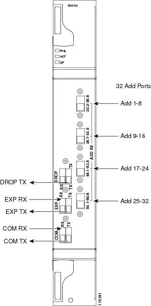
9.3.1 32WSS Faceplate Ports
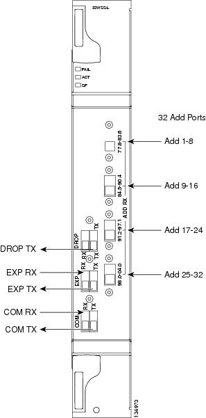
The 32WSS has six types of ports:
- ADD RX ports (1 to 32): These ports are used for adding channels (listed in Table 9-13). Each add channel is associated with an individual switch element that selects whether that channel is added. Each add port has optical power regulation provided by a variable optical attenuator (VOA). The 32WSS has four physical receive connectors that accept multifiber push-on (MPO) cables on its front panel for the client input interfaces.Each MPO cable breaks out into eight separate cables.
- EXP RX port: The EXP RX port receives an optical signal from another 32WSS card in the same network element (NE).
- EXP TX port: The EXP TX port sends an optical signal to the other 32WSS card within the NE.
- COM TX port: The COM TX (line input) port sends an aggregate optical signal to a booster amplifier card (for example, OPT-BST) for transmission outside of the NE.
- COM RX port: The COM RX port receives the optical signal from a preamplifier (such as the OPT-PRE) and sends it to the optical splitter.
- DROP TX port: The DROP TX port sends the split-off optical signal containing drop channels to the 32DMX card, where the channels are further processed and dropped.
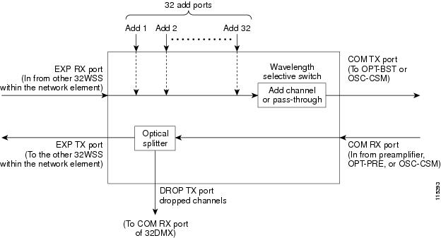
Figure 9-7 shows the 32WSS card front panel and identifies the traffic flow through the ports.
Figure 9-7 32WSS Faceplate and Ports
9.3.2 32WSS Block Diagram
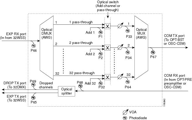
Figure 9-8 provides a high-level functional block diagram of the 32WSS card and Figure 9-9 shows how optical signals are processed on the EXP RX and COM RX ports.
Figure 9-8 32WSS Block Diagram
Aggregate optical signals that enter the EXP RX and COM RX port are processed in two ways: Add channel/pass-through and optical splitter processing. The optical processing stages are shown in Figure 9-9, which provides a detailed optical functional diagram of the 32WSS card.
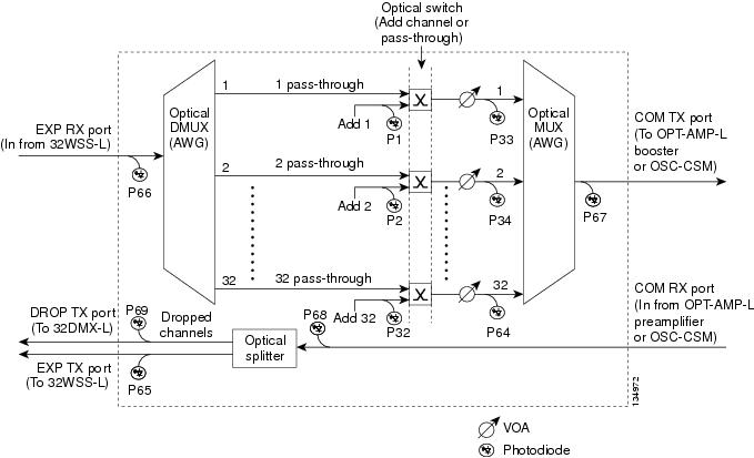
Figure 9-9 32WSS Optical Block Diagram
The EXP RX PORT and COM RX PORT operate as follows:
The incoming optical signal is received at the EXP RX port from the other 32WSS card within the NE. The incoming aggregate optical signal is demultiplexed into 32 individual wavelengths, or channels. Each channel is then individually processed by the optical switch, which performs add/pass-through processing. By using software controls, the switch either selects the optical channel coming in from the demultiplexer (that is, the pass-through channel) or it selects the external ADD channel. If the ADD port channel is selected this channel is transmitted and the optical signal coming from the demultiplexer is blocked.
After the optical switch stage, all of the channels are multiplexed into an aggregate optical signal, which is sent out on the COM TX port. The output is typically connected to an OPT-BST or OPT-BST-E card (in the event a booster amplifier is needed) or to an OSC-CSM card (if no amplification is needed).
The COM RX port receives the incoming optical signal and directs it to the 32WSS card’s optical splitter. The splitter optically diverts channels that are designated to be dropped to the DROP TX port. The DROP TX port is typically connected to the COM RX port of the 32DMX where the drop channels are being dropped. Channels that are not dropped pass-through the optical splitter and flow out of the 32WSS card EXP TX port. Typically, this optical signal is connected to the other 32WSS module within the NE.
The COM TX value can be measured by either a physical or a virtual photodiode of the 15454-32WSS card. If the vendor ID of the 15454-32WSS card is between 1024 (0x400) and 2047 (0x800) the COM TX value is measured by physical photodiode. If the vendor ID of the 15454-32WSS card is greater than 2048 (0x800), the COM TX value is measured by the virtual photodiode. For COM TX values measured by virtual photodiode, check the values at the RX port in the downstream of the COM TX port (COM-RX port on OPT-BST or OSC-CSM card).
9.3.3 32WSS ROADM Functionality
The 32WSS card works in combination with the 32DMX card to implement ROADM functionality. As a ROADM node, the ONS 15454 can be configured to add or drop individual optical channels using CTC, Cisco TransportPlanner, and Cisco Transport Manager (CTM). ROADM functionality using the 32WSS card requires two 32DMX single-slot cards and two 32WSS double-slot cards (totalling six slots needed in the ONS 15454 chassis).
For other cards’ ROADM functionality, see that card’s description in this chapter. For a diagram of a typical ROADM configuration, see the “ROADM Node” section.
Note![]() A terminal site can be configured using only a 32WSS card and a 32DMX card plugged into the east or west side of the shelf.
A terminal site can be configured using only a 32WSS card and a 32DMX card plugged into the east or west side of the shelf.
9.3.4 32WSS Power Monitoring
Physical photodiodes P1 through P69 monitor the power for the 32WSS card. Table 9-12 shows how the returned power level values are calibrated to each port.
|
|
|
|
|---|---|---|
| P33–P6420 |
||
|
20.P33–P64 monitor either ADD or PASSTHROUGH power, depending on the state of the optical switch |
For information on the associated TL1 AIDs for the optical power monitoring points, refer the “CTC Port Numbers and TL1 Aids” section in Cisco ONS SONET TL1 Command Guide, Release 9.2.
9.3.5 32WSS Channel Allocation Plan
The 32WSS Card’s channel labels, frequencies, and wavelengths are listed in Table 9-13.
|
|
|
|
|
|---|---|---|---|
9.3.6 32WSS Card-Level Indicators
Table 9-14 describes the three card-level LED indicators on the 32WSS card.
9.3.7 32WSS Port-Level Indicators
You can find the alarm status of the 32WSS card’s ports using the LCD screen on the ONS 15454 fan-tray assembly. The screen displays the number and severity of alarms on a given port or slot. For the procedure to view these counts, refer to “Manage Alarms” in the Cisco ONS 15454 DWDM Procedure Guide.
9.4 32WSS-L Card
Note![]() See the “32WSS-L Card Specifications” section for hardware specifications.
See the “32WSS-L Card Specifications” section for hardware specifications.
The two-slot 32-Channel Wavelength Selective Switch L-Band (32WSS-L) card performs channel add/drop processing within the ONS 15454 DWDM node. The 32WSS-L card is particularly well suited for use in networks that employ DS fiber or SMF-28 single-mode fiber.The 32WSS-L card can be installed in the following pairs of slots:
9.4.1 32WSS-L Faceplate Ports
The 32WSS-L card faceplate has six types of ports:
- ADD RX ports (1 to 32): These ports are used for adding channels (which are listed in Table 9-16). Each add channel is associated with an individual switch element that selects whether the channel is added. Each add port has optical power regulation provided by a VOA.
- EXP RX port: The EXP RX port receives an optical signal from another 32WSS-L card in the same NE.
- EXP TX port: The EXP TX port sends an optical signal to the other 32WSS-L card within the NE.
- COM TX port: The COM TX port sends an aggregate optical signal to a booster amplifier card (for example, the OPT-BST card) for transmission outside of the NE.
- COM RX port: The COM RX port receives the optical signal from a preamplifier (such as the OPT-PRE) and sends it to the optical splitter.
- DROP TX port: The DROP TX port sends the split-off optical signal with drop channels to the 32DMX-L card, where the channels are further processed and dropped.
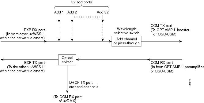
Figure 9-10 shows the 32WSS-L module front panel and identifies the traffic flow through the ports.
Figure 9-10 32WSS-L Faceplate and Ports
9.4.2 32WSS-L Block Diagram
Figure 9-11 provides a high-level functional block diagram of the 32WSS-L card and Figure 9-12 shows how optical signals are processed on the EXP RX and COM RX ports.
Figure 9-11 32WSS-L Block Diagram
Aggregate optical signals that enter the EXP RX and COM RX ports are processed in two ways: add channel/pass-through and optical splitter processing. The optical processing stages are shown in Figure 9-12, which provides a detailed optical functional diagram of the 32WSS-L card.
Figure 9-12 32WSS-L Optical Block Diagram
The EXP RX PORT and COM RX PORT operate as follows:
The incoming optical signal is received at the EXP RX port from the other 32WSS-L card within the NE. The incoming aggregate optical signal is demultiplexed into 32 individual wavelengths, or channels. Each channel is then individually processed by the optical switch, which performs add/pass-through processing. By using software controls, the switch either selects the optical channel coming in from the demultiplexer (that is, the pass-through channel) or it selects the external ADD channel. If the ADD port channel is selected this channel is transmitted and the optical signal coming from the demultiplexer is blocked.
After the optical switch stage, all of the channels are multiplexed into an aggregate optical signal, which is sent out on the COM TX port. The output is typically connected to an OPT-AMP-L or OPT-BST-E card (in the event a booster amplifier is needed) or to an OSC-CSM card (if no amplification is needed).
The COM RX port receives the incoming optical signal and directs it to the 32WSS-L card’s optical splitter. The splitter optically diverts channels that are designated to be dropped to the DROP TX port. The DROP TX port is typically connected to the COM RX port of the 32DMX-L where the drop channels are being dropped. Channels that are not dropped pass-through the optical splitter and flow out of the 32WSS-L card EXP TX port. Typically, this optical signal is connected to the other 32WS-L module within the NE.
9.4.3 32WSS-L ROADM Functionality
The 32WSS-L works in combination with the 32DMX-L to implement L-band (1570 to 1620 nm) functionality. As a ROADM node, the ONS 15454 can be configured to add or drop individual optical channels using CTC, Cisco TransportPlanner, and CTM. ROADM functionality using the 32WSS-L card requires two 32DMX-L single-slot cards and two 32WSS-L double-slot cards (totalling six slots needed in the ONS 15454 chassis).
For other cards’ ROADM functionality, see that card’s description in this chapter. For a diagram of a typical ROADM configuration, see the “ROADM Node” section.
Note![]() A terminal site can be configured using a 32WSS-L card and a 32DMX-L card plugged into the east or west side of the shelf.
A terminal site can be configured using a 32WSS-L card and a 32DMX-L card plugged into the east or west side of the shelf.
9.4.4 32WSS-L Power Monitoring
Physical photodiodes P1 through P69 monitor the power for the 32WSS-L card. Table 9-15 shows the returned power level values calibrated to each port.
|
|
|
|
|---|---|---|
| P33–P6421 |
||
|
21.P33–P64 monitor either ADD or PASSTHROUGH power, depending on the state of the optical switch |
For information on the associated TL1 AIDs for the optical power monitoring points, refer the “CTC Port Numbers and TL1 Aids” section in Cisco ONS SONET TL1 Command Guide, Release 9.2.
9.4.5 32WSS-L Channel Plan
The 32WSS-L card uses 32 banded channels on the ITU-T 100-GHz grid, as shown in Table 9-16 .
|
|
|
|
|
|---|---|---|---|
9.4.6 32WSS-L Card-Level Indicators
Table 9-17 describes the three card-level LED indicators on the 32WSS-L card.
9.5 32DMX Card
Note![]() See the “32DMX Card Specifications” section for hardware specifications.
See the “32DMX Card Specifications” section for hardware specifications.
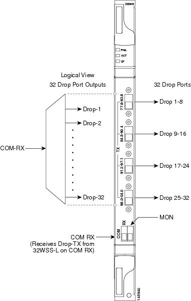
The single-slot 32-Channel Demultiplexer (32DMX) card is an optical demultiplexer. The card receives an aggregate optical signal on its COM RX port and demultiplexes it into to (32) ITU-T 100-GHz-spaced channels. The 32DMX card can be installed in Slots 1 to 6 and in Slots 12 to 17.
9.5.1 32DMX Faceplate Ports
The 32DMX card has two types of ports:
- COM RX port: COM RX is the input port for the aggregate optical signal being demultiplexed. This port is supported by a VOA for optical power regulation and a photodiode for optical power monitoring.
- DROP TX ports (1 to 32): On its output, the 32DMX provides 32 drop ports (listed in Table 9-19) that are typically used for dropping channels within the ROADM node. These ports are connected using four 8-fiber MPO ribbon connectors. The incoming optical signal to the demultiplexer comes into the COM RX port. This input port is connected using a single LC duplex optical connector.Each drop port has a photodiode for optical power monitoring. Unlike the two-slot 32DMX-O demultiplexer, the drop ports on the 32DMX do not have a VOA per channel for optical power regulation. For a description of the 32DMX-O card, see the “32DMX-O Card” section.
Figure 9-13 shows the 32DMX card front panel and the basic traffic flow through the ports.
Figure 9-13 32DMX Faceplate and Ports
9.5.2 32DMX Block Diagram
A block diagram of the 32DMX card is shown in Figure 9-14.
Figure 9-14 32DMX Block Diagram
Figure 9-15 shows the 32DMX optical module functional block diagram.
Figure 9-15 32DMX Optical Module Functional Block Diagram
9.5.3 32DMX ROADM Functionality
The 32DMX card works in combination with the 32WSS card to implement ROADM functionality. As a ROADM node, the ONS 15454 can be configured to add or drop individual optical channels using CTC, Cisco TransportPlanner, and CTM. ROADM functionality using the 32DMX card requires two 32DMX single-slot cards and two 32WSS double-slot cards (for six slots total in the ONS 15454 chassis).
For information about the ROADM functionality for other cards, see that card’s description in this chapter. For a diagram of a typical ROADM configuration, see the “ROADM Node” section.
Note![]() A terminal site can be configured using only a 32WSS card and a 32DMX card plugged into the east or west side of the shelf.
A terminal site can be configured using only a 32WSS card and a 32DMX card plugged into the east or west side of the shelf.
9.5.4 32DMX Power Monitoring
Physical photodiodes P1 through P33 monitor the power for the 32DMX card. The returned power level values are calibrated to the ports as shown in Table 9-18 .
|
|
|
|
|---|---|---|
For information on the associated TL1 AIDs for the optical power monitoring points, refer the “CTC Port Numbers and TL1 Aids” section in Cisco ONS SONET TL1 Command Guide, Release 9.2.
9.5.5 32DMX Channel Allocation Plan
The 32DMX card’s channel labels, frequencies, and wavelengths are listed in Table 9-19.
|
|
|
|
|
|---|---|---|---|
9.5.6 32DMX Card-Level Indicators
Table 9-20 describes the three card-level LED indicators on the 32DMX card.
9.5.7 32DMX Port-Level Indicators
You can find the alarm status of the 32DMX card’s ports using the LCD screen on the ONS 15454 fan-tray assembly. The screen displays the number and severity of alarms on a given port or slot. For the procedure to view these counts, refer to “Manage Alarms” in the Cisco ONS 15454 DWDM Procedure Guide.
9.6 32DMX-L Card
Note![]() See the “32DMX-L Card Specifications” section for hardware specifications.
See the “32DMX-L Card Specifications” section for hardware specifications.
The single-slot 32-Channel Demultiplexer L-Band card (32DMX-L) is an L-band optical demultiplexer. The card receives an aggregate optical signal on its COM RX port and demultiplexes it into to (32) 100-GHz-spaced channels. The 32DMX-L card is particularly well suited for use in networks that employ DS fiber or SMF-28 single-mode fiber. The 32DMX-L card can be installed in Slots 1 to 6 and in Slots 12 to 17.
9.6.1 32DMX-L Faceplate Ports
The 32DMX-L card has two types of ports:
- COM RX port: COM RX is the input port for the aggregate optical signal being demultiplexed. This port is supported by both a VOA for optical power regulation and a photodiode for optical power monitoring.
- DROP TX ports (1 to 32): On its output, the 32DMX-L card provides 32 drop ports (listed in Table 9-25) that are typically used for dropping channels within the ROADM node. These ports are connected using four 8-fiber MPO ribbon connectors. Each drop port has a photodiode for optical power monitoring. Unlike the two-slot 32DMX-O demultiplexer, the drop ports on the 32DMX-L do not have a VOA per channel for optical power regulation. For a description of the 32DMX-O card, see the “32DMX-O Card” section.
Figure 9-16 shows the 32DMX-L card front panel and the basic traffic flow through the ports.
Figure 9-16 32DMX-L Faceplate and Ports
9.6.2 32DMX-L Block Diagram
Figure 9-17 shows a block diagram of the 32DMX-L card.
Figure 9-17 32DMX-L Block Diagram
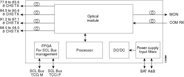
Figure 9-18 shows the 32DMX-L optical module functional block diagram.
Figure 9-18 32DMX-L Optical Module Functional Block Diagram
9.6.3 32DMX-L ROADM Functionality
The 32DMX-L card works in combination with the 32WSS-L card to implement ROADM functionality. AS a ROADM node, the ONS 15454 can be configured to add or drop individual optical channels using CTC, Cisco TransportPlanner, and CTM. ROADM functionality using the 32DMX-L card requires two 32DMX-L single-slot cards and two 32WSS-L double-slot cards (for a total of six slots in the ONS 15454 chassis).
For information about ROADM functionality for other cards, see that card’s description in this chapter. For a diagram of a typical ROADM configuration, see the “ROADM Node” section.
Note![]() A terminal site can be configured using only a 32WSS-L card and a 32DMX-L card plugged into the east or west side of the shelf.
A terminal site can be configured using only a 32WSS-L card and a 32DMX-L card plugged into the east or west side of the shelf.
9.6.4 32DMX-L Power Monitoring
Physical photodiodes P1 through P33 monitor the power for the 32DMX-L card. The returned power level values are calibrated to the ports as shown in Table 9-21 .
|
|
|
|
|---|---|---|
For information on the associated TL1 AIDs for the optical power monitoring points, refer the “CTC Port Numbers and TL1 Aids” section in Cisco ONS SONET TL1 Command Guide, Release 9.2.
9.6.5 32DMX-L Channel Plan
The 32DMX-L card uses 32 banded channels on the ITU-T 100-GHz grid, as shown in Table 9-22 .
|
|
|
|
|
|---|---|---|---|
9.6.6 32DMX-L Card-Level Indicators
Table 9-23 describes the three card-level LED indicators on the 32DMX-L card.
9.6.7 32DMX-L Port-Level Indicators
You can find the alarm status of the 32DMX-L card’s ports using the LCD screen on the ONS 15454 fan-tray assembly. The screen displays the number and severity of alarms on a given port or slot. For the procedure to view these counts, refer to “Manage Alarms” in the Cisco ONS 15454 DWDM Procedure Guide.
9.7 40-DMX-C Card
(Cisco ONS 15454 and ONS 15454 M6 only)
Note![]() See the “40-DMX-C Card Specifications” section for hardware specifications.
See the “40-DMX-C Card Specifications” section for hardware specifications.
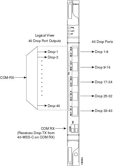
The single-slot 40-Channel Demultiplexer C-band (40-DMX-C) card demultiplexes 40 100-GHz-spaced channels identified in the channel plan (Table 9-25), and sends them to dedicated output ports. The overall optical power can be adjusted using a single VOA that is common to all channels. The 40-DMX-C card is unidirectional, optically passive, and can be installed in Slots 1 to 6 and 12 to 17.
9.7.1 40-DMX-C Faceplate Ports
The 40-DMX-C has two types of ports:
- COM RX port: COM RX is the line input port for the aggregate optical signal being demultiplexed. This port is supported by a VOA for optical power regulation and a photodiode for per channel optical power monitoring.
Note![]() By default, the VOA is set to its maximum attenuation for safety purposes (for example, electrical power failure). A manual VOA setting is also available.
By default, the VOA is set to its maximum attenuation for safety purposes (for example, electrical power failure). A manual VOA setting is also available.
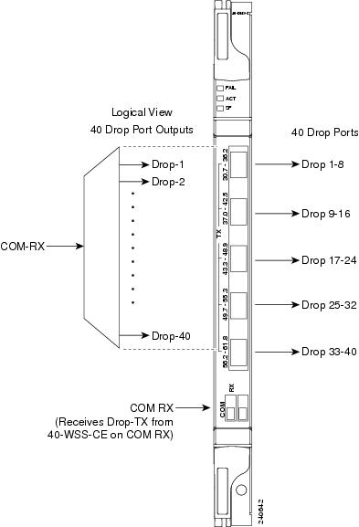
- DROP TX ports (1 to 40): On its output, the 40-DMX-C card provides 40 drop ports that are typically used for dropping channels within the ROADM node. These ports are connected using five physical connectors on the front panel that accept MPO client input cables. (MPO cables break out into eight separate cables.) The 40-DMX-C card also has one LC-PC-II optical connector for the main input.
Figure 9-19 shows the 40-DMX-C card faceplate.
Figure 9-19 40-DMX-C Faceplate
9.7.2 40-DMX-C Block Diagram
Figure 9-20 shows a block diagram of the 40-DMX-C card.
Figure 9-20 40-DMX-C Block Diagram

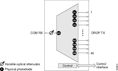
Figure 9-21 shows the 40-DMX-C optical module functional block diagram.
Figure 9-21 40-DMX-C Optical Module Functional Block Diagram
9.7.3 40-DMX-C ROADM Functionality
The 40-DMX-C card works in combination with the 40-WSS-C card to implement ROADM functionality. As a ROADM node, the ONS 15454 can be configured at the optical channel level using CTC, Cisco TransportPlanner, and CTM. ROADM functionality using the 40-DMX-C card requires two single-slot 40-DMX-C cards and two 40-WSS-C double-slot cards (for a total of six slots in the ONS 15454 chassis).
For other cards’ ROADM functionality, see that card’s description in this chapter. For a diagram of a typical ROADM configuration, see the “ROADM Node” section.
9.7.4 40-DMX-C Power Monitoring
Physical photodiodes P1 through P40 monitor the power at the outputs of the 40-DMX-C card. P41 monitors the total multiplexed power at the input, calibrated to the COM-RX port. Table 9-24 shows the returned power level values calibrated to each port.
|
|
|
|
|---|---|---|
For information on the associated TL1 AIDs for the optical power monitoring points, refer the “CTC Port Numbers and TL1 Aids” section in Cisco ONS SONET TL1 Command Guide, Release 9.2.
9.7.5 40-DMX-C Channel Plan
Table 9-25 shows the 40 ITU-T 100-GHz-spaced, C-band channels (wavelengths) that are demultiplexed by the 40-DMX-C card.
|
|
|
|
|
|---|---|---|---|
9.7.6 40-DMX-C Card-Level Indicators
The 40-DMX-C card has three card-level LED indicators, described in Table 9-26 .
9.7.7 40-DMX-C Port-Level Indicators
You can find the alarm status of the 40-DMX-C card ports using the LCD screen on the ONS 15454 fan-tray assembly. The screen displays the number and severity of alarms on a given port or slot. For the procedure to view these counts, refer to “Manage Alarms” in the Cisco ONS 15454 DWDM Procedure Guide.
9.8 40-DMX-CE Card
(Cisco ONS 15454 and ONS 15454 M6 only)
Note![]() See the “40-DMX-CE Card Specifications” section for hardware specifications.
See the “40-DMX-CE Card Specifications” section for hardware specifications.
The single-slot 40-Channel Demultiplexer C-band, even channels (40-DMX-CE) card demultiplexes 40 100-GHz-spaced even-numbered channels identified in the channel plan (Table 9-28), and sends them to dedicated output ports. The overall optical power can be adjusted using a single VOA that is common to all channels. The 40-DMX-CE card is unidirectional, optically passive, and can be installed in Slots 1 to 6 and 12 to 17.
9.8.1 40-DMX-CE Card Faceplate Ports
The 40-DMX-CE card has two types of ports:
- COM RX port: COM RX is the line input port for the aggregate optical signal being demultiplexed. This port is supported by a VOA for optical power regulation and a photodiode for per channel optical power monitoring.
Note![]() By default, the VOA is set to its maximum attenuation for safety purposes (for example, electrical power failure). A manual VOA setting is also available.
By default, the VOA is set to its maximum attenuation for safety purposes (for example, electrical power failure). A manual VOA setting is also available.
- DROP TX ports (1 to 40): On its output, the 40-DMX-CE card provides 40 drop ports that are typically used for dropping channels within the ROADM node. These ports are connected using five physical connectors on the front panel that accept MPO client input cables. (MPO cables break out into eight separate cables.) The 40-DMX-CE card also has one LC-PC-II optical connector for the main input.
Figure 9-22 shows the 40-DMX-CE card faceplate.
Figure 9-22 40-DMX-CE Card Faceplate
9.8.2 40-DMX-CE Card Block Diagram
Figure 9-23 shows a block diagram of the 40-DMX-CE card.
Figure 9-23 40-DMX-CE Card Block Diagram
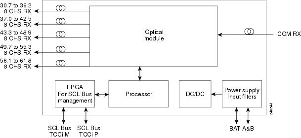
Figure 9-24 shows the 40-DMX-CE card optical module functional block diagram.
Figure 9-24 40-DMX-CE Card Optical Module Functional Block Diagram
9.8.3 40-DMX-CE Card ROADM Functionality
The 40-DMX-CE card works in combination with the 40-WSS-CE card to implement ROADM functionality. As a ROADM node, the ONS 15454 can be configured at the optical channel level using CTC, Cisco TransportPlanner, and CTM. ROADM functionality using the 40-DMX-CE card requires two single-slot 40-DMX-CE cards and two 40-WSS-CE double-slot cards (for a total of six slots in the ONS 15454 chassis).
For the ROADM functionality of other cards, see the description of that card in this chapter. For a diagram of a typical ROADM configuration, see the “ROADM Node” section.
9.8.4 40-DMX-CE Card Power Monitoring
Physical photodiodes P1 through P40 monitor the power at the outputs of the 40-DMX-CE card. P41 monitors the total multiplexed power at the input, calibrated to the COM-RX port. Table 9-27 shows the returned power level values calibrated to each port.
|
|
|
|
|---|---|---|
For information on the associated TL1 AIDs for the optical power monitoring points, refer the “CTC Port Numbers and TL1 Aids” section in Cisco ONS SONET TL1 Command Guide, Release 9.2.
9.8.5 40-DMX-CE Card Channel Plan
Table 9-28 shows the 40 ITU-T 100-GHz-spaced, C-band channels (wavelengths) that are demultiplexed by the 40-DMX-CE card.
|
|
|
|
|
|---|---|---|---|
9.8.6 40-DMX-CE Card-Level Indicators
The 40-DMX-CE card has three card-level LED indicators, described in Table 9-29 .
9.8.7 40-DMX-CE Card Port-Level Indicators
You can find the alarm status of the 40-DMX-CE card ports using the LCD screen on the ONS 15454 fan-tray assembly. The screen displays the number and severity of alarms on a given port or slot. For the procedure to view these counts, refer to the “Manage Alarms” chapter in the Cisco ONS 15454 DWDM Procedure Guide.
9.9 40-MUX-C Card
(Cisco ONS 15454 and ONS 15454 M6 only)
Note![]() See the “40-MUX-C Card Specifications” section for hardware specifications.
See the “40-MUX-C Card Specifications” section for hardware specifications.
The single-slot 40-Channel Multiplexer C-band (40-MUX-C) card multiplexes forty ITU-T 100-GHz-spaced channels identified in the channel plan in Table 9-25. The 40-MUX-C card can be installed in Slots 1 to 6 and 12 to 17. The 40-MUX-C card is typically used in hub nodes.
9.9.1 40-MUX-C Card Faceplate Ports
The 40-MUX-C card has two types of ports:
- COM TX port: COM TX is the line output port for the aggregate optical signal being multiplexed. This port is supported by both a VOA for optical power regulation and a photodiode for per channel optical power monitoring.
Note![]() By default, the VOA is set to its maximum attenuation for safety purposes (for example, electrical power failure). A manual VOA setting is also available.
By default, the VOA is set to its maximum attenuation for safety purposes (for example, electrical power failure). A manual VOA setting is also available.
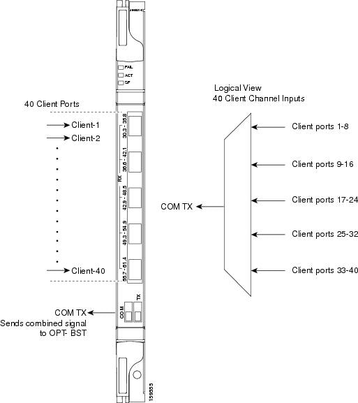
- DROP RX ports (1 to 40): The 40-MUX-C card provides 40 input optical channels. These ports are connected using five physical receive connectors on the card’s front panel that accept MPO cables for the client input interfaces. MPO cables break out into eight separate cables. The 40-DMX-C card also has one LC-PC-II optical connector for the main output. For the wavelength range, see Table 9-25.
Figure 9-25 shows the 40-MUX-C card faceplate.
Figure 9-25 40-MUX-C Card Faceplate
9.9.2 40-MUX-C Card Block Diagram
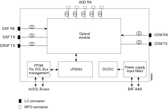
Figure 9-26 shows a block diagram of the 40-MUX-C card.
Figure 9-26 40-MUX-C Card Block Diagram
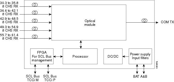
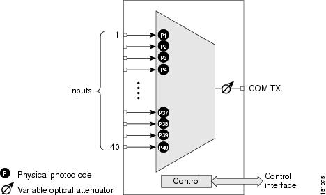
Figure 9-27 shows the 40-MUX-C optical module functional block diagram.
Figure 9-27 40-MUX-C Optical Module Functional Block Diagram
9.9.3 40-MUX-C Card Power Monitoring
Physical photodiodes P1 through P40 monitor the power of the individual input ports to the 40-MUX-C card. P41 monitors the total multiplexed output power, calibrated to the COM-TX port. Table 9-30 shows the returned power level values calibrated to each port.
|
|
|
|
|---|---|---|
For information on the associated TL1 AIDs for the optical power monitoring points, refer the “CTC Port Numbers and TL1 Aids” section in Cisco ONS SONET TL1 Command Guide, Release 9.2.
9.9.4 40-MUX-C Card Channel Plan
Table 9-31 shows the 40 ITU-T 100-GHz-spaced, C-band channels (wavelengths) that are multiplexed by the 40-MUX-C card.
|
|
|
|
|
|---|---|---|---|
9.9.5 40-MUX-C Card-Level Indicators
The 40-MUX-C card has three card-level LED indicators, described in Table 9-32 .
9.9.6 40-MUX-C Port-Level Indicators
You can find the alarm status of the 40-MUX-C card ports using the LCD screen on the ONS 15454 fan-tray assembly. The screen displays the number and severity of alarms on a given port or slot. For the procedure to view these counts, refer to “Manage Alarms” in the Cisco ONS 15454 DWDM Procedure Guide.
9.10 40-WSS-C Card
(Cisco ONS 15454 and ONS 15454 M6 only)
Note![]() See the “40-WSS-C Card Specifications” section for hardware specifications.
See the “40-WSS-C Card Specifications” section for hardware specifications.
The double-slot 40-channel Wavelength Selective Switch C-Band (40-WSS-C) card switches 40 ITU-T 100-GHz-spaced channels identified in the channel plan (Table 9-25) and sends them to dedicated output ports. The 40-WSS-C card is bidirectional and optically passive. The card can be installed in Slots 1 to 6 and 12 to 17
The 40-WSS-C features include:
- Receipt of an aggregate DWDM signal into 40 output optical channels from the Line receive port (EXP RX) in one direction and from the COM-RX port in the other direction.
- Per-channel optical power monitoring using photodiodes.
- Signal splitting in a 70%-to-30% ratio, sent to the 40-DMX-C for dropping signals, then to the other 40-WSS-C card.
- Aggregate DWDM signal monitoring and control through a variable optical attenuator (VOA). In the case of electrical power failure, the VOA is set to its maximum attenuation for safety purposes. A manual VOA setting is also available.
Within the 40-WSS-C card, the first AWG opens the spectrum and each wavelength is directed to one of the ports of a 1x2 optical switch. The same wavelength can be passed through or stopped. If the pass-through wavelength is stopped, a new channel can be added at the ADD port. The card’s second AWG multiplexes all of the wavelengths, and the aggregate signal is output through the COM-TX port.
9.10.1 40-WSS-C Faceplate Ports
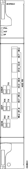
The 40-WSS-C has eight types of ports:
- ADD RX ports (1 to 40): These ports are used for adding channels. Each add channel is associated with an individual switch element that selects whether an individual channel is added. Each add port has optical power regulation provided by a VOA. The five connectors on the card faceplate accept MPO cables for the client input interfaces. MPO cables break out into eight separate cables. The 40-WSS-C card also has one LC-PC-II optical connector for the main input.
- COM RX: The COM RX port receives the optical signal from a preamplifier (such as the OPT-PRE) and sends it to the optical splitter.
- COM TX: The COM TX port sends an aggregate optical signal to a booster amplifier card (for example, the OPT-BST card) for transmission outside of the NE.
- EXP RX port: The EXP RX port receives an optical signal from another 40-WSS-C card in the same NE.
- EXP TX: The EXP TX port sends an optical signal to the other 40-WSS-C card within the NE.
- DROP TX port: The DROP TX port sends the split off optical signal that contains drop channels to the 40-DMX-C card, where the channels are further processed and dropped.
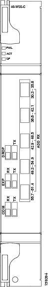
Figure 9-28 shows the 40-WSS-C card faceplate.
Figure 9-28 40-WSS-C Faceplate
9.10.2 40-WSS-C Block Diagram
Figure 9-29 shows a block diagram of the 40-WSS-C card.
Figure 9-29 40-WSS-C Block Diagram
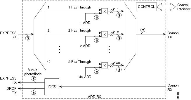
Figure 9-30 shows the 40-WSS-C optical module functional block diagram.
Figure 9-30 40-WSS-C Optical Module Functional Block Diagram
9.10.3 40-WSS-C ROADM Functionality
The 40-WSS-C card works in combination with the 40-DMX-C card to implement ROADM functionality. As a ROADM node, the ONS 15454 can be configured at the optical channel level using CTC, Cisco TransportPlanner, and CTM. ROADM functionality using the 40-WSS-C card requires two 40-WSS-C double-slot cards and two 40-DMX-C single-slot cards (for a total of six slots in the ONS 15454 chassis).
For information about ROADM functionality for other cards, see that card’s description in this chapter. For a diagram of a typical ROADM configuration, see the “ROADM Node” section.
9.10.4 40-WSS-C Power Monitoring
The 40-WSS-C has physical diodes that monitor power at various locations on the card. Table 9-33 lists the physical diode descriptions.
|
|
|
|
|---|---|---|
PDi322 |
Add i RX ports (that is, channel input Add i RX power), up to 40 ports and therefore 40 PDs 1 |
|
PDi4 1 |
COM TX port (that is, per channel output COM TX power) up to 40 channels and therefore 40 PDs |
|
|
|
For information on the associated TL1 AIDs for the optical power monitoring points, refer the “CTC Port Numbers and TL1 Aids” section in Cisco ONS SONET TL1 Command Guide, Release 9.2.
Additionally, the 40-WSS-C has two virtual diodes. Virtual diodes are monitor points for each physical photodiode; they are identified with a physical diode relative to the way that the physical diode is identified with one of the two interlink (ILK) ports. Table 9-34 lists the virtual diodes.
|
|
|
|
|---|---|---|
9.10.5 40-WSS-C Channel Plan
Table 9-35 shows the 40 ITU-T 100-GHz-spaced, C-band channels (wavelengths) that are switched by the 40-WSS-C card.
|
|
|
|
|
|---|---|---|---|
9.10.6 40-WSS-C Card-Level Indicators
The 40-WSS-C card has three card-level LED indicators, described in Table 9-36 .
9.10.7 40-WSS-C Port-Level Indicators
You can find the alarm status of the 40-WSS-C card ports using the LCD screen on the ONS 15454 fan-tray assembly. The screen displays the number and severity of alarms on a given port or slot. For the procedure to view these counts, refer to the “Manage Alarms” chapter in the Cisco ONS 15454 DWDM Procedure Guide.
9.11 40-WSS-CE Card
(Cisco ONS 15454 and ONS 15454 M6 only)
Note![]() See the “40-WSS-CE Card Specifications” section for hardware specifications.
See the “40-WSS-CE Card Specifications” section for hardware specifications.
The double-slot 40-channel Wavelength Selective Switch Even-Channel C-Band (40-WSS-CE) card switches 40 ITU-T 100-GHz-spaced channels identified in the channel plan (Table 9-39) and sends them to dedicated output ports. The 40-WSS-CE card is bidirectional and optically passive. The card can be installed in Slots 1 to 6 and 12 to 17.
The 40-WSS-CE features include:
- Receipt of an aggregate DWDM signal into 40 output optical channels from the Line receive port (EXP RX) in one direction and from the COM-RX port in the other direction.
- Per-channel optical power monitoring using photodiodes.
- Signal splitting in a 70-to-30 percent ratio, sent to the 40-DMX-CE card for dropping signals, then to the other 40-WSS-CE card.
- Aggregate DWDM signal monitoring and control through a VOA. In the case of electrical power failure, the VOA is set to its maximum attenuation for safety purposes. A manual VOA setting is also available.
Within the 40-WSS-CE card, the first AWG opens the spectrum and each wavelength is directed to one of the ports of a 1x2 optical switch. The same wavelength can be passed through or stopped. If the pass-through wavelength is stopped, a new channel can be added at the ADD port. The card’s second AWG multiplexes all of the wavelengths, and the aggregate signal is output through the COM-TX port.
9.11.1 40-WSS-CE Faceplate Ports
The 40-WSS-CE card has eight types of ports:
- ADD RX ports (1 to 40): These ports are used for adding channels. Each add channel is associated with an individual switch element that selects whether an individual channel is added. Each add port has optical power regulation provided by a VOA. The five connectors on the card faceplate accept MPO cables for the client input interfaces. MPO cables break out into eight separate cables. The 40-WSS-CE card also has one LC-PC-II optical connector for the main input.
- COM RX: The COM RX port receives the optical signal from a preamplifier (such as the OPT-PRE) and sends it to the optical splitter.
- COM TX: The COM TX port sends an aggregate optical signal to a booster amplifier card (for example, the OPT-BST card) for transmission outside of the NE.
- EXP RX port: The EXP RX port receives an optical signal from another 40-WSS-CE card in the same NE.
- EXP TX: The EXP TX port sends an optical signal to the other 40-WSS-CE card within the NE.
- DROP TX port: The DROP TX port sends the split off optical signal that contains drop channels to the 40-DMX-C card, where the channels are further processed and dropped.
Figure 9-31 shows the 40-WSS-CE card faceplate.
Figure 9-31 40-WSS-CE Faceplate
9.11.2 40-WSS-CE Card Block Diagram
Figure 9-32 shows a block diagram of the 40-WSS-CE card.
Figure 9-32 40-WSS-CE Block Diagram
Figure 9-33 shows the 40-WSS-CE optical module functional block diagram.
Figure 9-33 40-WSS-CE Card Optical Module Functional Block Diagram
9.11.3 40-WSS-CE Card ROADM Functionality
The 40-WSS-CE card works in combination with the 40-DMX-CE card to implement ROADM functionality. As a ROADM node, the ONS 15454 can be configured at the optical channel level using CTC, Cisco TransportPlanner, and CTM. ROADM functionality using the 40-WSS-CE card requires two 40-WSS-CE double-slot cards and two 40-DMX-CE single-slot cards (for a total of six slots in the ONS 15454 chassis).
For information about ROADM functionality for another cards, see the description of that card in this chapter. For a diagram of a typical ROADM configuration, see the “ROADM Node” section.
9.11.4 40-WSS-CE Card Power Monitoring
The 40-WSS-CE card has physical diodes that monitor power at various locations on the card. Table 9-37 lists the physical diode descriptions.
|
|
|
|
|---|---|---|
PDi323 |
Add i RX ports (that is, channel input Add i RX power), up to 40 ports and therefore 40 PDs 1 |
|
PDi4 1 |
COM TX port (that is, per channel output COM TX power) up to 40 channels and therefore 40 PDs |
|
|
|
For information on the associated TL1 AIDs for the optical power monitoring points, refer the “CTC Port Numbers and TL1 Aids” section in Cisco ONS SONET TL1 Command Guide, Release 9.2.
Additionally, the 40-WSS-CE card has two virtual diodes. Virtual diodes are monitor points for each physical photodiode; they are identified with a physical diode relative to the way that the physical diode is identified with one of the two interlink (ILK) ports. Table 9-38 lists the virtual diodes.
|
|
|
|
|---|---|---|
9.11.5 40-WSS-CE Card Channel Plan
Table 9-39 shows the 40 ITU-T 100-GHz-spaced, C-band channels (wavelengths) that are switched by the 40-WSS-CE card.
|
|
|
|
|
|---|---|---|---|
9.11.6 40-WSS-CE Card-Level Indicators
The 40-WSS-CE card has three card-level LED indicators, described in Table 9-40 .
9.11.7 40-WSS-CE Card Port-Level Indicators
You can find the alarm status of the 40-WSS-CE card ports using the LCD screen on the ONS 15454 fan-tray assembly. The screen displays the number and severity of alarms on a given port or slot. For the procedure to view these counts, refer to the “Manage Alarms” chapter in the Cisco ONS 15454 DWDM Procedure Guide.
9.12 40-WXC-C Card
(Cisco ONS 15454 and ONS 15454 M6 only)
Note![]() See the “40-WXC-C Card Specifications” section or hardware specifications.
See the “40-WXC-C Card Specifications” section or hardware specifications.
The double-slot 40-channel Wavelength Cross-Connect C-band (40-WXC-C) card selectively sends any wavelength combination coming from nine input ports to a common output port. The device can manage up to 41 channels spaced at 100GHz on each port according to the channel grid in Table 9-10. Each channel can be selected from any input. The card is optically passive and provides bidirectional capability. It can be installed in Slots 1 to 6 and 12 to 17.
.The 40-WXC-C card provides the following features:
- Demultiplexing, selection, and multiplexing of DWDM aggregate signal from input ports to common output port.
- Aggregate DWDM signal monitoring and control through a VOA.
- VOAs are deployed in every channel path in order to regulate the channel’s optical power. In the case of an electrical power failure, VOAs are set to their maximum attenuation value, or to a fixed and configurable one. The VOA can also be set manually.
- Per-channel optical power monitoring using photodiodes.
The 40-WXC-C card acts as a selector element with the following characteristics:
- It is able to select a wavelength from one input port and pass the wavelength through to the common out port. Simultaneously, the card can block the same wavelength coming from the other eight input ports.
- It is able to stop wavelengths from all nine inputs.
- It is able to monitor optical power and control path attenuation using per channel VOA independently of the wavelength input-to-out port connection.
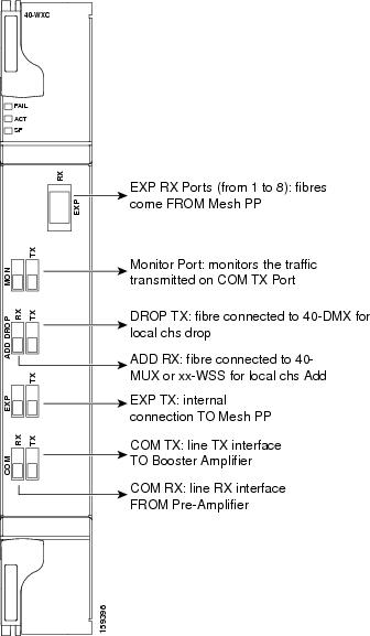
9.12.1 40-WXC-C Faceplate Ports
The 40-WXC-C card has six types of ports:
- COM RX: The COM RX port receives the optical signal from a preamplifier (such as the OPT-PRE) and sends it to the optical splitter.
- COM TX: The COM TX port sends an aggregate optical signal to a booster amplifier card (for example, the OPT-BST card) for transmission outside of the NE.
- EXP TX: The EXP TX port sends an optical signal to the other 40-WXC-C card within the NE.
- MON TX: The optical service channel (OSC) monitor.
- ADD/DROP RX: The 40-WXC-C card provides 40 input optical channels. For the wavelength range, see Table 9-43.
- ADD/DROP TX: The DROP TX port sends the split off optical signal that contains drop channels to the 40-WXC-C card, where the channels are further processed and dropped.
Figure 9-34 shows the 40-WXC-C card faceplate.
Figure 9-34 40-WXC-C Faceplate
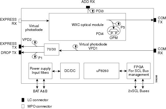
9.12.2 40-WXC-C Block Diagram
Figure 9-35 shows the 40-WXC-C optical module functional block diagram.
Figure 9-35 40-WXC-C Optical Module Functional Block Diagram
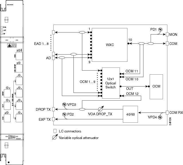
9.12.3 40-WXC-C Power Monitoring
The 40-WXC-C has 83 physical diodes (P1 through P40) that monitor power at the outputs of the card. Table 9-41 describes the physical diodes.
|
|
|
|
|---|---|---|
PDi324 |
Add i RX ports (that is, channel input Add i RX power), up to 40 ports and therefore 40 PDs 1 |
|
PDi4 1 |
COM TX port (that is, per channel output COM TX power) up to 40 channels and therefore 40 PDs |
|
|
|
For information on the associated TL1 AIDs for the optical power monitoring points, refer the “CTC Port Numbers and TL1 Aids” section in Cisco ONS SONET TL1 Command Guide, Release 9.2.
Additionally, the 40-WXC-C has two virtual diodes. Virtual diodes are monitor points for each physical photodiode; they are identified with a physical diode relative to the way that the physical diode is identified with one of the two interlink (ILK) ports. Table 9-42 lists the virtual diodes.
|
|
|
|
|---|---|---|
The usage of WXC and mesh PP power readings to troubleshoot a LOS-P in WXC COM TX port in Side A is described in the following example. The example is explained assuming a single wavelength 1558.17 in the setup that comes from Side H to Side A. If there is more than one wavelength, then there is a risk of dropping traffic when pulling common fibers. The example is explained below:
When the wavelength from side H is 1558.17, you can check the power reading at WXC EXP TX port of the WXC card and verify the consistency with side H pre output power and WXC COMRX-EXPTX port loss. You can also check with a power meter connected to the 8th fiber (since it is from side H) of an MPO-FC (or LC) cable connected to the TAP-TX port of the MESH-PP. This value should be consistent with the previous reading, less than the insertion loss of the installed PP-MESH. If it is consistent, the issue is with the MPO between side A WXC and PP-MESH. If it is not consistent, the issue is with the PP-MESH or the LC-LC from side H. With only the PP-MESH already tested during installation, the only issue can be with the patch cord b.
You can check if the 1558.17 wavelength from side H is unequalized (that is, if the channel is not aligned with the linear fit of the power values of the other channels) by keeping the DMX COM-RX port of side H in maintenance, and checking both the signal and ASE levels of CHAN-TX ports of the DMX card. If the channel is equalized (that is, if the channel is aligned with the linear fit of the power values of the other channels), then the issue is in the WXC side A that cannot properly regulate the VOA for such channel. If the channel is unequalized, then the issue is on a remote node.
Note![]() With an OSA or a spare 40 DMX, you can see the light coming from all the sides from TAP-TX of the PP-MESH.
With an OSA or a spare 40 DMX, you can see the light coming from all the sides from TAP-TX of the PP-MESH.
9.12.4 40-WXC-C Channel Plan
Table 9-43 shows the 40 ITU-T 100-GHz-spaced, C-band channels (wavelengths) that are cross connected by the 40-WXC-C card.
|
|
|
|
|
|---|---|---|---|
Ch. 025 |
|||
|
|
9.12.5 40-WXC-C Card-Level Indicators
The 40-WXC-C card has three card-level LED indicators described in Table 9-44 .
9.12.6 40-WXC-C Port-Level Indicators
You can find the alarm status of the 40-WXC-C card ports using the LCD screen on the ONS 15454 fan-tray assembly. The screen displays the number and severity of alarms on a given port or slot. For the procedure to view these counts, refer to “Manage Alarms” in the Cisco ONS 15454 DWDM Procedure Guide.
9.13 80-WXC-C Card
(Cisco ONS 15454 and ONS 15454 M6 only)
Note![]() See the “80-WXC-C Card Specifications” section or hardware specifications.
See the “80-WXC-C Card Specifications” section or hardware specifications.
The double-slot 80-channel Wavelength Cross-Connect C-band (80-WXC-C) card manages up to 80 ITU-T 100-GHz-spaced channels identified in the channel plan (Table 9-10) and sends them to dedicated output ports. Each channel can be selected from any input port to any output port. The card is optically passive, and provides bidirectional capability. It can be installed in Slots 1 to 5 and 12 to 16 the ONS 15454 chassis and Slots 2 to 6 in the ONS 15454 M6 chassis.
The 80-WXC-C card provides the following functionalities:
- When used in the multiplexer or bidirectional mode, the 80-WXC-C card allows selection of a single wavelength or any combination of wavelengths from any of the nine input ports to the common output port.
- When used in the bidirectional mode, the output wavelength from the COM-RX port is split to manage the express and drop wavelengths.
- When used in the demultiplexer mode, the 80-WXC-C card, allows selection of a single wavelength or a combination of wavelengths from the common input port to any of the nine output ports.
- Automatic VOA shutdown (AVS) blocking state on each wavelength and port.
- Per-channel (closed loop) power regulation on the output port based on OCM block feedback.
- Per-channel (open loop) attenuation regulation on the output port which is not based on the OCM feedback.
The OCM unit provides per-channel optical power monitoring on the following ports:
- COM port in output direction
- COM port in input direction
- DROP-TX port in output direction
- Eight Express/Add/Drop (EAD) ports and one Add/Drop (AD) port in both input and output directions
9.13.1 80-WXC-C Faceplate and Optical Module Functional Block Diagram
The 80-WXC-C card has 14 types of ports:
- MON: The MON port monitors power on the COM T/R port.
- COM RX: The COM RX port receives the optical signal from a preamplifier (such as the OPT-PRE) and sends it to the optical splitter.
- DROP TX: In the bidirectional mode, the DROP TX port sends the optical signal to the demultiplexer.
- EXP TX: The EXP TX port sends the split off optical signal that contains pass-through channels to the other side of the NE.
- COM T/R: The COM port is bidirectional. It functions as a COM TX port in the multiplexer mode and as a COM RX port in the demultiplexer mode.
- AD T/R: The AD port functions as ADD RX port in bidirectional and multiplexer modes and as a DROP port in the demultiplexer mode.
- EAD T/R i (where i = 1 to 8): The EAD ports function as EXP ports in the bidirectional mode, as ADD ports in the multiplexer mode, and as DROP ports in the demultiplexer mode.
Figure 9-36 shows the 80-WXC-C card faceplate and the optical module functional block diagram.
Figure 9-36 80-WXC-C Faceplate and the Optical Module Functional Block Diagram
The different units of the 80-WXC-C card are:
- 40/60 splitter with VOA on drop path—The preamplifier output signal from the preamplifier is split in a 40%-to-60% ratio; 40% is sent on the drop path (DROP-TX port) and 60% is sent on the pass-through path (EXP-TX port). The VOA equipped on the drop path is used to match the power range of the receiver photodiode without the need for bulk attenuation. If a channel is expected to be dropped in the 80-WXC-C card, the pass-through channel is stopped after the EXP-TX port either by a 40-WSS-C or a 40-WXC-C card.
- 50 Ghz 10 port WXC—The WXC block is optically passive and has bidirectional capability. The WXC block can selectively send any wavelength combination coming from the eight input EAD ports and one AD port to a common (COM) output port, when used as a multiplexer, whereas it can selectively send any wavelength combination coming from its common (COM) input port to any of the eight output EAD ports and one AD port, when used as a demultiplexer. The WXC block can manage (on each port) up to 80 channels according to the channel grid reported in Table 9-47. Each channel can be selected from any input and routed to any output.
- 50 Ghz Optical Channel Monitor (OCM)—The OCM provides per channel power monitoring on the COM T/R, DROP-TX, AD, and EAD i ( i =1 to 8) ports. The power value for each wavelength is refreshed after a variable timer depending on the port and card activity.
9.13.2 80-WXC-C Power Monitoring
The 80-WXC-C has two physical photodiodes and an OCM unit that monitors power at the different ports of the card. Table 9-45 describes the physical photodiodes.
|
|
|
|
|---|---|---|
For information on the associated TL1 AIDs for the optical power monitoring points, see the “CTC Port Numbers and TL1 Aids” section in the Cisco ONS SONET TL1 Command Guide, Release 9.2.
Additionally, the 80-WXC-C has two virtual photodiodes. Table 9-46 lists the virtual photodiodes.
|
|
|
|
|---|---|---|
9.13.3 80-WXC-C Channel Plan
Table 9-47 shows the 80 ITU-T 50-GHz-spaced, C-band channels (wavelengths) that are cross connected by the 80-WXC-C card.
|
|
|
|
|
|---|---|---|---|
Ch. 026 |
|||
|
|
9.13.4 80-WXC-C Card-Level Indicators
The 80-WXC-C card has three card-level LED indicators described in Table 9-48 .
9.13.5 80-WXC-C Port-Level Indicators
You can find the alarm status of the 80-WXC-C card ports using the LCD screen or unit. The LCD screen is on the ONS 15454 and ONS 15454 M2 fan-tray assembly and is a separate unit in ONS 15454 M6. The screen displays the number and severity of alarms on a given port or slot. For the procedure to view these counts, see the “Manage Alarms” section in the Cisco ONS 15454 DWDM Procedure Guide.
9.14 Single Module ROADM (SMR-C) Cards
Note![]() See the “40-SMR1-C Card Specifications” section and “40-SMR2-C Card Specifications” section, or hardware specifications.
See the “40-SMR1-C Card Specifications” section and “40-SMR2-C Card Specifications” section, or hardware specifications.
Note![]() For 40-SMR1-C and 40-SMR2-C safety label information, see the “Safety Labels for Class 1M Laser Product Cards” section.
For 40-SMR1-C and 40-SMR2-C safety label information, see the “Safety Labels for Class 1M Laser Product Cards” section.
The single-slot 40-channel single module ROADM (SMR-C) cards integrate the following functional blocks onto a single line card:
- Optical preamplifier
- Optical booster amplifier
- Optical service channel (OSC) filter
- 2x1 wavelength cross-connect (WXC) or a 4x1 WXC
- Optical channel monitor (OCM)
The SMR-C cards are available in two versions:
The SMR-C cards can manage up to 40 channels spaced at 100GHz on each port according to the channel grid in Table 9-10 . The cards can be installed in Slots 1 to 6 and 12 to 17.
9.14.1 SMR-C Card Key Features
The optical amplifier units in the SMR-C cards provide the following features:
- Embedded gain flattening filter
- Mid-stage access for dispersion compensation unit (only applicable for preamplifier erbium-doped fiber amplifier [EDFA])
- Fixed output power mode
- Fixed gain mode
- Nondistorting low-frequency transfer function
- Amplified spontaneous emissions (ASE) compensation in fixed gain and fixed output power mode
- Fast transient suppression
- Programmable tilt (only applicable for preamplifier EDFA)
- Full monitoring and alarm handling capability
- Optical safety support through signal loss detection and alarm at any input port, fast power down control, and reduced maximum output power in safe power mode.
- EDFA section calculates the signal power, by taking into account the expected ASE power contribution to the total output power. The signal output power or the signal gain can be used as feedback signals for the EDFA pump power control loop.
The 1x2 WXC unit (40-SMR1-C card) provides the following features:
- Selection of individual wavelength of the aggregated 100GHz signal from either the EXP-RX or ADD-RX ports
- Automatic VOA shutdown (AVS) blocking state on each wavelength and port
- Per-channel power regulation based on external OCM unit
- Open loop path attenuation control for each wavelength and port
The 1x4 WXC unit (40-SMR2-C card) provides the following features:
- Selection of individual wavelength of the aggregated 100GHz signal from either the EXP i -RX (where i = 1, 2, 3) or ADD-RX ports
- Automatic VOA shutdown (AVS) blocking state on each wavelength and port
- Per-channel power regulation based on external OCM unit
- Open loop path attenuation control for each wavelength and port
The OCM unit provides per channel optical power monitoring at EXP-RX, ADD-RX, DROP-TX, and LINE-TX ports.
9.14.2 40-SMR1-C Card
The 40-SMR1-C card includes a 100Ghz 1x2 WXC unit with integrated preamplifier unit (single EDFA).
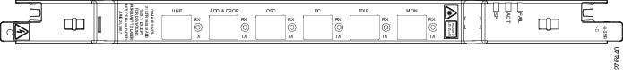
9.14.2.1 40-SMR1-C Faceplate Ports
The 40-SMR1-C card has the following types of ports:
- MON RX: The MON RX port monitors power on the EXP-TX output port.
- MON TX: The MON TX port monitors power on the LINE-TX output port.
- DC RX: The DC RX port receives the optical signal from the dispersion compensating unit (DCU) and sends it to the second stage preamplifier input.
- DC TX: The DC TX port sends the optical signal from the first stage preamplifier output to the DCU.
- OSC RX: The OSC RX port is the OSC add input port.
- OSC TX: The OSC TX port is the OSC drop output port.
- ADD/DROP RX: The ADD RX port receives the optical signal from the multiplexer section of the NE and sends it to the 1x2 WXC unit.
- ADD/DROP TX: The DROP TX port sends the split off optical signal to the demultiplexer section of the NE.
- LINE RX: The LINE RX port is the input signal port.
- LINE TX: The LINE TX port is the output signal port.
- EXP RX: The EXP RX port receives the optical signal from the other side of the NE and sends it to the 1x2 WXC unit.
- EXP TX: The EXP TX port sends the split off optical signal that contains pass-through channels to the other side of the NE.
Figure 9-37 shows the 40-SMR1-C card faceplate.
Figure 9-37 40-SMR1-C Faceplate
9.14.2.2 40-SMR1-C Block Diagram
Figure 9-38 shows a block diagram of the 40-SMR1-C card.
Figure 9-38 40-SMR1-C Block Diagram
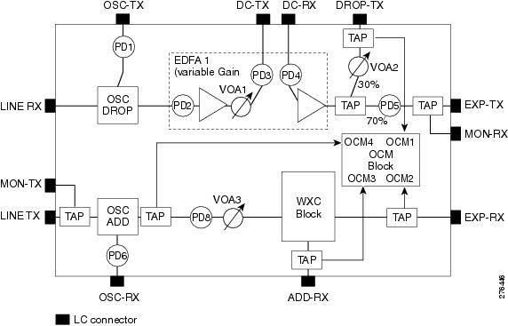
The different units of the 40-SMR1-C card are:
- OSC filter—The OSC filter allows to add an OSC channel to the C-band in the transmission path and to drop an OSC channel on the receiving path. The OSCM card that is connected to the OSC-TX and OSC-RX ports generates the OSC channel.
- Double-stage variable gain EDFA preamplifier—The double-stage preamplifier allows the insertion of a DCU between the DC-TX and DC-RX ports to compensate for chromatic dispersion. It is also equipped with built-in variable optical attenuator (VOA) and gain flattening filter (GFF) that provides tilt compensation and enables the use of this device over an extended range of span losses (5 dB to 35 dB).
- 70/30 splitter and VOA—The output signal from the preamplifier is split in a 70%-to-30% ratio, 70% is sent on the pass-through path (EXP-TX port) and 30% is sent on the drop path (DROP-TX port). The VOA equipped on the drop path is used to match the power range of the receiver photo diode without the need for bulk attenuation. If a channel is expected to be dropped in the 40-SMR1-C card, the pass-through channel is stopped after the EXP-TX port either by a 40-WSS-C, 40-SMR1-C, or 40-SMR2-C card.
- 1x2 WXC—The 1x2 WXC aggregates on its output port a 100-GHz-spaced optical channel received from either its ADD-RX or EXP-RX port. In addition to the switching function, the 1x2 WXC allows to set a different per channel power for each of the managed wavelengths and also monitor the optical power.
- OCM—The OCM provides per channel power monitoring on the DROP-RX, EXP-RX, ADD-RX, and LINE-TX ports. The power value for each wavelength is refreshed after a variable timer depending on the port and card activity.
9.14.2.3 40-SMR1-C Power Monitoring
The 40-SMR1-C card has seven physical diodes (PD1 through PD6 and PD8) and an OCM unit that monitors power at the input and output ports of the card (see Table 9-49 ).
|
|
|
|
|---|---|---|
9.14.2.4 40-SMR1-C Channel Plan
Table 9-50 shows the 40 ITU-T 100-GHz-spaced, C-band channels (wavelengths) supported by the 40-SMR1-C card.
|
|
|
|
|
|---|---|---|---|
9.14.2.5 40-SMR1-C Card-Level Indicators
The 40-SMR1-C card has three card-level LED indicators described in Table 9-51 .
9.14.2.6 40-SMR1-C Port-Level Indicators
You can find the alarm status of the 40-SMR1-C card ports using the LCD screen on the ONS 15454 fan-tray assembly. The screen displays the number and severity of alarms on a given port or slot. For the procedure to view these counts, refer to “Manage Alarms” in the Cisco ONS 15454 DWDM Procedure Guide.
9.14.3 40-SMR2-C Card
The 40-SMR2-C card includes a 100Ghz 1x4 WXC unit with integrated preamplifier and booster amplifier units (double EDFA).
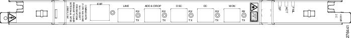
9.14.3.1 40-SMR2-C Faceplate Ports
The 40-SMR2-C card has the following types of ports:
- MON RX: The MON RX port monitors power on the EXP-TX output port.
- MON TX: The MON TX port monitors power on the LINE-TX output port.
- DC RX: The DC RX port receives the optical signal from the dispersion compensating unit (DCU) and sends it to the second stage preamplifier input.
- DC TX: The DC TX port sends the optical signal from the first stage preamplifier output to the DCU.
- OSC RX: The OSC RX port is the OSC add input port.
- OSC TX: The OSC TX port is the OSC drop output port.
- ADD/DROP RX: The ADD RX port receives the optical signal from the multiplexer section of the NE and sends it to the 1x4 WXC unit.
- ADD/DROP TX: The DROP TX port sends the split off optical signal to the demultiplexer section of the NE.
- LINE RX: The LINE RX port is the input signal port.
- LINE TX: The LINE TX port is the output signal port.
- EXP TX: The EXP TX port sends the split off optical signal that contains pass-through channels to the other side of the NE.
- EXP i -RX (where i = 1, 2, 3): The EXP i -RX port receives the optical signal from the other side of the NE and sends it to the 1x4 WXC unit.
Figure 9-37 shows the 40-SMR2-C card faceplate.
Figure 9-39 40-SMR2-C Faceplate
9.14.3.2 40-SMR2-C Block Diagram
Figure 9-38 shows a block diagram of the 40-SMR2-C card.
Figure 9-40 40-SMR2-C Block Diagram
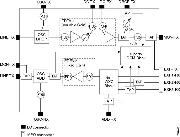
The different units of the 40-SMR2-C card are:
- OSC filter—The OSC filter allows to add an OSC channel to the C-band in the transmission path and to drop an OSC channel on the receiving path. The OSCM card that is connected to the OSC-TX and OSC-RX ports generates the OSC channel.
- Double-stage variable gain EDFA preamplifier—The double-stage preamplifier allows the insertion of a DCU between the DC-TX and DC-RX ports to compensate for chromatic dispersion. It is also equipped with built-in variable optical attenuator (VOA) and gain flattening filter (GFF) that provides tilt compensation and enables the use of this device over an extended range of span losses (5 dB to 35 dB).
- 70/30 splitter and VOA—The output signal from the preamplifier is split in a 70%-to-30% ratio, 70% is sent on the pass-through path (EXP-TX port) and 30% is sent on the drop path (DROP-TX port). The VOA equipped on the drop path is used to match the power range of the receiver photo diode without the need for bulk attenuation. If a channel is expected to be dropped in the 40-SMR2-C card, the pass-through channel is stopped after the EXP-TX port by a 40-WSS-C, 40-SMR1-C, or 40-SMR2-C card.
- 1x4 WXC—The 1x4 WXC aggregates on its output port a 100-GHz-spaced optical channel received from either its ADD-RX or EXP i -RX (where i = 1, 2, 3) port. In addition to the switching function, the 1x4 WXC allows to set a different per channel power for each of the managed wavelengths and also monitor the optical power.
- Single-stage fixed gain EDFA booster amplifier—The booster amplifier amplifies the output signal from the 1x4 WXC unit before transmitting it into the fiber. Since it is a fixed gain (17 dB) amplifier, it does not allow gain tilt control.
- OCM—The OCM provides per channel power monitoring on the DROP-RX, EXP i -RX (where i = 1, 2, 3), ADD-RX, and LINE-TX ports. The power value for each wavelength is refreshed after a variable timer depending on the port and card activity.
9.14.3.3 40-SMR2-C Power Monitoring
The 40-SMR2-C card has eight physical diodes (PD1 through PD8) and an OCM unit that monitors power at the input and output ports of the card (see Table 9-52 ).
|
|
|
|
|---|---|---|
9.14.3.4 40-SMR2-C Channel Plan
Table 9-53 shows the 40 ITU-T 100-GHz-spaced, C-band channels (wavelengths) supported by the 40-SMR2-C card.
|
|
|
|
|
|---|---|---|---|
9.14.3.5 40-SMR2-C Card-Level Indicators
The 40-SMR2-C card has three card-level LED indicators described in Table 9-54 .
9.14.3.6 40-SMR2-C Port-Level Indicators
You can find the alarm status of the 40-SMR2-C card ports using the LCD screen on the ONS 15454 fan-tray assembly. The screen displays the number and severity of alarms on a given port or slot. For the procedure to view these counts, refer to “Manage Alarms” in the Cisco ONS 15454 DWDM Procedure Guide.
9.15 MMU Card
The single-slot Mesh Multi-Ring Upgrade Module (MMU) card supports multiring and mesh upgrades for ROADM nodes in both the C-band and the L-band. Mesh/multiring upgrade is the capability to optically bypass a given wavelength from one section of the network or ring to another one without requiring 3R regeneration. In each node, you need to install one east MMU and one west MMU. The card can be installed in Slots 1 through 6 and 12 through 17.
9.15.1 MMU Faceplate Ports
The MMU has six types of ports:
- EXP RX port: The EXP RX port receives the optical signal from the ROADM section available on the NE.
- EXP TX port: The EXP TX port sends the optical signal to the ROADM section available on the NE.
- EXP-A RX port: The EXP-A RX port receives the optical signal from the ROADM section available on other NEs or rings.
- EXP-A TX port: The EXP-A TX port sends the optical signal to the ROADM section available on other NEs or rings.
- COM TX port: The COM TX port sends the optical signal to the fiber stage section.
- COM RX port: The COM RX port receives the optical signal from the fiber stage section.
Figure 9-41 shows the MMU card faceplate.
Figure 9-41 MMU Faceplate and Ports
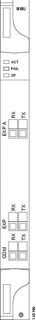
9.15.2 MMU Block Diagram
Figure 9-42 provides a high-level functional block diagram of the MMU card.
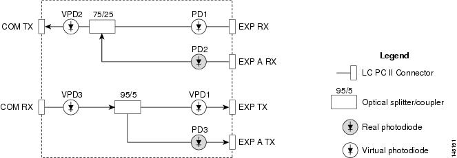
9.15.3 MMU Power Monitoring
Physical photodiodes P1 through P3 monitor the power for the MMU card. The returned power level values are calibrated to the ports as shown in Table 9-55 . VP1 to VP3 are virtual photodiodes that have been created by adding (by software computation) the relevant path insertion losses of the optical splitters (stored in the module) to the real photodiode (P1 to P3) measurement.
|
|
|
|
|---|---|---|
For information on the associated TL1 AIDs for the optical power monitoring points, refer the “CTC Port Numbers and TL1 Aids” section in Cisco ONS SONET TL1 Command Guide, Release 9.2.
9.15.4 MMU Card-Level Indicators
Table 9-56 describes the three card-level LED indicators on the MMU card.
9.15.5 MMU Port-Level Indicators
You can find the alarm status of the MMU card’s ports using the LCD screen on the ONS 15454 fan-tray assembly. The screen displays the number and severity of alarms on a given port or slot. For the procedure to view these counts, refer to “Manage Alarms” in the Cisco ONS 15454 DWDM Procedure Guide.
 Feedback